2 layers
Power driver
MakerMylo/Embroiderino
Forked from an old gitlab repo to hold on to forever.
24 parts1GPL-3.0
 devfabiosilva/TeslaSMPS7
DIY: High Voltage Range Switching Mode Power Supply for Embedded and Solar systems
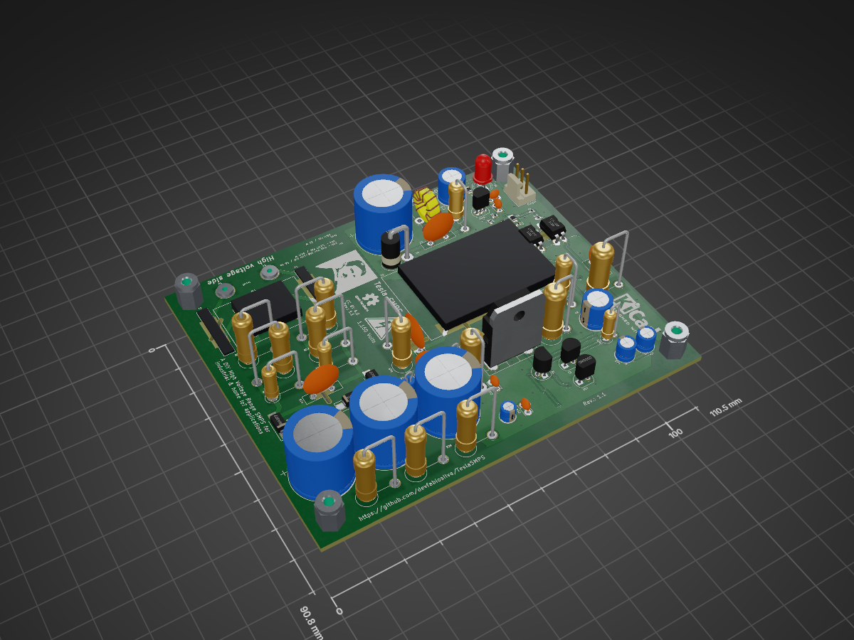
TeslaSMPS is an open-source printed circuit board by devfabiosilva, from the devfabiosilva/TeslaSMPS repository on GitHub, published under the Unlicense licence. It is a 2-layer board of 110.5 × 90.8 mm with 112 parts on 53 nets, routed with 532 tracks and 46 vias.
It is built around the LTV-817, FR103 and FR107, with the 2SK1317-E and UF5404 among its other parts. Its parts include 37 resistors, 22 diodes, 19 capacitors, 3 connectors and 2 ICs. It belongs with the power and home automation and IoT boards of this library.


DIY: High Voltage Range Switching Mode Power Supply for Embedded / Solar and industrial systems
Sponsored by PCB Way. See details here
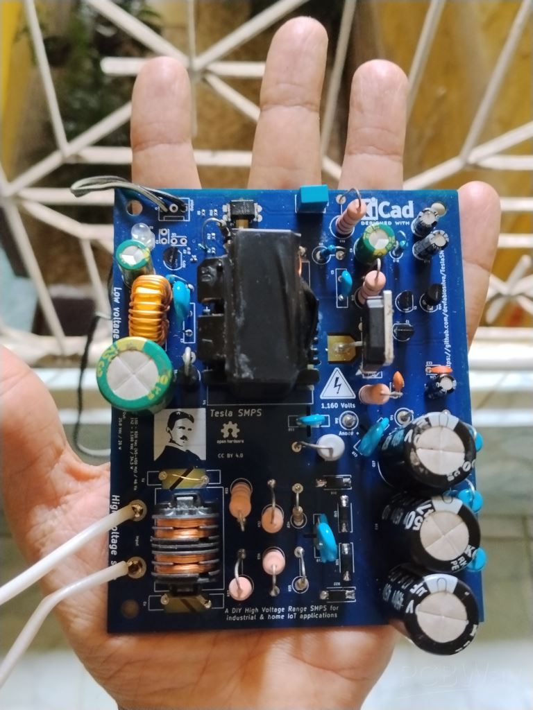
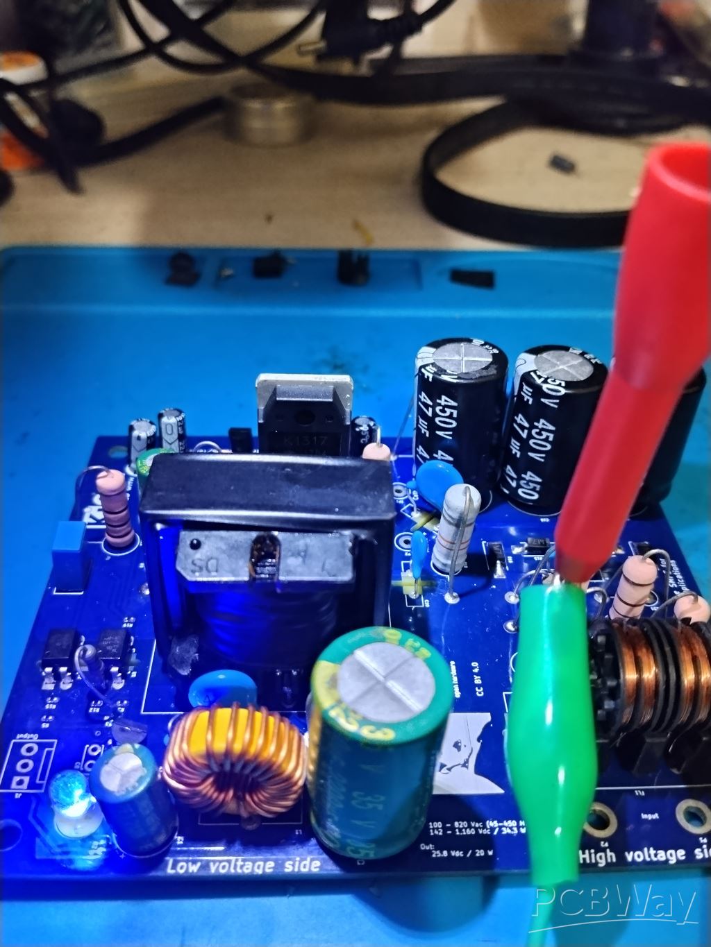
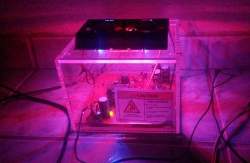
This is a DIY WVR-SMPS (Wide Voltage Range Switching Mode Power Supply) or simply Tesla SMPS is a wide range and high voltage input for low power embedded systems. This device allows input voltage as low as 100 VAC and as high as 820 VAC in wide frequency range (45 − 450 Hz) or even in DC voltage as low as 142 VDC and as high as 1,160 VDC using only 3 transistors
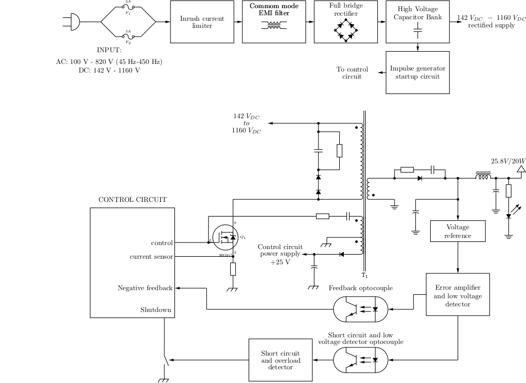
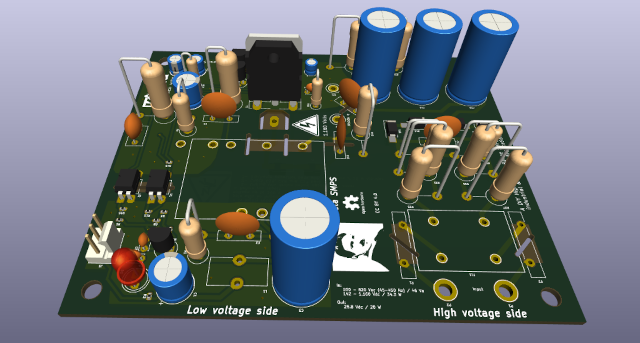
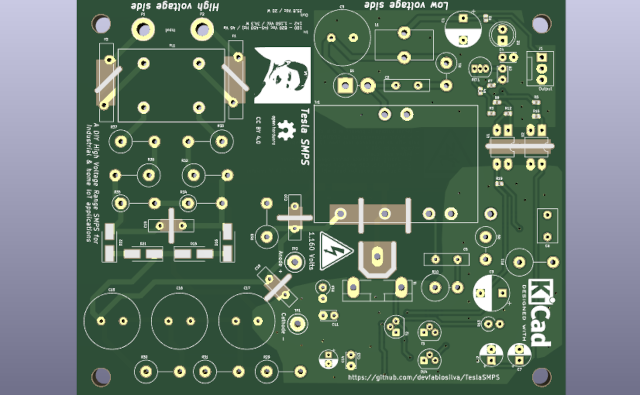
You can find PCB version in:
AC 100 ~ 820 Volts (45 - 450 Hz)
DC 142 ~ 1,160 Volts
DC 25.8 Volts (Insulated)
AC: 46 Va
DC: 34.3 W
0.78 @ 180 VDC / 127 VAC
0.70 @ 500 VDC / 350 VAC
0.65 @ 1,160 VDC / 820 VAC
0.75
3,600 Volts
42.6 Ampères @ 1,160 Volts
0.38 A^2-seconds
1.1 mH
933 mA
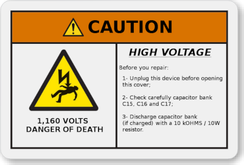
This power supply works with very high voltage input. Care MUST be taken to avoid any personal injuries or death
When power on high voltage, keep clear from input voltage cable.
For input voltages above 300 Vac/Vdc negative output MUST be grounded with 10 Ohms impedance or less
Keep in mind that this circuit stores high voltage even when power cord is off. If you want to repair or clear this SMPS wait at least 1 minute after remove power supply cord. Check test points TP1 (Cathode) and TP2 (Anode) pins with Voltimeter in scale 1,000 Vdc after touch or repair this circuit.
This device has security circuit for under voltage, short circuit and overload. When one of these events occurs, this SMPS will stop working and we need to disconnect power cord, remove the problem and then wait 30 seconds to turn on power cord again. NOTICE: NEVER touch or open this circuit if one of these events occurs EVEN if you disconnected this device from power cord.
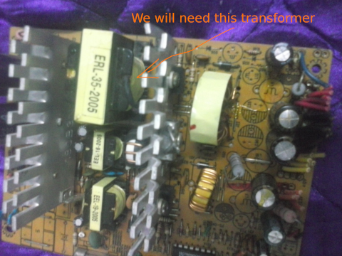
You will need to rewind the transformer following these steps
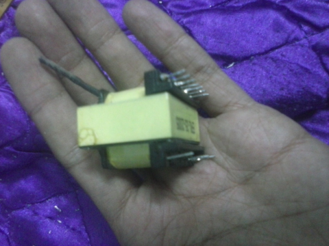
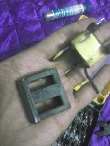
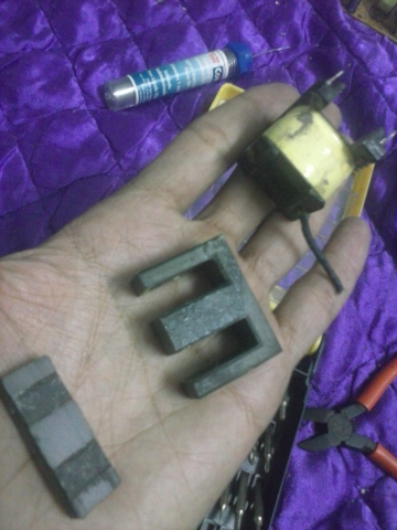
You can use a EI or EE type ferrite core
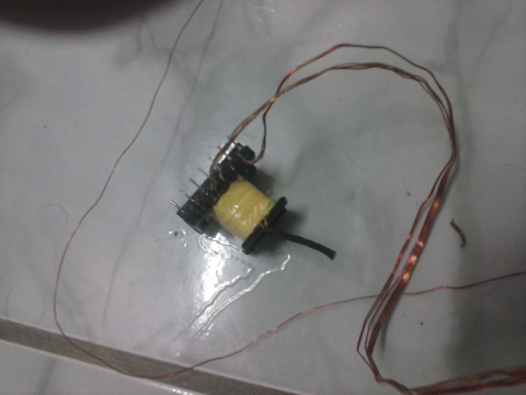
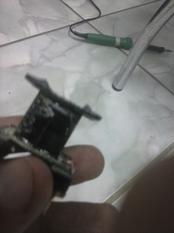
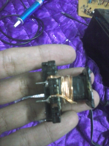
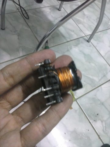
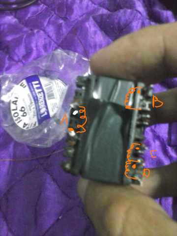
A - 4 turns (Secondary coil) (5 x 0.1 mm diameter *)
B - 30 turns (Primary coil) (3 x 0.05 mm diameter *)
C - 5 turns (Positive feedback coil) (0.1 mm diameter)
D - 4 turns (Control circuit supply) (0.1 mm diameter)
* Primary and secondary coil skin effect. Just interlace 3 x 0.05 mm copper wires and rewind the primary transformer spool and 5 x 0.1 mm copper wires in secondary coil
See example below:
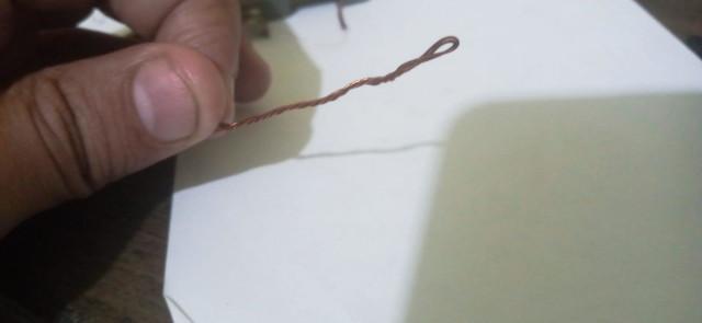
4 x 0.1mm interlaced wire
It is EXTREMELY IMPORTANT to insulate high voltage from secundary side. To do this you will need 6 layers of insulating tape to insulate 3.6 kV. Thus:
Transformer spool cross section example:
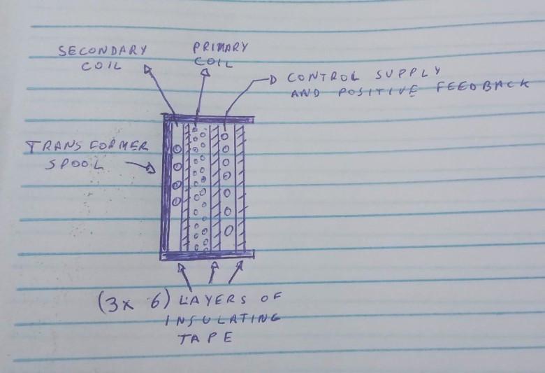
Primary coil winding
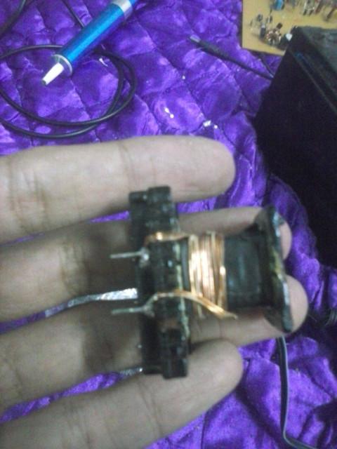
Control circuit supply and control circuit supply
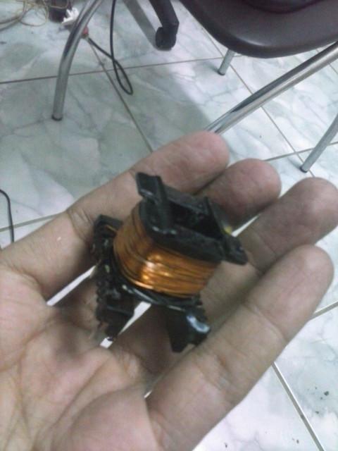
Finishing insulation
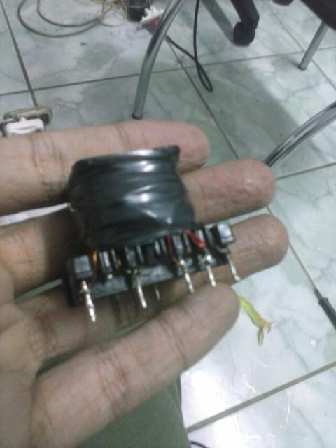
Flyback topology needs a core gap due to high peek flux to avoid saturation of the ferrite coil
So we need to create one approx. 120um core gap using a non magnetic material. E.g.: a piece of paper
Take a A4 paper
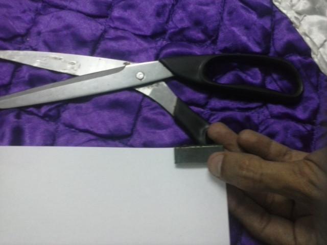
Cut a piece of paper
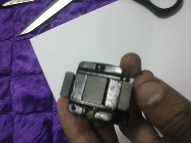
Fix the piece of paper in transforme core
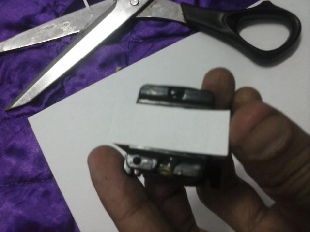
Close the transformer core
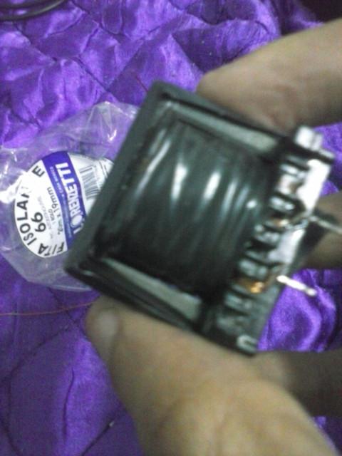
Finally your transformer is ready to work in your Tesla SMPS
Feel free to contact me at fabioegel@gmail.com
This project is sponsored by PCBWay
| Qty | Value | Footprint | References |
|---|---|---|---|
| 8 | 1N4007 | Diode_SMD:D_SMA_Handsoldering | D15, D16, D17, D18, D19, D20, D21, D22 |
| 8 | FR103 | Diode_SMD:D_SMA_Handsoldering | D3, D5, D7, D8, D9, D10, D11, D12 |
| 4 | 6R8/3W | Resistor_THT:R_Axial_DIN0516_L15.5mm_D5.0mm_P7.62mm_Vertical | R32, R33, R36, R37 |
| 4 | CP_Radial_D16.0mm_P7.50mm | Capacitor_THT:CP_Radial_D16.0mm_P7.50mm | C3, C15, C16, C17 |
| 3 | 100k/2W | Resistor_THT:R_Axial_DIN0516_L15.5mm_D5.0mm_P7.62mm_Vertical | R29, R30, R31 |
| 2 | 18k | Resistor_SMD:R_0402_1005Metric | R4, R24 |
| 2 | 220uF/35V | Capacitor_THT:CP_Radial_D8.0mm_P3.50mm | C1, C9 |
| 2 | 2N2222 | Package_TO_SOT_THT:TO-92 | T2, T3 |
| 2 | 2k2 | Resistor_SMD:R_0402_1005Metric | R3, R6 |
| 2 | 39k | Resistor_SMD:R_0402_1005Metric | R5, R14 |
| 2 | 3M3 | Resistor_THT:R_Axial_DIN0411_L9.9mm_D3.6mm_P7.62mm_Vertical | R34, R35 |
| 2 | 3k3 | Resistor_SMD:R_0402_1005Metric | R15, R25 |
| 2 | FR107 | Diode_SMD:D_SMA_Handsoldering | D4, D6 |
| 2 | Fuse | Fuse:Fuse_Bourns_MF-RHT1000 | F1, F2 |
| 2 | LTV-817 | Package_DIP:DIP-4_W7.62mm_LongPads | U1, U2 |
| 2 | NC | Capacitor_THT:C_Disc_D3.4mm_W2.1mm_P2.50mm | C4, C8 |
| 1 | 0 V | fmodules:1pin | TP1 |
| 1 | 0.22uF/25V | Capacitor_THT:CP_Radial_D4.0mm_P2.00mm | C14 |
| 1 | 1,160 Volts | fmodules:1pin | TP2 |
| 1 | 100R/1W | Resistor_THT:R_Axial_DIN0414_L11.9mm_D4.5mm_P5.08mm_Vertical | R1 |
| 1 | 100nF | Capacitor_THT:C_Disc_D3.4mm_W2.1mm_P2.50mm | C13 |
| 1 | 12V/0.4W | Diode_SMD:D_SOD-323F | D13 |
| 1 | 12k | Resistor_SMD:R_0402_1005Metric | R27 |
| 1 | 150R/5W | Resistor_THT:R_Axial_DIN0617_L17.0mm_D6.0mm_P7.62mm_Vertical | R11 |
| 1 | 150k | Resistor_SMD:R_0402_1005Metric | R28 |
| 1 | 180k | Resistor_SMD:R_0402_1005Metric | R17 |
| 1 | 1R/1W | Resistor_THT:R_Axial_DIN0414_L11.9mm_D4.5mm_P5.08mm_Vertical | R9 |
| 1 | 1R5/3W | Resistor_THT:R_Axial_DIN0614_L14.3mm_D5.7mm_P5.08mm_Vertical | R16 |
| 1 | 1k | Resistor_SMD:R_2010_5025Metric_Pad1.40x2.65mm_HandSolder | R22 |
| 1 | 1mH | Inductor_THT:L_Toroid_Vertical_L13.0mm_W6.5mm_P5.60mm | L1 |
| 1 | 1n5/2kV | Capacitor_THT:C_Disc_D10.0mm_W2.5mm_P5.00mm | C10 |
| 1 | 1nF/1kV | Capacitor_THT:C_Disc_D10.0mm_W2.5mm_P5.00mm | C5 |
| 1 | 22R | Resistor_SMD:R_0402_1005Metric | R21 |
| 1 | 22uF/25V | Capacitor_THT:CP_Radial_D5.0mm_P2.50mm | C12 |
| 1 | 27k | Resistor_SMD:R_0402_1005Metric | R19 |
| 1 | 27nF/400V | Capacitor_THT:C_Disc_D7.5mm_W4.4mm_P5.00mm | C6 |
| 1 | 2N5262 | Package_TO_SOT_THT:TO-92 | D14 |
| 1 | 2SK1317 | fmodules:F_TO-3P-3_Vertical | T1 |
| 1 | 2k2/(1/2W) | Resistor_THT:R_Axial_DIN0309_L9.0mm_D3.2mm_P2.54mm_Vertical | R13 |
| 1 | 2n2/2kV | Capacitor_THT:C_Disc_D10.0mm_W2.5mm_P5.00mm | C18 |
| 1 | 330R | Resistor_SMD:R_0402_1005Metric | R23 |
| 1 | 390R | Resistor_SMD:R_0402_1005Metric | R12 |
| 1 | 4k7 | Resistor_SMD:R_0805_2012Metric | R8 |
| 1 | 4k7/2W | Resistor_THT:R_Axial_DIN0617_L17.0mm_D6.0mm_P5.08mm_Vertical | R10 |
| 1 | 4n7/250V | Capacitor_THT:C_Disc_D10.0mm_W2.5mm_P5.00mm | C2 |
| 1 | 4n7/2kV | Capacitor_THT:C_Disc_D10.0mm_W2.5mm_P5.00mm | C19 |
| 1 | 4u7/35V | Capacitor_THT:CP_Radial_D5.0mm_P2.50mm | C7 |
| 1 | 6.8k | Resistor_SMD:R_0402_1005Metric | R26 |
| 1 | 6k8 | Resistor_SMD:R_0805_2012Metric | R2 |
| 1 | 820pF | Capacitor_THT:C_Disc_D3.4mm_W2.1mm_P2.50mm | C11 |
| 1 | 82k/3W | Resistor_THT:R_Axial_DIN0516_L15.5mm_D5.0mm_P7.62mm_Vertical | R18 |
| 1 | 8k2 | Resistor_SMD:R_0402_1005Metric | R20 |
| 1 | F_CHOKE | fmodules:F_CHOKE | FL1 |
| 1 | LOGO | fmodules:tesla | G*** |
| 1 | LOGO | fmodules:F_CAUTION_B | G*** |
| 1 | LOGO | fmodules:F_DANGER | G*** |
| 1 | Line1 | fmodules:F_PIN | P1 |
| 1 | Line2 | fmodules:F_PIN | P2 |
| 1 | NC | Resistor_SMD:R_0402_1005Metric | R7 |
| 1 | OUTPUT: 25.8 VDC/20 W | Connector:FanPinHeader_1x03_P2.54mm_Vertical | J1 |
| 1 | POWER | LED_THT:LED_D5.0mm | D2 |
| 1 | TL431LP | Package_TO_SOT_THT:TO-92_Inline | REF1 |
| 1 | Transformer | modules:F_TR | Tr1 |
| 1 | UF5404 | Diode_THT:D_DO-201AD_P5.08mm_Vertical_AnodeUp | D1 |
The 97 most common of 112 parts.
It measures 110.5 × 90.8 mm and has 2 copper layers, 1.6 mm thick.
112 parts, built around the LTV-817, FR103, FR107 and 2SK1317-E. The full list of its parts is on this page, with links to each part's symbol and footprint where PCBKit's library has them.
From the devfabiosilva/TeslaSMPS repository on GitHub, at the commit this page was made from: the board is 03-smd-project/tesla_smps.kicad_pcb and its schematic 03-smd-project/tesla_smps.kicad_sch. PCBKit opens the board in the browser, with nothing to install.
Its repository publishes it under the Unlicense licence: you may reuse it on that licence's terms (keep the author's notice, and for a copyleft licence share your changes alike).
MakerMylo/Embroiderino
Forked from an old gitlab repo to hold on to forever.

enriquewph/potenciatp4
Fuente Conmutada 50W 24V 2.4A de la cátedra Electrónica de Potencia - Grupo 3 - 5R2


EmanresuEmanreztuneb/SimpleFOC_G431_Motordriver
A motordriver based in STM's G431 Drone ESC.

maxime-leblan/Projet-VigiZone-E3-2026-ESIEE-Paris
VigiZone est un système de prévention anti-collision entre engins et piétons dans le BTP. Réalisé dans le cadre de notre projet de fin d'année en 1ère année du cycle ingénieur à ESIEE Paris.


MoElashmawi/Flyback-AC-DC-Converter
Flyback AC-DC Converter (230V AC to 12V DC) — Full SMPS design using VIPer22A PWM Controller. Schematic, PCB layout & 3D render in KiCad.
