6 layers100 × 100 mm
Usb power board
bluesatunsw/owr
This repo includes all software necessary to operate the Test Rover Platform that is being designed and developed in the 502 project.
409 parts5Apache-2.0

 deadbandlabs/syncro-mainboard
Hardware Design for Syncro FFB Interceptor
Syncro mainboard is an open-source printed circuit board by deadbandlabs, from the deadbandlabs/syncro-mainboard repository on GitHub, published under the CERN-OHL-W-2.0 licence. It is a 4-layer board of 78.5 × 59 mm with 158 parts on 222 nets, routed with 2,086 tracks and 359 vias.
It is built around the ECMF02-2AMX6, TPS25200DRVR and TS3USB221ARSER-HXY, with the EMIF06-MSD02N16, FE1.1S-BSOP28BCNTR and ESD5Z5.0 among its other parts. Its parts include 54 resistors, 29 capacitors, 18 diodes, 11 ICs and 9 connectors. It belongs with the computers and single-board computers boards of this library.


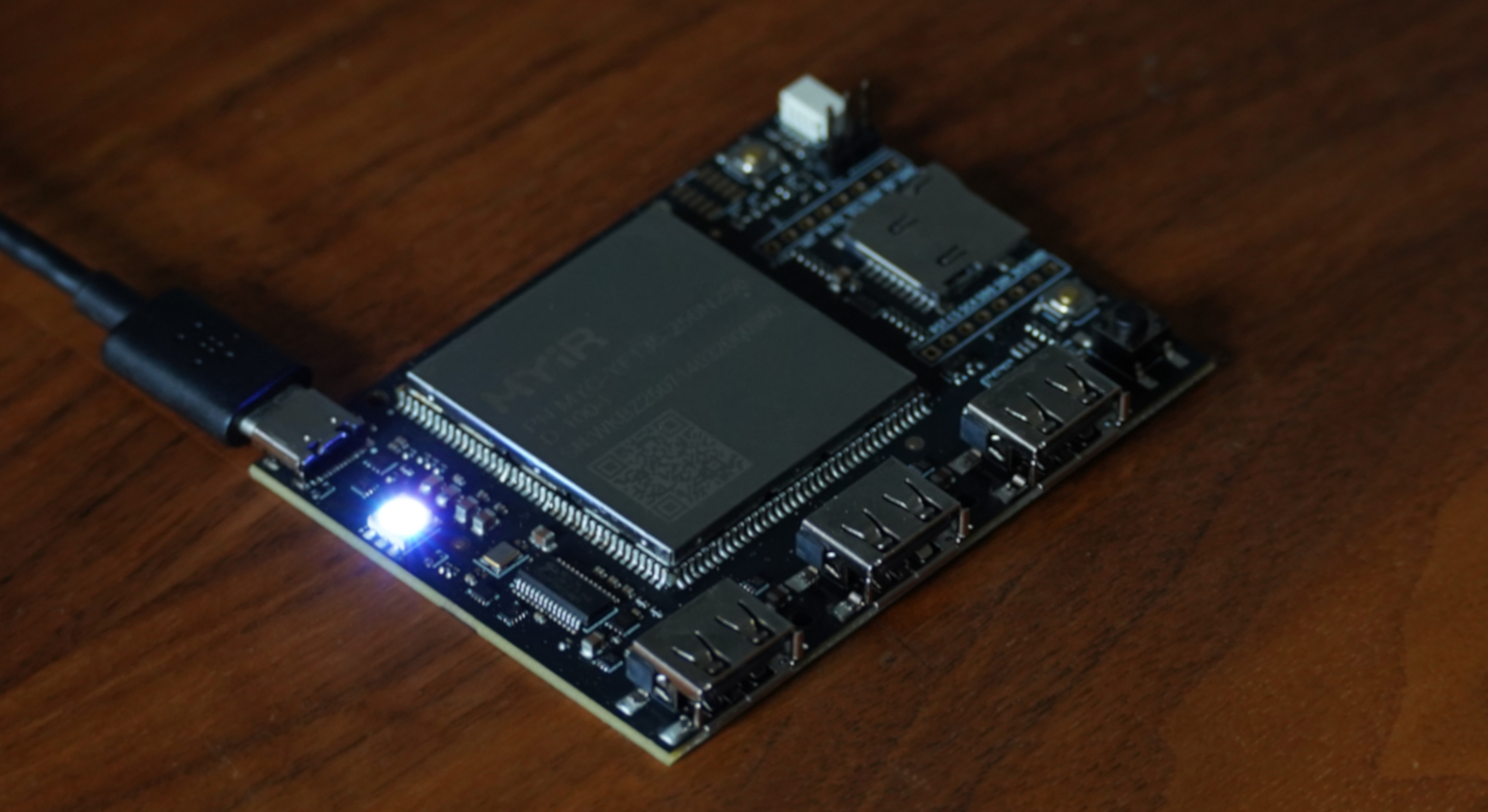 | 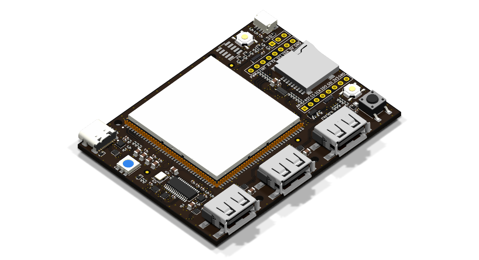 |
A USB HID force-feedback interceptor between a PC and FFB devices, based on the MYIR MYC-YF135 SOM (STM32MP135) and fully USB bus powered.
The board has three USB-A downstream ports, with a runtime-switched two-position topology mux:
The board also serves as an STM32MP13 development board, with Qwiic and mikroBUS (unpopulated) as GPIO expansion, SWD, UART debug header, user buttons and RGB status and accent LEDs.
Designed in KiCad 10. Open syncro-mainboard/syncro-mainboard.kicad_pro from a
clone of this repository. Libraries use paths relative to the project
(${KIPRJMOD}/../syncro-pcb-lib/), so no library setup is needed. Vendor
datasheets, vendor 3D models, fabrication outputs and internal DFT tools are not
included. As a result, missing-3D-model warnings are expected. This does not affect
the schematic, layout, DRC or plots.
Part numbers as assembled are in the LCSC fields on the schematic symbols.
JST SH 1.0 mm, 4 pin, horizontal: GND, 3V3, SDA (PF3) and SCL (PH13),
both on I2C5 and shared with the mikroBUS socket, with 10 kOhm pull-ups fitted.
Qwiic modules usually also provide pull-ups, so a long chain may over-pull the bus.
Prefer a module without pull-ups or drop bus speed to 100 kHz.
Standard mikroBUS pinout on two 1x8 sockets at 22.86 mm row spacing. All 12 IO signals route to SOM GPIO, chosen for the roles below:
| Pin | mikroBUS | Board net | SOM pad | SOM port | Roles |
|---|---|---|---|---|---|
| 1 | AN | AIO1 | 48 | PA1 | ADC1/2_INP3, TIM2_CH2, TIM5_CH2, TIM15_CH1N |
| 2 | RST | RST | 92 | PA5 | ADC1_INP2, TIM2_CH1 |
| 3 | CS | SPI_CS | 80 | PA4 | SPI1, ADC1_INP14, ClickID 1-Wire |
| 4 | SCK | SPI_SCK | 79 | PC3 | SPI1, I2S1_CK, ADC1_INP13 |
| 5 | MISO | SPI_MISO | 77 | PA6 | SPI1, ADC1_INP17, TIM3_CH1, TIM13_CH1 |
| 6 | MOSI | SPI_MOSI | 78 | PA3 | SPI1, I2S1_SDO, ADC1_INP12 |
| 7 | 3V3 | 3V3 | 16 | - | keep under 100 mA, no limit |
| 8 | GND | GND | - | - | |
| 9 | PWM | AIO0 | 47 | PA2 | ADC1/2_INP1, TIM2_CH3, TIM5_CH3, TIM15_CH1 |
| 10 | INT | INT | 91 | PF11 | ADC1/2_INP8 |
| 11 | RX | CAN_RX | 96 | PB5 | FDCAN2, UART5_RX, TIM3_CH2 |
| 12 | TX | CAN_TX | 95 | PB13 | FDCAN2, UART5_TX, LPTIM2_OUT |
| 13 | SCL | I2C_SCL | 133 | PH13 | I2C5 |
| 14 | SDA | I2C_SDA | 132 | PF3 | I2C5 |
| 15 | 5V | SYS_5V | - | - | board 5 V rail |
| 16 | GND | GND | - | - |
AN and PWM use a 330 Ohm series resistor, remaining GPIO 33 Ohm
for protection. All pins share two 0.3 pF ESD arrays. RX/TX
for UART5 also support FDCAN2 directly, so a CAN transceiver Click should work.
| J2 pin | Signal |
|---|---|
| 1 | GND |
| 2 | UART4_TX |
| 3 | UART4_RX |
J3 is a standard ARM Cortex Debug 10-pin, 1.27 mm: pin 1 VTref on VDD_3V3,
SWDIO/SWCLK plus reset.
SDMMC1 via an EMIF06-MSD02N16, which provides series resistance, filter
capacitance, ESD and card detect on SOM pad 110 (PD12). Normally empty, meant
for development or as an alternate boot target using a cut trace on the bottom
of the board.
USB-A's ~250 mA limit leaves about 400 mA for the SOM (measured 128 mA average, ~160 mA peak), the hub (30-80 mA) and everything else, inside the 647 mA nominal input eFuse limit (590-710 mA over tolerance, 150 kOhm ILIM). A PC USB 2.0 port generally only guarantees 500 mA, so downstream devices should be self-powered for best reliability.
GPIO peripherals are powered from the SOM's 3V3 output, shared with the rest of the board and with no limiting eFuse on these pins. Keep the total under 100 mA to avoid brownout.
The board's OS (TF-A, OP-TEE, U-Boot, Linux kernel and rootfs) is built with the Deadband Labs Buildroot SDK: https://github.com/deadbandlabs/dbl-buildroot. It builds a complete image from upstream sources that boots the MYIR SOM, with console, USB gadget and host, SPI NAND and SD card enabled in the device tree.
dbl-buildroot is designed to be extended by a parent project: a device tree
include applied on top of the base tree, plus a BR2_EXTERNAL tree adding
packages, overlays and defconfigs, see its
Parent Integration
page. Carrier board peripherals (USB hub control, Qwiic and I2C, mikroBUS and so
on) are implemented this way. The Syncro userspace and its board layer are
pending final publication and will be linked here when complete.
Design files: CERN-OHL-W-2.0, see LICENSE and NOTICE.
A design using the board only through its external interfaces (USB ports, Qwiic, mikroBUS/Click, console serial header and SWD) is External Material under section 1.8 of the licence and does not need to be released. Modified design files must be published under the same licence.
syncro-pcb-lib/ is generated from the project's parts library (see
syncro-pcb-lib/GENERATED.md), and part of it derives from stock KiCad libraries,
which stay CC-BY-SA-4.0 with the KiCad libraries exception. See NOTICE.
| Qty | Value | Footprint | References |
|---|---|---|---|
| 16 | 100n | Capacitor_SMD:C_0402_1005Metric | C5, C6, C7, C8, C9, C13, C15, C18, C19, C21, C25, C26, C27, C28, C29, C30 |
| 12 | ESD5Z5.0 | Diode_SMD:D_SOD-523 | D1, D2, D3, D4, D5, D6, D7, D8, D9, D10, D11, D13 |
| 10 | 33 | Resistor_SMD:R_0402_1005Metric | R19, R20, R36, R37, R38, R39, R42, R43, R44, R45 |
| 10 | 330 | Resistor_SMD:R_0402_1005Metric | R15, R16, R28, R34, R35, R40, R41, R50, R53, R56 |
| 7 | 10u | Capacitor_SMD:C_0805_2012Metric | C3, C4, C16, C20, C22, C23, C24 |
| 6 | 100 | Resistor_SMD:R_0402_1005Metric | R14, R17, R18, R21, R22, R31 |
| 6 | 2.2k | Resistor_SMD:R_0402_1005Metric | R23, R24, R25, R49, R52, R55 |
| 5 | 10k | Resistor_SMD:R_0402_1005Metric | R6, R12, R13, R46, R47 |
| 4 | 510 | Resistor_SMD:R_0402_1005Metric | R30, R48, R51, R54 |
| 4 | ECMF02-2AMX6 | dbl-ic:ST_UQFN-6L_1.5x1.7mm_P0.5mm | U4, U8, U9, U10 |
| 4 | MountingHole_2.2mm_M2_ISO7380 | MountingHole:MountingHole_2.2mm_M2_ISO7380 | , , , |
| 3 | 100k | Resistor_SMD:R_0402_1005Metric | R1, R2, R26 |
| 3 | 1k | Resistor_SMD:R_0402_1005Metric | R3, R11, R29 |
| 3 | Fiducial_1mm_Mask2mm | dbl-mech:Fiducial_1mm_Mask2mm | , , |
| 3 | USB_A | dbl-mech:USB_A_SHOUHAN_10.0-QTJ6.3_Horizontal | J5, J6, J7 |
| 3 | XL-1615RGBC-RF | dbl-ic:LED_RGB_XINGLIGHT_XL-1615RGBC | D16, D17, D18 |
| 2 | 1u | Capacitor_SMD:C_0402_1005Metric | C12, C14 |
| 2 | 20p | Capacitor_SMD:C_0402_1005Metric | C10, C11 |
| 2 | 22u | Capacitor_SMD:C_0805_2012Metric | C1, C2 |
| 2 | 5.1k | Resistor_SMD:R_0402_1005Metric | R4, R5 |
| 2 | BDFN3310A056R | dbl-ic:BDFN3310-10_3.3x1.0mm_P0.4mm | D14, D15 |
| 2 | TPS25200 | dbl-ic:WSON-6-1EP_2x2mm_P0.65mm_EP1x1.6mm_ThermalVias_0.3mm | U6, U11 |
| 2 | TS3USB221ARSER | dbl-ic:Texas_UQFN-10_1.5x2mm_P0.5mm | U2, U3 |
| 1 | 10k 5% | Resistor_SMD:R_0402_1005Metric | R27 |
| 1 | 12MHz | Crystal:Crystal_SMD_3225-4Pin_3.2x2.5mm | Y1 |
| 1 | 150k 1% | Resistor_SMD:R_0402_1005Metric | R9 |
| 1 | 2.7k 1% | Resistor_SMD:R_0402_1005Metric | R7 |
| 1 | 300k | Resistor_SMD:R_0402_1005Metric | R8 |
| 1 | 390k 1% | Resistor_SMD:R_0402_1005Metric | R32 |
| 1 | 3V3 | TestPoint:TestPoint_Pad_D1.5mm | TP2 |
| 1 | 3V3P | TestPoint:TestPoint_Pad_D1.5mm | TP8 |
| 1 | 5V | TestPoint:TestPoint_Pad_D1.5mm | TP1 |
| 1 | AO3401A | Package_TO_SOT_SMD:SOT-23 | Q1 |
| 1 | BOOT0 | TestPoint:TestPoint_Pad_D1.5mm | TP18 |
| 1 | BOOT1 | TestPoint:TestPoint_Pad_D1.5mm | TP17 |
| 1 | BOOT2 | TestPoint:TestPoint_Pad_D1.5mm | TP16 |
| 1 | BRD_A | TestPoint:TestPoint_Pad_D1.5mm | TP19 |
| 1 | BRD_B | TestPoint:TestPoint_Pad_D1.5mm | TP20 |
| 1 | BTN | TestPoint:TestPoint_Pad_D1.5mm | TP21 |
| 1 | Conn_01x03 | Connector_PinHeader_2.54mm:PinHeader_1x03_P2.54mm_Vertical | J2 |
| 1 | Conn_ARM_JTAG_SWD_10 | Connector_PinSocket_1.27mm:PinSocket_2x05_P1.27mm_Vertical_SMD | J3 |
| 1 | DM | TestPoint:TestPoint_Pad_D1.5mm | TP6 |
| 1 | DP | TestPoint:TestPoint_Pad_D1.5mm | TP5 |
| 1 | EMIF06-MSD02N16 | dbl-ic:EMIF06-MSD02N16_uQFN-16_3.5x1.2mm_P0.4mm | U7 |
| 1 | FE1.1s | Package_SO:SSOP-28_3.9x9.9mm_P0.635mm | U5 |
| 1 | GND | TestPoint:TestPoint_Pad_D1.5mm | TP4 |
| 1 | LED_GRB | LED_SMD:LED_RGB_5050-6 | D12 |
| 1 | MODE | TestPoint:TestPoint_Pad_D1.5mm | TP3 |
| 1 | MYC-YF135 | dbl-ic:MYC-YF135 | U1 |
| 1 | Micro_SD_Card_Det1 | dbl-mech:microSD_SHOUHAN_TF-CARD-H1.8-SY | J4 |
| 1 | MikroBUS | dbl-mech:MikroBUS_Socket_2x1x08_P2.54mm | J8 |
| 1 | Qwiic | dbl-mech:JST_SH_SM04B-SRSS-TB_1x04-1MP_P1.00mm_Horizontal | J9 |
| 1 | RESET | dbl-mech:SW_Push_1P1T_XKB_TS-1187A | SW1 |
| 1 | RST | TestPoint:TestPoint_Pad_D1.5mm | TP15 |
| 1 | RX | TestPoint:TestPoint_Pad_D1.5mm | TP11 |
| 1 | SD BOOT | Jumper:SolderJumper-2_P1.3mm_Bridged_RoundedPad1.0x1.5mm | JP2 |
| 1 | SWCLK | TestPoint:TestPoint_Pad_D1.5mm | TP13 |
| 1 | SWDIO | TestPoint:TestPoint_Pad_D1.5mm | TP14 |
| 1 | SW_USER | Button_Switch_SMD:SW_Push_1P1T_NO_E-Switch_TL3301NxxxxxG | SW3 |
| 1 | TX | TestPoint:TestPoint_Pad_D1.5mm | TP12 |
| 1 | USB BOOT | dbl-mech:SW_Push_1P1T_XKB_TS-1187A | SW2 |
| 1 | USBEN | TestPoint:TestPoint_Pad_D1.5mm | TP10 |
| 1 | USB_C_Receptacle_USB2.0_16P | dbl-mech:USB_C_Receptacle_SHOUHAN_TYPE-C-16PIN-2MD-073 | J1 |
| 1 | VBAT | Jumper:SolderJumper-2_P1.3mm_Bridged_RoundedPad1.0x1.5mm | JP1 |
| 1 | VBUS | TestPoint:TestPoint_Pad_D1.5mm | TP7 |
| 1 | VUSB | TestPoint:TestPoint_Pad_D1.5mm | TP22 |
The 156 most common of 158 parts.
It measures 78.5 × 59 mm and has 4 copper layers, 1.63 mm thick.
158 parts, built around the ECMF02-2AMX6, TPS25200DRVR, TS3USB221ARSER-HXY and EMIF06-MSD02N16. The full list of its parts is on this page, with links to each part's symbol and footprint where PCBKit's library has them.
From the deadbandlabs/syncro-mainboard repository on GitHub, at the commit this page was made from: the board is syncro-mainboard/syncro-mainboard.kicad_pcb and its schematic syncro-mainboard/accessory.kicad_sch. PCBKit opens the board in the browser, with nothing to install.
Its repository publishes it under the CERN-OHL-W-2.0 licence: you may reuse it on that licence's terms (keep the author's notice, and for a copyleft licence share your changes alike).
bluesatunsw/owr
This repo includes all software necessary to operate the Test Rover Platform that is being designed and developed in the 502 project.

taseraul/schrodinger-studio
Portable mixer with microphone preamp, bluetooth input, battery management, lighting system and modular design.


bartsil/Mini-AI-Camera-Module
Mini AI Camera Module based on ESP32-S3 for IoT and robotic projects


beaked99/air-scales
2025-11-20. Updated all the footprints and symbols to their proper layouts. no more fkn errors. Hallefuckinglujah. Fucked up with LM74610 not using the right footprint. minor fix. 2025-11-16.