4 layers
 bartsil/Mini-AI-Camera-Module3
Mini AI Camera Module based on ESP32-S3 for IoT and robotic projects
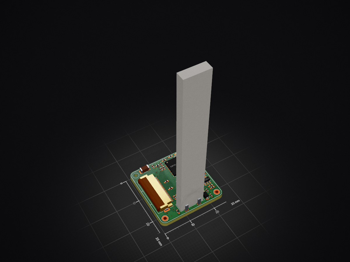
Mini AI Camera Module is an open-source printed circuit board by bartsil, from the bartsil/Mini-AI-Camera-Module repository on GitHub, published under the Apache-2.0 licence. It is a 4-layer board of 25 × 25 mm with 68 parts on 73 nets, routed with 504 tracks and 84 vias.
It is built around the ESP32-S3FH4R2, AP63203WU and CH213K, with the ESD5Z5.0 among its other parts. Its parts include 29 capacitors, 14 resistors, 6 ICs, 3 diodes and 2 connectors. It belongs with the ESP32 boards of this library.


The Mini AI Camera Module is a compact platform based on the ESP32-S3, combining a standard visible-light camera with a LiDAR sensor. The module is designed as a low-cost solution for implementing simple AI algorithms, image recognition, and basic 3D depth perception.
This project includes:
(A future hardware revision is planned to include the VL53L9CX sensor featuring a 54×42 pixel resolution.)
Compact size: 25×25 mm
The module includes mounting holes for easy installation, e.g., in mobile robots.
Two complementary imaging systems
Low production cost
Ideal for autonomous and IoT projects
Suitable for robotics, autonomous vehicles, perception systems, and IoT devices.
Wireless connectivity
With the ESP32-S3, the module supports:
Convenient USB and UART interfaces
Easy to use and based on open-source libraries
The project is designed to be simple to integrate and develop with. It relies on well-maintained open-source libraries (including SparkFun drivers) as well as built-in components from the ESP-IDF framework.
Open-source project (Apache 2.0 License)
The entire project is fully open-source and released under the Apache 2.0 license, allowing both personal and commercial use with minimal restrictions.
| Qty | Value | Footprint | References |
|---|---|---|---|
| 10 | 100nF | Capacitor_SMD:C_0402_1005Metric_Pad0.74x0.62mm_HandSolder | C5, C9, C12, C13, C26, C29, C30, C34, C35, C37 |
| 7 | 4.7uF | Capacitor_SMD:C_0402_1005Metric_Pad0.74x0.62mm_HandSolder | C3, C4, C18, C19, C27, C28, C33 |
| 5 | 4.7k | Resistor_SMD:R_0402_1005Metric_Pad0.72x0.64mm_HandSolder | R4, R5, R10, R11, R15 |
| 4 | 47k | Resistor_SMD:R_0402_1005Metric_Pad0.72x0.64mm_HandSolder | R1, R2, R3, R8 |
| 3 | 10k | Resistor_SMD:R_0402_1005Metric_Pad0.72x0.64mm_HandSolder | R9, R12, R13 |
| 3 | MountingHole | Moje_Footprinty:MountingHole_1.1mm_M1_DIN965_Pad | H2, H3, H4 |
| 2 | 10uF | Capacitor_SMD:C_0402_1005Metric_Pad0.74x0.62mm_HandSolder | C15, C21 |
| 2 | 22uF | Capacitor_SMD:C_0402_1005Metric | C7, C10 |
| 2 | 22uF | Capacitor_SMD:C_0402_1005Metric_Pad0.74x0.62mm_HandSolder | C31, C32 |
| 2 | 5.1k | Resistor_SMD:R_0402_1005Metric_Pad0.72x0.64mm_HandSolder | R6, R7 |
| 1 | 100nF | Capacitor_SMD:C_0402_1005Metric | C8 |
| 1 | 120R-1.3A | Resistor_SMD:R_0402_1005Metric_Pad0.72x0.64mm_HandSolder | FB1 |
| 1 | 15pF | Capacitor_SMD:C_0402_1005Metric_Pad0.74x0.62mm_HandSolder | C36 |
| 1 | 1uF | Capacitor_SMD:C_0402_1005Metric_Pad0.74x0.62mm_HandSolder | C11 |
| 1 | 1uF | Capacitor_SMD:C_0402_1005Metric | C6 |
| 1 | 4.7pF | Capacitor_SMD:C_0402_1005Metric | C2 |
| 1 | 4.7uF | Moje_Footprinty:L_2016 | L2 |
| 1 | 5.6nH/3.0nH | Inductor_SMD:L_0402_1005Metric | L1 |
| 1 | AP63203WU | Package_TO_SOT_SMD:TSOT-23-6 | U7 |
| 1 | Antenna_Ceramic | Capacitor_SMD:C_1206_3216Metric | AE1 |
| 1 | CH213K | Package_TO_SOT_SMD:SOT-23 | U3 |
| 1 | Conn_Camera | Moje_Footprinty:Hirose_FH12-24S-0.5SH_1x24-1MP_P0.50mm_Horizontal_WithCamera_BackSide_Opt1 | J2 |
| 1 | ESD5Z5.0 | Diode_SMD:D_SOD-523 | D2 |
| 1 | ESP32-S3FH4R2 | Moje_Footprinty:QFN-56-1EP_7x7mm_P0.4mm_EP4x4mm_ThermalVias_ESP32 | U2 |
| 1 | LED | LED_SMD:LED_0402_1005Metric_Pad0.77x0.64mm_HandSolder | D4 |
| 1 | LOGO | Moje_Footprinty:LOGO-KI_5mm | G*** |
| 1 | MountingHole | Moje_Footprinty:MountingHole_1.1mm_M1_No_Pad | H1 |
| 1 | NC | Capacitor_SMD:C_0402_1005Metric | C1 |
| 1 | RT9193-1V2 | Package_TO_SOT_SMD:SOT-23-5 | U5 |
| 1 | RT9193-2V8 | Package_TO_SOT_SMD:SOT-23-5 | U6 |
| 1 | SBR3U40S1F-7 | Diode_SMD:D_SOD-123 | D1 |
| 1 | SW_Flash | Moje_Footprinty:SW_Push_3.0x4.0mm | SW2 |
| 1 | SW_Reset | Moje_Footprinty:SW_Push_3.0x4.0mm | SW1 |
| 1 | TestPoint_3V3 | TestPoint:TestPoint_Pad_1.0x1.0mm | TP3 |
| 1 | TestPoint_GND | TestPoint:TestPoint_Pad_1.0x1.0mm | TP2 |
| 1 | TestPoint_VIN | TestPoint:TestPoint_Pad_1.0x1.0mm | TP1 |
| 1 | USB_C_Vertical | Moje_Footprinty:USB_C_Hanbo Electronic MC-118LD-H65 | J1 |
| 1 | VL53L5CX-Sensor_Distance | Moje_Footprinty:ST_VL53L5CX_HandSoldering | U1 |

deadbandlabs/syncro-mainboard
Hardware Design for Syncro FFB Interceptor


beaked99/air-scales
2025-11-20. Updated all the footprints and symbols to their proper layouts. no more fkn errors. Hallefuckinglujah. Fucked up with LM74610 not using the right footprint. minor fix. 2025-11-16.

schmidtmt/openmotorbridge
The comprehensive technical specification is split into 18 logically organized chapters:

nodestark/mdb-esp32-cashless
ESP32-based MDB cashless device for vending machines, supporting EVA DTS DEX/DDCMP telemetry and payments over the MDB protocol via Bluetooth and MQTT

fellettigiacomo/esp32-WLED-4ch-controller
Open source 4 Channel esp32-powered WLED controller with 4 relays and built in level shifter

It measures 25 × 25 mm and has 4 copper layers, 1.6 mm thick.
68 parts, built around the ESP32-S3FH4R2, AP63203WU, CH213K and ESD5Z5.0. The full list of its parts is on this page, with links to each part's symbol and footprint where PCBKit's library has them.
From the bartsil/Mini-AI-Camera-Module repository on GitHub, at the commit this page was made from: the board is PCB/KiCad/PCB.kicad_pcb and its schematic PCB/KiCad/PCB.kicad_sch. PCBKit opens the board in the browser, with nothing to install.
Its repository publishes it under the Apache-2.0 licence: you may reuse it on that licence's terms (keep the author's notice, and for a copyleft licence share your changes alike).