
2 layers21.1 × 26.9 mm

 danko-david/uartbus6
A library that turns microcontroller's UART peripheral to a simple, multi-master bus system. The project also features an RPC library for a microcontroller, device auto-discovery, code upload, gateway between the bus and PC, java code to manage microcontroller's RPC on a higher level of abstraction.
UB AT328 proto is an open-source printed circuit board by danko-david, from the danko-david/uartbus repository on GitHub, published under the MIT licence. It is a 2-layer board of 61 × 40.6 mm with 32 parts on 108 nets, routed with 134 tracks and 0 vias.
It is built around the BS170. It belongs with the interfaces and adapters boards of this library.
The project goal is to connect microcontrollers together on wire at minimal cost (wiring, external peripheral components) and build a decentralized sensor-actuator network where the node's can interact with each other and the microcontroller's software can be upgraded from the bus. This bus should be connectable to a computer system (Desktop/Server PC, Raspberry PI, etc) to achieve complex controlling by interacting with the sensors, actuators with higher level softwares.
The way to satisfy these requirement is to design and implement:
** Features related to bus: **
** Features related to the infrastructure: **
app_wrapper used to compile applications can be uploaded to a node.
TODO compiler, source, etcping to ping nodes, console to send command to
devices, packetloss to measure packet loss ratio between bus gateway
and node, collisionPacketloss to measure packet loss and duplication
when send a broadcast packets that results race to access the bus.
upload upload application code to a device with has uartbus bootloader on
the board.TODO: There's an easier way to try it out by yourself, using only arduino and generic FETs (or BJTs with no opening delay in switching mode)
See: Documentation index
All level and detail are implemented as small portion and bound so loosely
together to anyone can reuse the smaller piece of building blocks for custom
project.
Eg: you can use OSI-{1,2} levels and skip the upper ones and create a message based bus like as the CAN bus works. Or reverse: use CAN on the lowest level and use the infrastructure.
The bus data line consist of one wire pulled up to the bus Vcc voltage. This line can be pulled down by any node used to transfer data.
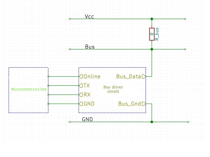
The microcontroller's UART port is connected to the bus using bus driver:
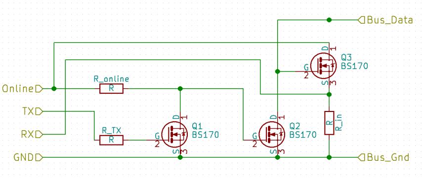
(During the development: Vcc = 12V; Rbus = 500Ω; Rtx = 0Ω;
Rin & Ronline = 10 KΩ; 120m twisted pair for GND and Bus wire; 115,2 kbps)
(Note: this BS170 tolerates ±20V of Ugs voltage so can be connected directly to
the bus wire, but this might be risky when dealing with high transient voltage.
Solution: Connect TVS diode between Bus and GND wire. See documentation)
This is a simple level driver which makes the byte sent on the TX port appears
in the Bus line and data appears on the Bus wire translated to the RX port
with the proper logic level. This also means what we send on the TX we receive
on the RX. This used for transmission error and collision detection.
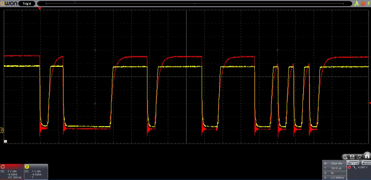
In this context, packet is interpreted as a sequence of byte in a time frame. The time frame starts at the first sent byte and ends after the time of 2 (default value, but configurable) byte time transmission idle period.
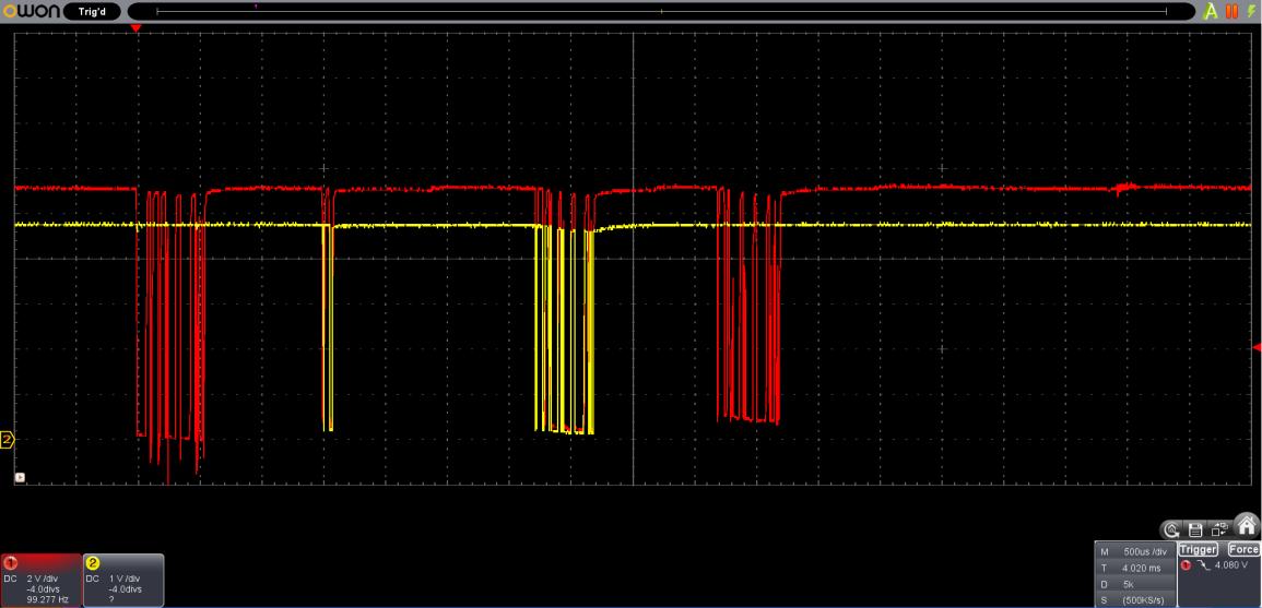
A demonstration of UARTBus packages with collision handling (and retransmission) using two nodes plus one bus gateway. (This is an early development oscillogramm, timing not properly optimized)
Every node receives every packets on bus. This makes possible to create broadcast addresses (0 is a general broadcast address) and device groups by using negative addresses for this purpose.
Instead of using fixed int{8,16,32,64}_t for addressing, i've created a so called variable length addressing:
To balance between this extreme cases i've created an encoder/decoder that enables short address bytes when addresses are low (between -64 and +63) and increase address length when assign higher addresses.
| 7. bit | 6. bit | 5. bit | 4. bit | 3. bit | 2. bit | 1. bit | 0. bit | |
|---|---|---|---|---|---|---|---|---|
| First byte | E | S | A5 | A4 | A3 | A2 | A1 | A0 |
| Nth byte | E | A6 | A5 | A4 | A3 | A2 | A1 | A0 |
Byte scheme:
Example for one byte addresses:
| Address | First byte |
|---|---|
| 0 | 0000_0000 |
| -1 | 0100_0000 |
| 16 | 0001_0000 |
| -16 | 0100_1111 |
| -64 | 0111_1111 |
| 63 | 0011_1111 |
Example for two byte addresses:
| Address | First byte | Second byte |
|---|---|---|
| 128 | 1000_0001 | 0000_0000 |
| -128 | 1100_0000 | 0111_1111 |
| 8191 | 1011_1111 | 0111_1111 |
| -8192 | 1111_1111 | 0111_1111 |
These types described as (s)vint_t (signed variable int) but it is not a real type which the compiler knows, just a notation. (There's an implementation for uvint_t if you use only unsigned values.)
The default packet scheme of the project:
All packets are datagrams. There's no transmission control mechanism implemented yet.
I've created a small footprint RPC library for microcontrollers. The namespace path and function parameters just placement in the packet after each other. The dispatcher function relays the request to the proper RPC path, and the registered RPC call handler extracts the parameters executes the query and responses the packet.
A request parsed into a struct rpc_request located in
./source/uc/utils/lib/rpc/rpc.h.
This request is dispatched through a RPC namespace chain. For example see: ./source/uc/bootloader/ub_bootloader.c how RPC_NS_FUNCTIONS constructed and where this chain used as a parameter.
When a namespace matched procPtr incremented, so in next processing stage
the it will be continued from the next byte (pointed in the payload by
the procPtr which is incremented right now)
The pointed function may dispatch again, or it can be a function which processes
the request. The reply function pointer in the struct rpc_request used
assemble and send response packet.
Example: in the bootloader (aka: uart host application) there's some pre-defined RPC namespace and functions which provides unified functionality for all devices on the bus.
And so on, for full namespace specification see documentation.
To turn on the user led you have to send a packet with payload of:
1:2:1 => (1) Bus functions => (2) user led handler function => (1) parameter
this returns with the response:
0:1:2:1 => (0) response packet => (1:2) namespace and function path => (1)
response parameter aka the led is turned on.
To invoke a hardware reset:
2:0:0 => (2) Bootloader functions => (0) power functions => (0) hardware reset
No response generated, because committed a hardware reset immediately.
This namespace tree is extendible to any depth, and designed to the application developer can attach new function into this tree.
At the other side, on the PC in java, this RPC namespace tree is modeled with
objects, see: UartBusDevice.getRpcRoot() . But the best thing: i've created
a mechanism to describe interfaces for this RPC namespaces and functions with
the known types, and java (using proxies) generates namespace object and
function you can call right from java. For example see: UbBootloaderFunctions
and for a real application that uses this see: UartbusCodeUploader
In the directory .source/uc/bootloader/ you find the source of the bootloader (the naming is wrong, it's more likely be called as uart host application) This implements the basic unified functionality described earlier and also makes possible to manage application code upload.
| Qty | Value | Footprint | References |
|---|---|---|---|
| 5 | Conn_01x14 | Connector_PinSocket_2.54mm:PinSocket_1x14_P2.54mm_Vertical | , , , , |
| 4 | CONN_01X08 | Connector_PinHeader_2.54mm:PinHeader_1x08_P2.54mm_Vertical | , , , |
| 4 | CONN_01X12 | Connector_PinHeader_2.54mm:PinHeader_1x12_P2.54mm_Vertical | , , , |
| 4 | Jumper_NO_Small | Jumper:SolderJumper-2_P1.3mm_Open_TrianglePad1.0x1.5mm | JP_Supply_from_bus, JP_Supply_from_regulator, JP_Supply_to_circuit, JP_Supply_VCC |
| 4 | R | Resistor_THT:R_Axial_DIN0204_L3.6mm_D1.6mm_P2.54mm_Vertical | R_in, R_online, R_sImax, R_TX |
| 3 | BS170 | Package_TO_SOT_THT:TO-92L_Inline | Q_Inv, Q_RX, Q_TX |
| 1 | 7805 | Package_TO_SOT_THT:TO-220-3_Vertical | 78xx |
| 1 | CONN_01X03 | Connector_PinHeader_2.54mm:PinHeader_1x03_P2.54mm_Vertical | Bus_pin |
| 1 | CONN_01X04 | Connector_PinHeader_2.54mm:PinHeader_1x04_P2.54mm_Vertical | |
| 1 | D_TVS | Diode_THT:D_DO-34_SOD68_P2.54mm_Vertical_AnodeUp | TVS |
| 1 | Polyfuse | Resistor_THT:R_Axial_DIN0204_L3.6mm_D1.6mm_P2.54mm_Vertical | Fuse |
| 1 | RJ12 | Connector_RJ:RJ12_Amphenol_54601 | RJ11 |
| 1 | Screw_Terminal_1x02 | TerminalBlock:TerminalBlock_bornier-2_P5.08mm | Power wire |
The 31 most common of 32 parts.
It measures 61 × 40.6 mm and has 2 copper layers, 1.6 mm thick.
32 parts, built around the BS170. The full list of its parts is on this page, with links to each part's symbol and footprint where PCBKit's library has them.
From the danko-david/uartbus repository on GitHub, at the commit this page was made from: the board is electronic/kicad/bus_connector_schematics/UB_AT328_proto.kicad_pcb. PCBKit opens the board in the browser, with nothing to install.
Its repository publishes it under the MIT licence: you may reuse it on that licence's terms (keep the author's notice, and for a copyleft licence share your changes alike).


pablozg/freeds
Derivador de energía solar excedente creado por Pablo Zerón, Diseño PCB por Amcalo, Tester original por Aeizoon, Wiki por Zoilo Mora

PhysicsDptAngers/polyUAnalog
Open source, analog and polyphonic synthesizer


DRWJSCHMIDT/T41
This is the repository for the officially released V10, V11, and V12 versions of the T41 Software Defined Transceiver hardware and kits.

sffubs/dactyl_manuform_gimbal
Instrutions and designs for building the dactyl-manuform-gimbal keyboard