
2 layers55.5 × 33.7 mm

A simple four port USB-DMX ArtNET-Node
DMX is an open-source printed circuit board by CShark, from the CShark/Lumen-ArtNode repository on GitHub. It is a 4-layer board of 100 × 52.3 mm with 61 parts on 73 nets, routed with 569 tracks and 68 vias.
It is built around the STM32G474RET6, MAX3440ESA and AP2112K-3.3, with the ESDALD05UD4X among its other parts. Its parts include 15 capacitors, 15 resistors, 8 diodes, 8 connectors and 7 ICs. It belongs with the interfaces and adapters boards and the STM32 boards of this library.


This project is a USB ArtNET interface with four ports, based on the STM32G484. It will register itself as an Ethernet Card using the CDC-NCM protocoll to be automatically recognized by most operating systems (except Windows 10, which needs some manual configuration). It will then bind the ArtNET-implementation to a configurable IP on that virtual ethernet card. The device can be configured either using ArtNET commands for software that supports this, using a web interface on the device and it can optionally be extended to include a display module for configuration directly at the device.
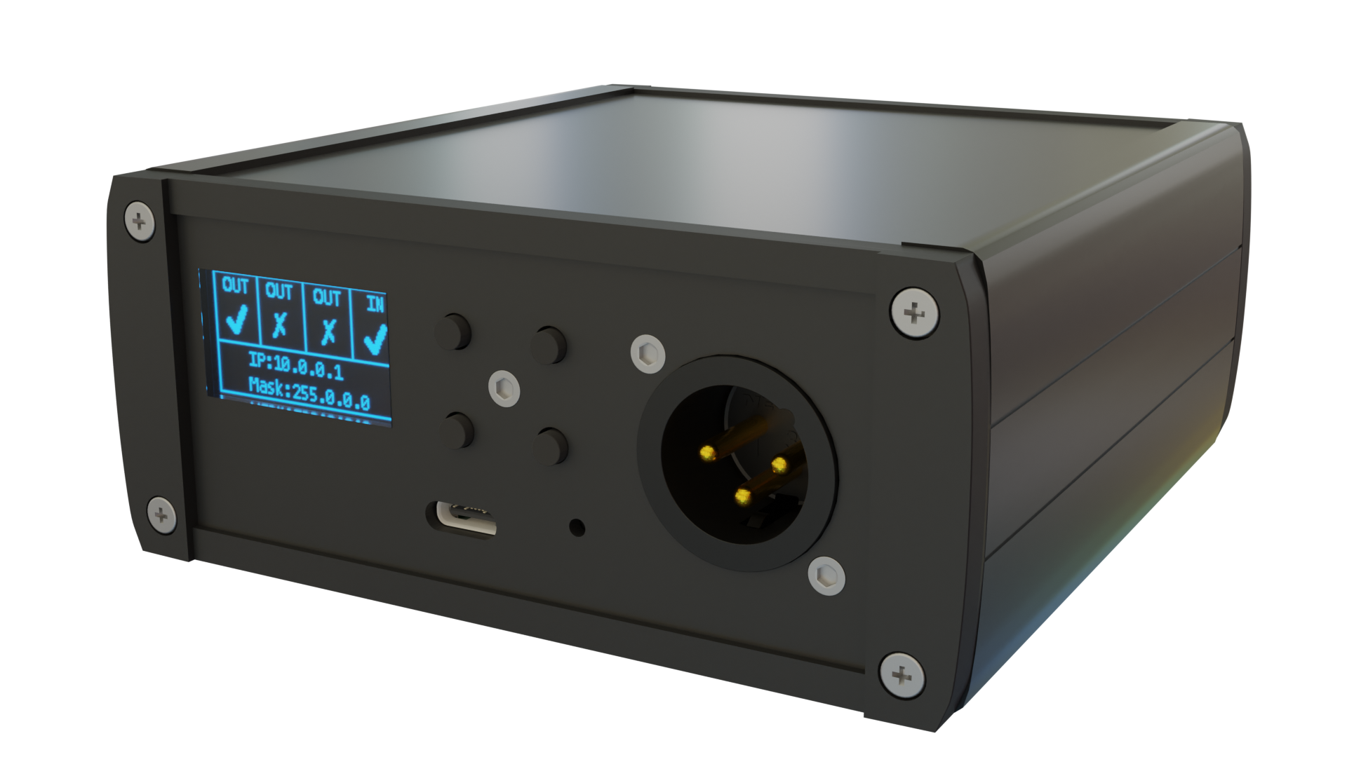
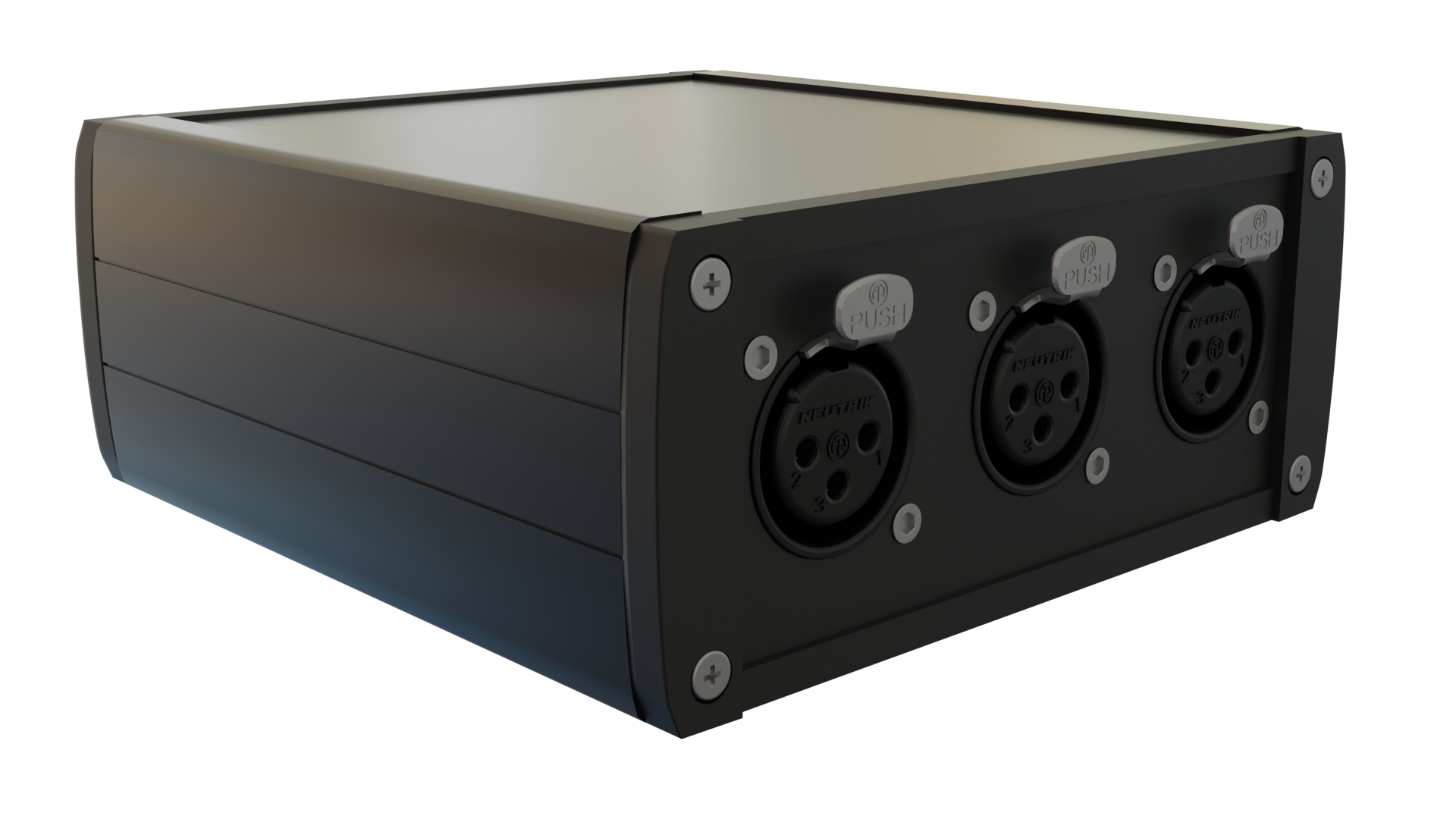
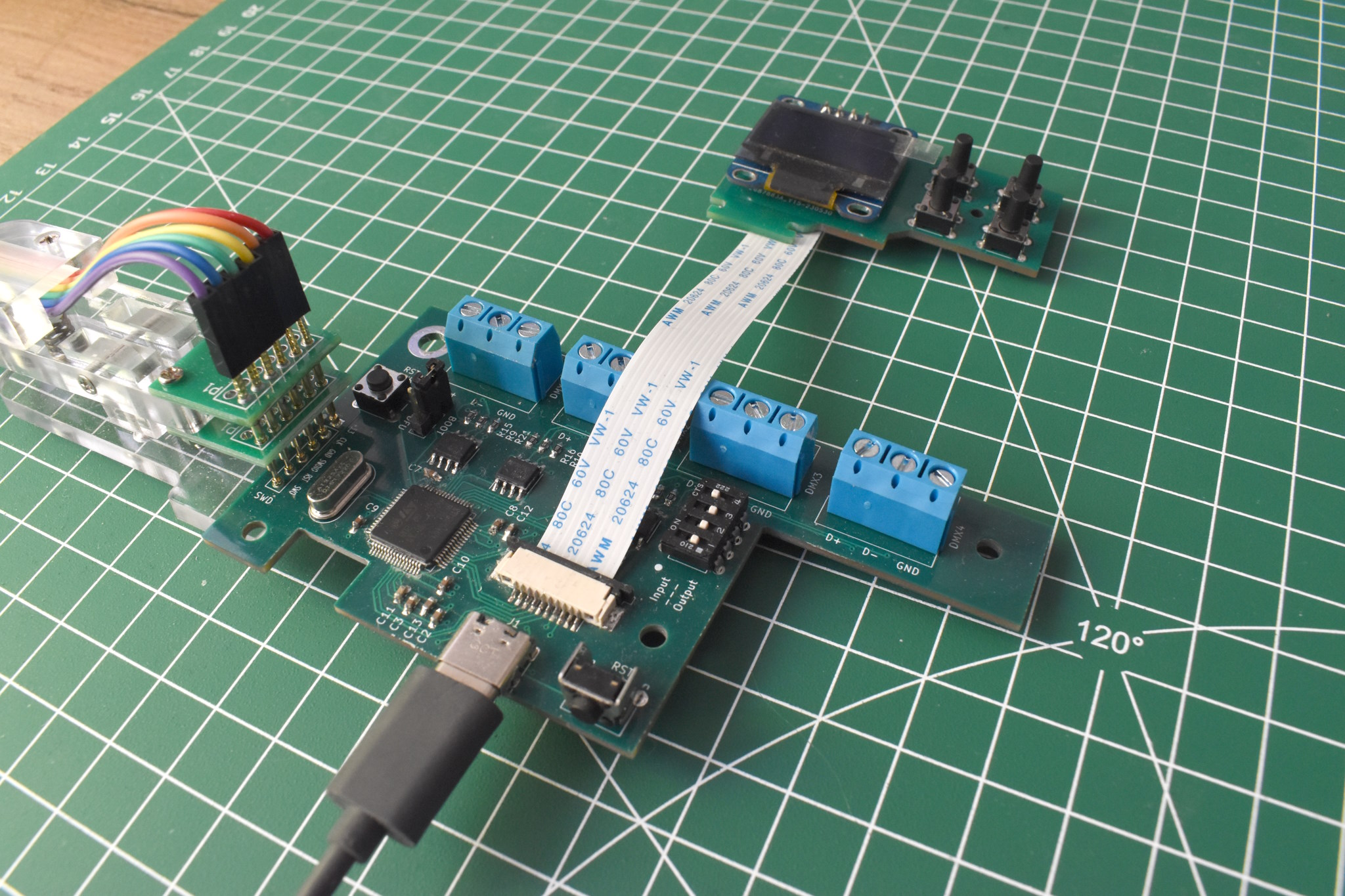
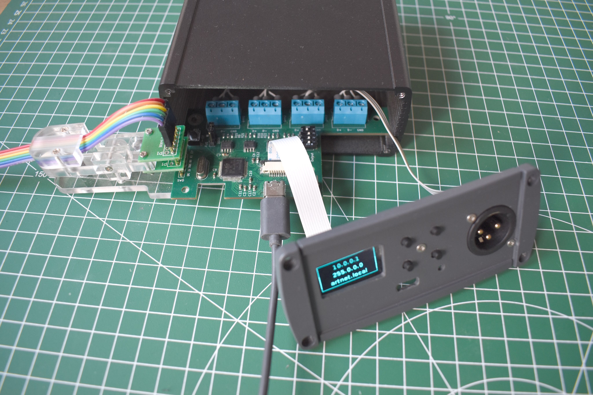
The project uses an STM32G484RE, but should work with any STM32G4xxRE variant. The ports are controlled by a MAX3440E each, which will provide some ESD protection in addition to the TVS-Diodes. The device will draw around ~150mA, which is easily delivered by USB2.0 ports. Galvanic isolation was omitted because it needs too much space and because it is not recommended for the transmitting ports of DMX-Devices anyway (although it is recommended for receiving ports, but not mandatory).
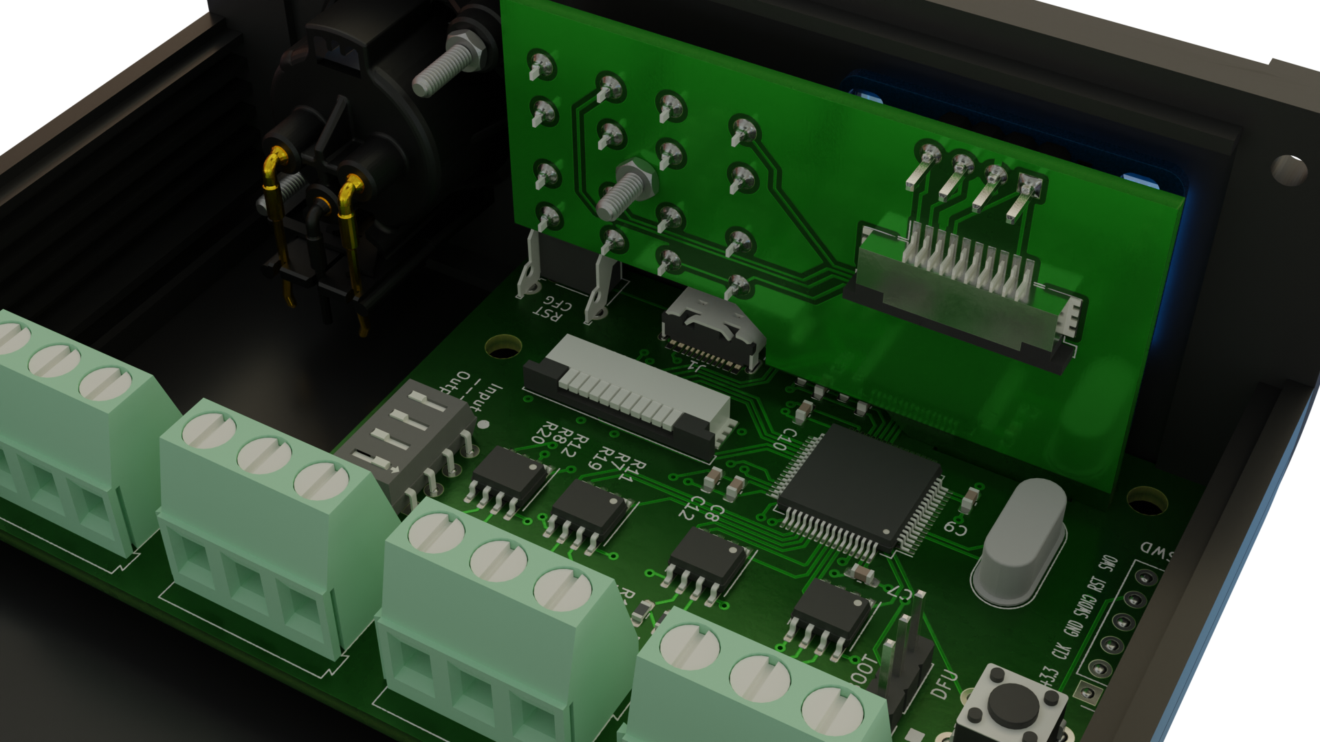
The PCB is designed as a four layer board, as with this small size the price was acceptable. The pcb was designed with a TEKAL 31.29-case from TEKO in mind, but any case with at least 100x100mm will work. placing three ports at the rear and one port beside the usb port at the front of the case. The display module is completely optional and is designed to slot into the mainboard and is secured with an additional screw from the front. It is then connected using a 10-pin ribbon cable.
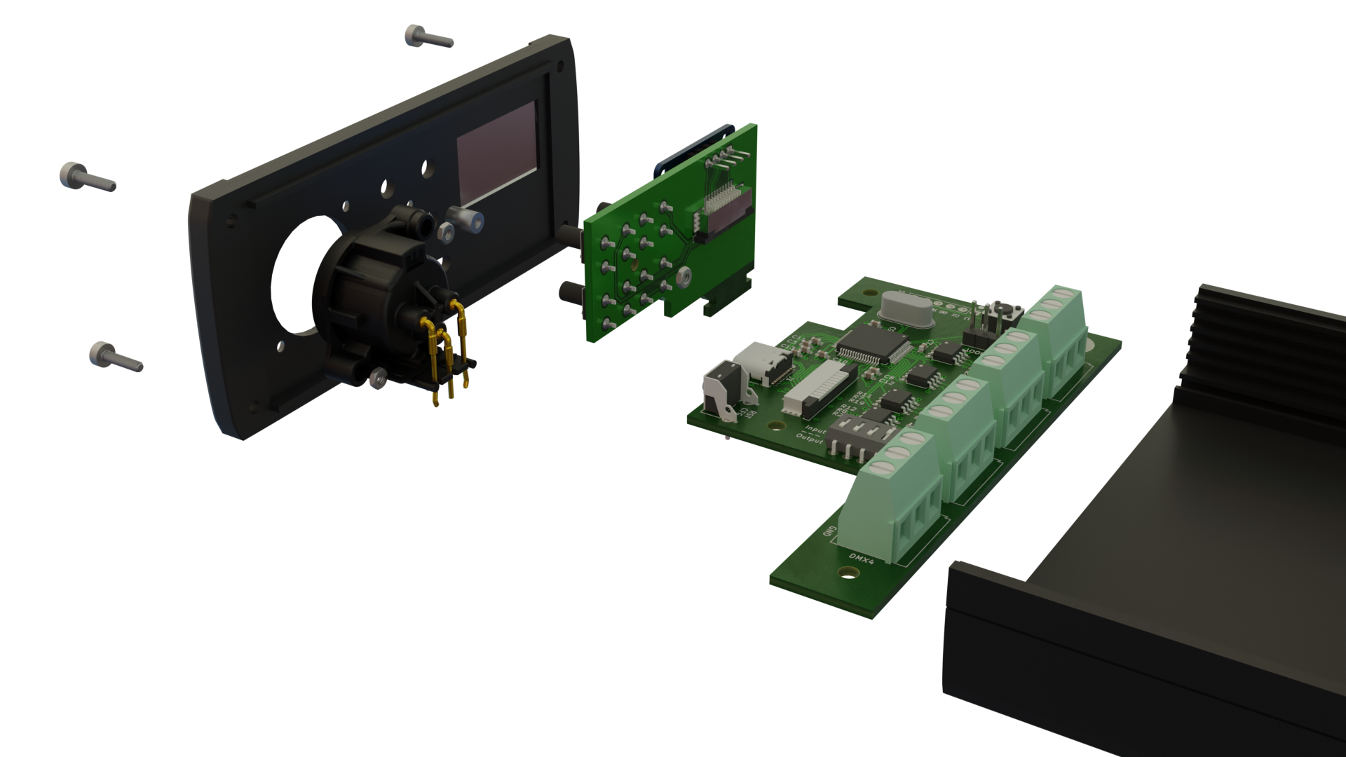
The total cost for this device is currently aproximately 90€. Assembly takes around 6 hours, including soldering the boards, CNC the covers and soldering / crimping the connectors. You can save money by printing your own case (25€), finding a cheaper STM32G4xxRE variant at your local dealer (11€), finding cheaper XLR connectors (5€) and skipping on the display module (5€).
| Amount | Type | Value | Footprint |
|---|---|---|---|
| 4 | Capacitor | 1μF | 0603 |
| 7 | Capacitor | 100nF | 0603 |
| 2 | Capacitor | 20pF | 0603 |
| 1 | Capacitor | 10nF | 0603 |
| 1 | Capacitor | 4.7μF | 0603 |
| 8 | TVS Diode | SMA | |
| 1 | USB-C Receptacle | ||
| 1 | FFC Connector | 1x10, Pitch 1mm | |
| 4 | Terminal Block | 1x3, Pitch 2.54mm | |
| 1 | Pin Header | 1x3, Pitch 2.54mm | |
| 1 | Jumper | 1x2, Pitch 2.54mm | |
| 2 | Resistor | 5K1 | 0603 |
| 1 | Resistor | 4K7 | 0603 |
| 4 | Resistor | 130 | 0603 |
| 8 | Resistor | 560 | 0603 |
| 1 | Switch | Through Hole, Height 6mm | |
| 1 | Switch | Through Hole, Angled, Height 6mm | |
| 1 | DIP-Switch | Through Hole, 2x4, Pitch 2.54mm | |
| 1 | ESD Protection | ESDALD05UD4 | SOT23-6 |
| 1 | Linear Regulator | AP2112K-3.3 | SOT23-5 |
| 4 | Transceiver | MAX3440E | SOIC-8 |
| 1 | Crystal | 25MHz | HC49 |
| 1 | μC | STM32G484RE | LQFP64 |
| Amount | Type | Footprint |
|---|---|---|
| 1 | OLED-Display | 0.96" with I²C and SSD1306 compatible driver |
| 1 | FFC Connector | 1x10, Pitch 1mm |
| 2 | Resistor | 4K7 |
| 4 | Switch | Through Hole, Height 10mm |
| 1 | FFC Cable | 1x10, Pitch 1mm, Length ~100mm, Type B (opposing-side contacts) |
| Amount | Type | Specs |
|---|---|---|
| 1 | Case | TEKO TEKAL 31.29, or any case that takes Eurocard-sized PCBs (100x100mm) |
| 4 | XLR Connector | An individual mix of Female and Male XLR 3- and 5-Pin connectors, depending on your needs |
| 9 | Screws | M2, Length 15mm, Countersink |
| 9 | Nuts | M2 |
| 1 | Acrylic Window | 15mm x 25mm |
| 1 | Spacer | M2, Length 6mm |
| 1 | Mainboard PCB | |
| 1 | Display PCB |
Here are two lists on digikey that include all necessary components, except for the mechanical parts and the oled-display. It does contain four XLR-Connectors though.
The firmware is completely custom, only based on CMSIS (no HAL) and supports the important parts of the ArtNET protocol. Which port is an input and which an output can be set using the dip switches, but later be overwritten using either ArtNET commands, the WebUI or the display menu. The device also has a reset button to reset the configuration for when things go completely wrong. If the device is completely bricked it can be put into bootloader mode using a jumper on the mainboard.
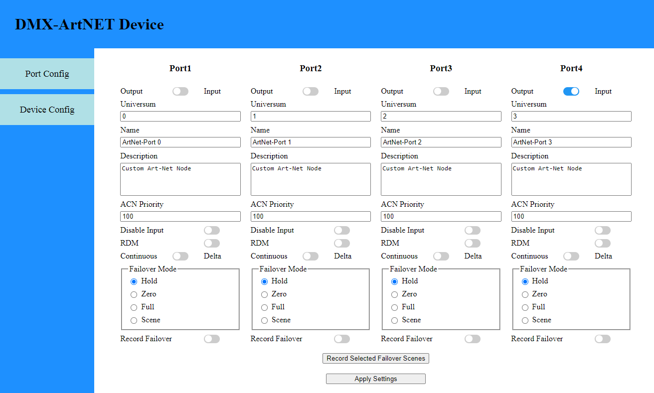
The device supports mDNS and is always reachable using artnet.local in addition to its ip-address. The WebUI allows configuring each individual port with all the settings that ArtNET-Commands also support. You can also change the ip-configuration of the device and its internal minimal DHCP-Server, as well as clearing all settings, rebooting the device and switching the device into DFU/Bootloader mode to flash a new firmware.
| Qty | Value | Footprint | References |
|---|---|---|---|
| 8 | 560 | Resistor_SMD:R_0603_1608Metric_Pad0.98x0.95mm_HandSolder | R11, R12, R15, R16, R19, R20, R21, R22 |
| 8 | D_TVS | Diode_SMD:D_SMA_Handsoldering | D5, D6, D7, D8, D9, D10, D11, D12 |
| 7 | 100nF | Capacitor_SMD:C_0603_1608Metric_Pad1.08x0.95mm_HandSolder | C3, C4, C7, C8, C9, C10, C14 |
| 4 | 130 | Resistor_SMD:R_0603_1608Metric_Pad0.98x0.95mm_HandSolder | R7, R8, R9, R10 |
| 4 | DMX | TerminalBlock:TerminalBlock_Altech_AK300-3_P5.00mm | J3, J4, J5, J6 |
| 4 | MAX3440E | Package_SO:SOIC-8_3.9x4.9mm_P1.27mm | U5, U6, U7, U8 |
| 2 | 1uF | Capacitor_SMD:C_0603_1608Metric_Pad1.08x0.95mm_HandSolder | C2, C13 |
| 2 | 1μF | Capacitor_SMD:C_0603_1608Metric_Pad1.08x0.95mm_HandSolder | C1, C15 |
| 2 | 20pF | Capacitor_SMD:C_0603_1608Metric_Pad1.08x0.95mm_HandSolder | C5, C6 |
| 2 | 5K1 | Resistor_SMD:R_0603_1608Metric_Pad0.98x0.95mm_HandSolder | R3, R4 |
| 1 | 10nF | Capacitor_SMD:C_0603_1608Metric_Pad1.08x0.95mm_HandSolder | C11 |
| 1 | 25MHz | Crystal:Crystal_HC18-U_Vertical | Y1 |
| 1 | 4.7uF | Capacitor_SMD:C_0603_1608Metric_Pad1.08x0.95mm_HandSolder | C12 |
| 1 | 4K7 | Resistor_SMD:R_0603_1608Metric_Pad0.98x0.95mm_HandSolder | R5 |
| 1 | AP2112K-3.3 | Package_TO_SOT_SMD:SOT-23-5_HandSoldering | U2 |
| 1 | Conn_01x01 | MountingHole:MountingHole_4.3mm_M4_DIN965_Pad | J9 |
| 1 | ESDALD05UD4 | Package_TO_SOT_SMD:SOT-23-6_Handsoldering | U1 |
| 1 | Jumper_3_Bridged12 | Connector_PinHeader_2.54mm:PinHeader_1x03_P2.54mm_Vertical | JP1 |
| 1 | STM32G474RET | Package_QFP:LQFP-64_10x10mm_P0.5mm | U3 |
| 1 | SWD | Connector_PinHeader_2.54mm:PinHeader_1x06_P2.54mm_Vertical | J8 |
| 1 | SW_DIP_x04 | Package_DIP:DIP-8_W7.62mm | SW2 |
| 1 | SW_Push | Button_Switch_THT:SW_PUSH_6mm | SW1 |
| 1 | SW_Push | Button_Switch_THT:SW_Tactile_SPST_Angled_PTS645Vx39-2LFS | SW3 |
| 1 | Subboard | Connector_FFC-FPC:TE_1-84953-0_1x10-1MP_P1.0mm_Horizontal | J2 |
| 1 | USB_C_Receptacle_USB2.0 | Connector_USB:USB_C_Receptacle_HRO_TYPE-C-31-M-12 | J1 |
The 58 most common of 61 parts.
It measures 100 × 52.3 mm and has 4 copper layers, 1.61 mm thick.
61 parts, built around the STM32G474RET6, MAX3440ESA, AP2112K-3.3 and ESDALD05UD4X. The full list of its parts is on this page, with links to each part's symbol and footprint where PCBKit's library has them.
From the CShark/Lumen-ArtNode repository on GitHub, at the commit this page was made from: the board is hardware/schematic/Main/DMX.kicad_pcb and its schematic hardware/schematic/Main/DMX.kicad_sch. PCBKit opens the board in the browser, with nothing to install.
Its repository states no licence, so its author keeps all rights: ask CShark before reusing the design.


K0iNguyen/LightProcessor
PCB code and design for Optical chemical potential mapping research at Zeng Lab, Purdue University.

etiennechlt/electronic-chess
Générée par tools/boardgen (module power). 100 x 60 mm, 2 couches, plan de masse en face arrière. Elle gère trois cellules plates 1S 5 Ah.


NicholasKorth/BedCooler
A dual-zone heating and cooling controller for a bed: a 6-layer KiCad board with an STM32G474 real-time controller and a Raspberry Pi Compute Module 5 host.
cracked-machine/FunctionGeneratorCortexM4_HW
A function generator powered by ARM Cortex M4