2 layers109.2 × 91.4 mm
FunctionGeneratorCortexM4
cracked-machine/FunctionGeneratorCortexM4_HW
A function generator powered by ARM Cortex M4
88 parts2MIT
 cracked-machine/FunctionGeneratorCortexM4_HW2
A function generator powered by ARM Cortex M4
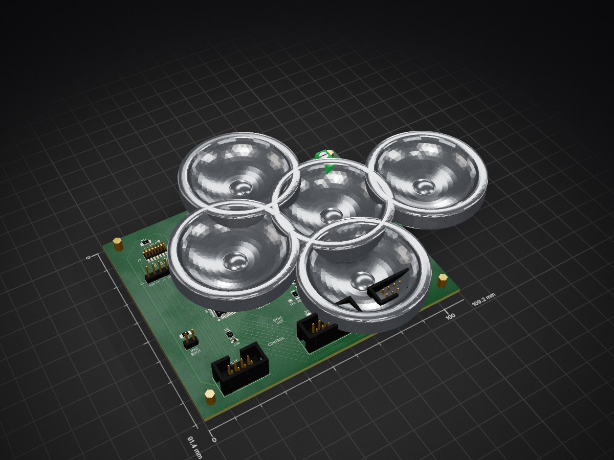
FunctionGeneratorCortexM4 is an open-source printed circuit board by cracked-machine, from the cracked-machine/FunctionGeneratorCortexM4_HW repository on GitHub, published under the MIT licence. It is a 2-layer board of 109.2 × 91.4 mm with 119 parts on 107 nets, routed with 765 tracks and 103 vias.
It is built around the STM32G474RET6, TL072 and TPS60400DBV, with the LM1117-5.0, LP3992-33B5F and TS5A3357DCU among its other parts. Its parts include 41 capacitors, 23 resistors, 14 ICs, 6 diodes and 6 connectors. It belongs with the STM32 boards of this library.


A function generator powered by STM32 G4.
Required Kicad Hardware library: https://github.com/cracked-machine/KicadLibrary
For details of the MCU configuration and firmware refer to FunctionGeneratorCortexM4_SW
Note, RevB was the final design. RevC was not built and is an untested future proposal.
Input signals can be used as a trigger, capturing on voltage level or edge detection.
DAC1 synthesises the main output signal waveform and sends it to a voltage gain amplifier (LTC6910-3). The signal is then mixed with the DC offset signal from DAC2. The signal is then passes through a lowpass filter to remove any high frequency noise.
DAC2 is a DC signal 0-3.3V. This is sent to a buffer and inverting buffer. Either output is selected using the MCU-controlled SPDT switch IC (TS12A12511DCNR). This applies a software configurable DC offset between +3.3V and -3.3V to the main output signal.
DAC3 is an output signal synchronised to DAC1 to be used for triggering purposes.

The display, controls and i/o connectors are connected via daughter boards to the main board via ribbon cable. An example of the display daughter board and its ribbon cable can be seen in the video below:
https://www.instagram.com/p/CA5NSdBhmBY/?utm_source=ig_web_copy_link
| Component | Type | Current |
|---|---|---|
| STM32G4 | MCU | 42mA (max) |
| TL972 | OPAMP | 3.2mA (per amplifier) |
| LTC6910-3 | PGA | 4.9mA |
| TS12A12511 | SPDT | 1uA |
| 74LVC1G3157 | SPDT | 35uA |
| LCD TFT | display | 60mA |
| Total | 120mA |
The 9V input is regulated down to 3.3V and 5V for the MCU and LCD display.
Dual supply for the VGA and opamps are provided using multiple TPS60400 charge pumps. TPS60400 are rated at 60mA output but in testing was found to be less. Therefore, multiple TPS60400 were required to provide "point-of-load" regulation.
Additional filtering is provided at the MCU supply pins with L1 and L2 ferrite beads and C1-C12 bypass capacitors.
A midpoint reference 2.5V voltage is provided to the LTC6910-3 VGA using a TL431DBZ precision programmable reference.
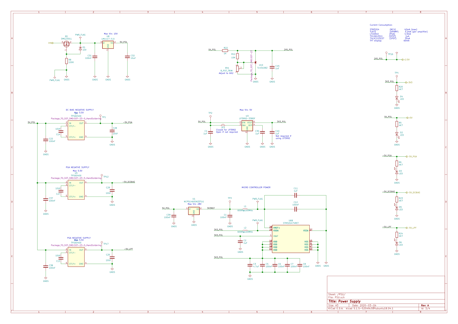
The power supply limits the output to 9Vp-p. The output swing of the VGA limits this further.
The VGA output current is limited to ~25mA. This is also limited by the power supply.
Due to the settling time of the VGA, smooth sweeps between output amplitude levels using this IC was not possible. As such, the output is fixed to the maximum VGA level. Output amplitude control was handled by the firmware instead.
See LTC6910-3 datasheet for more information.
| Qty | Value | Footprint | References |
|---|---|---|---|
| 17 | 100nF | Capacitor_SMD:C_1206_3216Metric_Pad1.42x1.75mm_HandSolder | C1, C5, C6, C7, C12, C16, C21, C22, C31, C33, C34, C35, C36, C37, C38, C39 +1 |
| 15 | TestPoint | TestPoint:TestPoint_Pad_1.0x1.0mm | TP1, TP2, TP3, TP4, TP5, TP6, TP7, TP8, TP9, TP10, TP11, TP12, TP13, TP16, TP17 |
| 9 | 1K | Resistor_SMD:R_1206_3216Metric_Pad1.42x1.75mm_HandSolder | R9, R10, R14, R15, R16, R17, R18, R19, R22 |
| 7 | 1nF | Capacitor_SMD:C_1206_3216Metric_Pad1.42x1.75mm_HandSolder | C15, C17, C18, C19, C20, C23, C24 |
| 6 | 10Uf | Capacitor_SMD:C_1206_3216Metric_Pad1.42x1.75mm_HandSolder | C13, C14, C25, C27, C28, C29 |
| 6 | 1uF | Capacitor_SMD:C_1206_3216Metric_Pad1.42x1.75mm_HandSolder | C2, C4, C10, C11, C30, C41 |
| 5 | 4K7 | Resistor_SMD:R_1206_3216Metric_Pad1.42x1.75mm_HandSolder | R5, R6, R20, R23, R24 |
| 5 | LED | LED_SMD:LED_1206_3216Metric_Pad1.42x1.75mm_HandSolder | D2, D3, D4, D5, D6 |
| 4 | 10K | Resistor_SMD:R_1206_3216Metric_Pad1.42x1.75mm_HandSolder | R2, R3, R7, R12 |
| 3 | Jumper_NO_Small | Jumper:SolderJumper-2_P1.3mm_Open_Pad1.0x1.5mm | JP2, JP4, JP15 |
| 3 | TPS60400 | Package_TO_SOT_SMD:SOT-23-5_HandSoldering | U4, U5, U14 |
| 2 | 10uF | Capacitor_SMD:CP_Elec_4x5.7 | C9, C26 |
| 2 | 50R | Resistor_SMD:R_1206_3216Metric_Pad1.42x1.75mm_HandSolder | R4, R21 |
| 2 | 600R@100MHz | Inductor_SMD:L_1206_3216Metric_Pad1.42x1.75mm_HandSolder | L1, L2 |
| 2 | Jumper_NC_Small | Jumper:SolderJumper-2_P1.3mm_Bridged_Pad1.0x1.5mm | JP1, JP3 |
| 2 | TL072 | Package_SO:SOIC-8_3.9x4.9mm_P1.27mm | U12, U13 |
| 1 | 100K | Resistor_SMD:R_1206_3216Metric_Pad1.42x1.75mm_HandSolder | R8 |
| 1 | 100R | Resistor_SMD:R_1206_3216Metric_Pad1.42x1.75mm_HandSolder | R11 |
| 1 | 100nF | Capacitor_SMD:C_0603_1608Metric_Pad1.05x0.95mm_HandSolder | C40 |
| 1 | 10V | Diode_SMD:D_SOD-123F | D1 |
| 1 | 10uF | Capacitor_SMD:C_1206_3216Metric_Pad1.42x1.75mm_HandSolder | C32 |
| 1 | 4.7uF | Capacitor_SMD:C_1206_3216Metric_Pad1.42x1.75mm_HandSolder | C3 |
| 1 | 560R | Resistor_SMD:R_1206_3216Metric_Pad1.42x1.75mm_HandSolder | R1 |
| 1 | Conn_01x06 | Connector_PinHeader_2.54mm:PinHeader_1x06_P2.54mm_Vertical | J4 |
| 1 | Conn_02x04_Odd_Even | Connector_IDC:IDC-Header_2x04_P2.54mm_Vertical | J6 |
| 1 | Conn_02x05_Odd_Even | Connector_IDC:IDC-Header_2x05_P2.54mm_Vertical | J1 |
| 1 | Conn_02x06_Odd_Even | Connector_IDC:IDC-Header_2x06_P2.54mm_Vertical | J3 |
| 1 | Conn_02x07_Odd_Even | Connector_PinHeader_1.27mm:PinHeader_2x07_P1.27mm_Vertical_SMD | J7 |
| 1 | DMG2301L | Package_TO_SOT_SMD:SOT-23 | Q1 |
| 1 | Jumper_NC_Small | Connector_PinHeader_2.54mm:PinHeader_1x02_P2.54mm_Vertical | JP10 |
| 1 | LM1117-5.0 | Package_TO_SOT_SMD:SOT-223-3_TabPin2 | U8 |
| 1 | LP3992-33B5F | Package_TO_SOT_SMD:TSOT-23-5 | U3 |
| 1 | LTC6910 | Package_TO_SOT_SMD:TSOT-23-8 | U11 |
| 1 | MCP601-xOT | Package_TO_SOT_SMD:SOT-23-5 | U7 |
| 1 | NCP51460SN33T1G | Package_TO_SOT_SMD:SOT-23 | U1 |
| 1 | R_POT_TRIM | Potentiometer_SMD:Potentiometer_Bourns_3314J_Vertical | RV1 |
| 1 | STM32G474RET | Package_QFP:LQFP-64_10x10mm_P0.5mm | U6 |
| 1 | Screw_Terminal_01x02 | TerminalBlock:TerminalBlock_bornier-2_P5.08mm | J2 |
| 1 | TL431DBZ | Package_TO_SOT_SMD:SOT-23 | U10 |
| 1 | TS12A12511DCNR | Package_TO_SOT_SMD:SOT-23-8_Handsoldering | U9 |
| 1 | TS5A3357 | Package_SO:VSSOP-8_2.4x2.1mm_P0.5mm | U2 |
The 115 most common of 119 parts.
It measures 109.2 × 91.4 mm and has 2 copper layers, 1.6 mm thick.
119 parts, built around the STM32G474RET6, TL072, TPS60400DBV and LM1117-5.0. The full list of its parts is on this page, with links to each part's symbol and footprint where PCBKit's library has them.
From the cracked-machine/FunctionGeneratorCortexM4_HW repository on GitHub, at the commit this page was made from: the board is HW/MainBoard/RevB/FunctionGeneratorCortexM4/FunctionGeneratorCortexM4.kicad_pcb. PCBKit opens the board in the browser, with nothing to install.
Its repository publishes it under the MIT licence: you may reuse it on that licence's terms (keep the author's notice, and for a copyleft licence share your changes alike).
cracked-machine/FunctionGeneratorCortexM4_HW
A function generator powered by ARM Cortex M4

cracked-machine/FunctionGeneratorCortexM4_HW
A function generator powered by ARM Cortex M4

cracked-machine/FunctionGeneratorCortexM4_HW
A function generator powered by ARM Cortex M4

cracked-machine/FunctionGeneratorCortexM4_HW
A function generator powered by ARM Cortex M4

cracked-machine/FunctionGeneratorCortexM4_HW
A function generator powered by ARM Cortex M4

cracked-machine/FunctionGeneratorCortexM4_HW
A function generator powered by ARM Cortex M4

cracked-machine/FunctionGeneratorCortexM4_HW
A function generator powered by ARM Cortex M4


Rivercraft911/R-01_Raster_Laser_Projector
Red, blue and green lasers combine through two dichroc mirrors and bounce off a spinning polygon mirror, which each mirror facet makes one scanline.

jlab-sensing/ENTS-node-hardware
Schematics and design for soil MFC voltage and current sensing

Motokichirou/gamma-spectrometer
NaI(Tl) gamma spectrometer: STM32G474 + R1307 PMT + 4-board stack, KiCad schematics, LTspice simulations


TobiasNetzer/nanoLogger
Here is a simplified block diagram of the data logger. To measure the current of a device, the data logger is simply connected in series between the voltage source and the DUT/load.