2 layers57.3 × 92.1 mm
Glitchifier9000
inconspicuous-username/Glitchifier9000
Check out the schematics in this repo for more information!
29 parts13
 CreateRemoteThread/glitcher2
glitcher
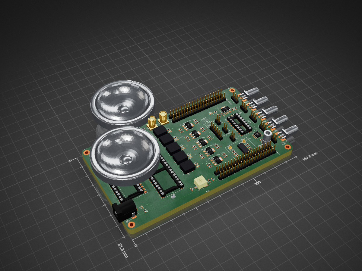
Glitcher is an open-source printed circuit board by CreateRemoteThread, from the CreateRemoteThread/glitcher repository on GitHub. It is a 6-layer board of 140.8 × 81.3 mm with 101 parts on 125 nets, routed with 738 tracks and 29 vias.
It is built around the CMOD A7-35T, SC0915 and IRF7807ZPBF, with the MAX4619CPE+ among its other parts. Its parts include 31 capacitors, 10 ICs, 7 diodes, 7 connectors and 5 switches.


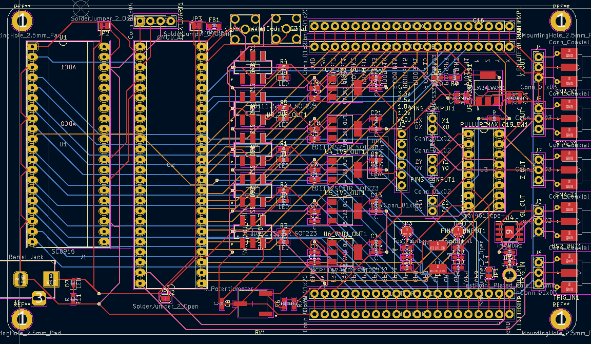
Glitcher is a homebrew fault injection system, built around a Pi Pico and CMOD A7, with a MAX4619 and an irf7807 providing multiplexer and crowbar mosfet style glitching respectively. Generous GPIO (FPGA + Pi Pico) + SMA outputs are available.
This project is heavily inspired by the ChipWhisperer set of products.
The Pi Pico is the simplest method of using this. Using a micro USB cable, access the MicroPython interface and use the glitcher library to control the FPGA's default firmware:
import glitcher

g = glitcher.Glitcher()
g.enablemux(True)                # enable max4619. crowbar always "on"
g.setmask(glitcher.SELECT_MOSFET)         # select mosfet for glitching
g.muxout(glitcher.SELECT_MUXA)            # switch x_out to x1
g.muxout(glitcher.SELECT_NONE)            # switch x_out to x0
g.rnr(delay=5,width=5)           # write delay/width, glitch output according to setmask
The Pi Pico uses only a serial port to talk to the FPGA at 115200bps, so you can swap it for some other uC / make a shield / whatever. Just replace self.u1 with a pyserial output if you want to use a control PC (enablemux is the only thing requiring the pi pico, just hardwire it idk).
Probably don't use g.muxout(0xF) - but do whatever you want.
| Qty | Value | Footprint | References |
|---|---|---|---|
| 31 | C | Capacitor_SMD:C_0603_1608Metric_Pad1.08x0.95mm_HandSolder | C1, C2, C10, C11, C12, C13, C14, C15, C16, C17, C18, C19, C20, C21, C22, C23 +15 |
| 9 | R | Resistor_SMD:R_0603_1608Metric_Pad0.98x0.95mm_HandSolder | PULLUP_MAX4619_EN1, R1, R2, R3, R4, R5, R6, R7, R8 |
| 6 | LED | LED_SMD:LED_0603_1608Metric_Pad1.05x0.95mm_HandSolder | D1, D2, D3, D4, D5, D6 |
| 5 | Conn_01x03 | Connector_PinHeader_2.54mm:PinHeader_1x03_P2.54mm_Vertical | J3, J4, J5, J6, J7 |
| 5 | Conn_Coaxial | Connector_Coaxial:SMA_Molex_73251-2120_EdgeMount_Horizontal | HS2_OUT1, SMA_X1, SMA_Y1, SMA_Z1, TRIG_IN1 |
| 5 | SW_DPDT_x2 | all_lib:JS202011SCQN | SW1_1V8_OUT1, SW2_1V2_OUT1, SW3_VADJ_OUT1, SW4_3V3_OUT1, SW5_2V5_OUT1 |
| 4 | Conn_01x20 | Connector_PinHeader_2.54mm:PinHeader_1x20_P2.54mm_Vertical | J_LEFTEXP_OUTER1, J_LEFTEXP1, J_RIGHTEXP_OUTER1, J_RIGHTEXP1 |
| 3 | Conn_01x02 | Connector_PinHeader_2.54mm:PinHeader_1x02_P2.54mm_Vertical | PINS_X_INPUT1, PINS_Y_INPUT1, PINS_Z_INPUT1 |
| 2 | Conn_Coaxial | all_lib:RF2-04A-T-00-50-G | J_HVPULSE1, J_TRIG2 |
| 2 | LD1117S33TR_SOT223 | Package_TO_SOT_SMD:SOT-223-3_TabPin2 | U7_3V3_OUT1, U9_3V3ALWAYS1 |
| 2 | SolderJumper_2_Open | Jumper:SolderJumper-2_P1.3mm_Open_RoundedPad1.0x1.5mm | JP1, JP4 |
| 2 | SolderJumper_2_Open | Jumper:SolderJumper-2_P1.3mm_Open_Pad1.0x1.5mm | JP2, JP3 |
| 2 | TestPoint | TestPoint:TestPoint_Pad_D2.5mm | TP3, TP4 |
| 1 | 10K R | Resistor_SMD:R_0603_1608Metric_Pad0.98x0.95mm_HandSolder | R10 |
| 1 | 1R | Resistor_SMD:R_0603_1608Metric_Pad0.98x0.95mm_HandSolder | R9 |
| 1 | Barrel_Jack | Connector_BarrelJack:BarrelJack_Horizontal | J1 |
| 1 | CMOD_A7 | Package_DIP:DIP-48_W15.24mm_Socket_LongPads | U2 |
| 1 | Conn_01x04 | Connector_PinHeader_2.54mm:PinHeader_1x04_P2.54mm_Vertical | J_EXT_UART1 |
| 1 | Conn_01x06 | Connector_PinHeader_2.54mm:PinHeader_1x06_P2.54mm_Vertical | J2 |
| 1 | FerriteBead | Inductor_SMD:L_0805_2012Metric_Pad1.05x1.20mm_HandSolder | FB1 |
| 1 | INDUCTOR | all_lib:inductor_2727_wurth | L1 |
| 1 | LD1117S12TR_SOT223 | Package_TO_SOT_SMD:SOT-223-3_TabPin2 | U5_1V2_OUT1 |
| 1 | LD1117S18TR_SOT223 | Package_TO_SOT_SMD:SOT-223-3_TabPin2 | U4_1V8_OUT1 |
| 1 | LD1117S25TR_SOT223 | Package_TO_SOT_SMD:SOT-223-3_TabPin2 | U8_2V5_OUT1 |
| 1 | LED | LED_SMD:LED_0603_1608Metric | D7 |
| 1 | NCP1117-ADJ_SOT223 | Package_TO_SOT_SMD:SOT-223-3_TabPin2 | U6_VADJ_OUT1 |
| 1 | R | Resistor_SMD:R_0603_1608Metric | R11 |
| 1 | R_Potentiometer | all_lib:TRIM_3361P-1-501GLF | RV1 |
| 1 | SC0915 | all_lib:rpi_socket_fixed | U1 |
| 1 | irf7807z | Package_SO:SOIC-8-1EP_3.9x4.9mm_P1.27mm_EP2.29x3mm | U4 |
| 1 | max4619cpe+ | Package_DIP:DIP-16_W7.62mm_Socket_LongPads | U3 |
The 96 most common of 101 parts.
It measures 140.8 × 81.3 mm and has 6 copper layers, 5.72 mm thick.
101 parts, built around the CMOD A7-35T, SC0915, IRF7807ZPBF and MAX4619CPE+. The full list of its parts is on this page, with links to each part's symbol and footprint where PCBKit's library has them.
From the CreateRemoteThread/glitcher repository on GitHub, at the commit this page was made from: the board is glitcher/glitcher.kicad_pcb and its schematic glitcher/bifrost.kicad_sch. PCBKit opens the board in the browser, with nothing to install.
Its repository states no licence, so its author keeps all rights: ask CreateRemoteThread before reusing the design.
inconspicuous-username/Glitchifier9000
Check out the schematics in this repo for more information!

GMUCERG/fobos
Flexible Open-source workBench fOr Side-channel analysis (FOBOS)


OipRDDinoSaric/Controlling-analogue-switches-on-a-PIC-microcontroller
Designing and soldering a PCB. Programming a PIC microcontroller using MP LAB X-IDE.


MacMannes/XVA1-User-Interface
A hardware user interface for the XVA1 virtual analog synthesizer, inspired by the Hydrasynth's layout. The XVA1 (and its FM sibling the XFM2) is built on an Artix-7 FPGA but has no built-in UI — this project adds one.

IIP-Group/polymap
Repository for the PolyMap Hardware and PolyMap Studio VST Plugin (prototype version).