

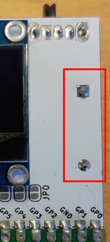
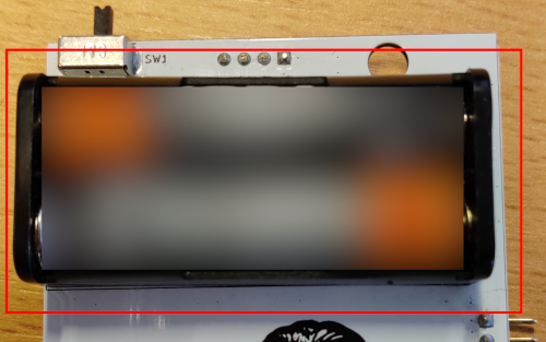
6 layers140.8 × 81.3 mm

 inconspicuous-username/Glitchifier900013
Check out the schematics in this repo for more information!
Glitchifier9000 is an open-source printed circuit board by inconspicuous-username, from the inconspicuous-username/Glitchifier9000 repository on GitHub. It is a 2-layer board of 57.3 × 92.1 mm with 29 parts on 41 nets, routed with 116 tracks and 83 vias.
It is built around the IRF7807ZPBF and DMG2305UX. Its parts include 3 connectors, 2 capacitors, 2 resistors, 2 ICs and 2 switches. It belongs with the RP2040 boards of this library.

Some howto’s below.
 Figure 1: What is voltage
glitching?
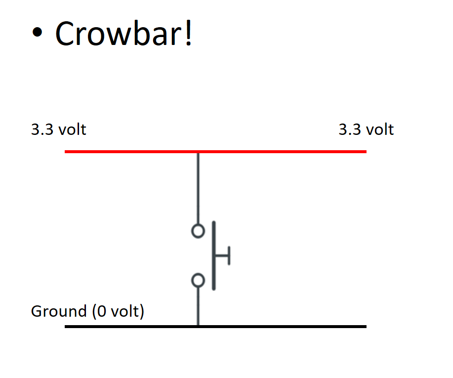 Figure 2: Normal operation
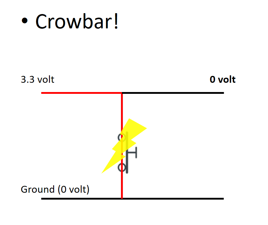 Figure 3: While glitching
Check out the schematics in this repo for more information!
NOTE: The trigger input is currently set to the button for demo purposes, the use a different pin you have to modify this line.
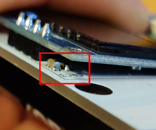
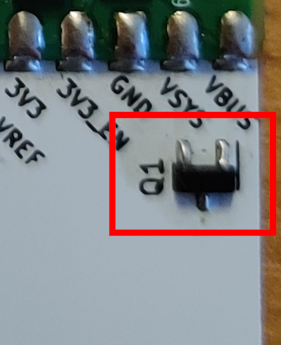
To get minimal badge functionality:
|
|
|
|
|
|
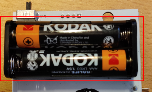
You should now be able to see stuff on the screen, and you can interact over USB / serial.
To control the badge with the button:
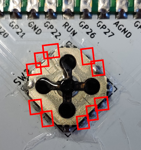
You should now be able to use the botton.
To add GLITCHIFIER9000 functionality:
Ready to glitch!
Ready to talk!

Ready to talk!
Set up PICO for badge
Set up micropython firmware
uf2 file to storage device (download yourself
or located in firmware/upython/rp2-firmware/rp2-pico-latest.uf2)Copy firmware folder to device, for example with
mpytool
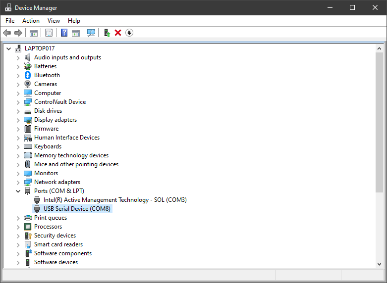
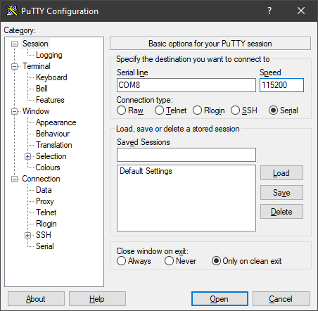
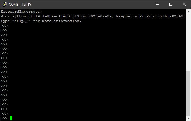
mpytool -p SERIALPORT put firmware/upython/badge/To do stuff over serial, connect with SERIALPORT, baudrate 115200.
To build this document in to various formats:
quarto render README.qmd --to pdf && \
quarto render README.qmd --to html && \
quarto render README.qmd --to docx && \
quarto render README.qmd --to gfm| Qty | Value | Footprint | References |
|---|---|---|---|
| 14 | SolderJumper_2_Bridged | Jumper:SolderJumper-2_P1.3mm_Bridged_RoundedPad1.0x1.5mm | JP0, JP1, JP2, JP3, JP4, JP5, JP6, JP7, JP8, JP9, JP10, JP11, JP12, JP14 |
| 2 | C | Capacitor_SMD:C_0805_2012Metric | C3, C4 |
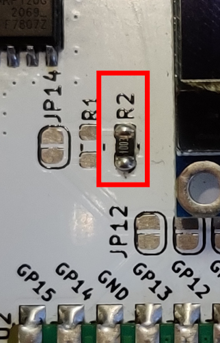
| 1 | 100k | Resistor_SMD:R_0805_2012Metric | R2 |
| 1 | Battery | Battery:BatteryHolder_Keystone_2468_2xAAA | BT1 |
| 1 | Conn_01x02 | Connector_PinHeader_2.54mm:PinHeader_1x02_P2.54mm_Vertical | J2 |
| 1 | Conn_01x04 | Connector_PinHeader_2.54mm:PinHeader_1x08_P2.54mm_Vertical | J3 |
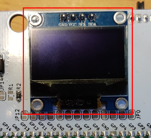
| 1 | Conn_01x04 | Oled_I2C_Display:128x64 | J1 |
| 1 | DMG2305UX | Package_TO_SOT_SMD:SOT-23 | Q1 |
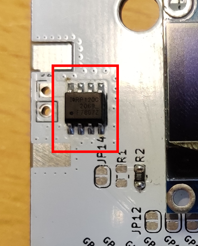
| 1 | IRF7807z | IRF7807:IRF7808z | U1 |
| 1 | Pico | MCU_RaspberryPi_and_Boards:RPi_Pico_SMD_TH | U2 |
| 1 | R | Resistor_SMD:R_0805_2012Metric | R1 |
| 1 | SW_DIP_x05 | 5-way_switch:JS1300AQ_5-way_switch | SW2 |
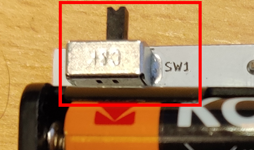
| 1 | SW_SPDT | Button_Switch_THT:SW_CuK_OS102011MA1QN1_SPDT_Angled | SW1 |
| 1 | your_opinion | the_dude:your_opinion | G*** |
The 28 most common of 29 parts.

GMUCERG/fobos
Flexible Open-source workBench fOr Side-channel analysis (FOBOS)

Hack-a-Day/2025-Communicator_Badge
The 2025 Hackaday Supercon RF Communicator Badge


hasenbanck/heteromycin
A 3D printer board using a powerfull STM32 MCU, TMC5160/TMC2160 driver and a Raspberry Pi or compatible SBC


It measures 57.3 × 92.1 mm and has 2 copper layers, 4.69 mm thick.
29 parts, built around the IRF7807ZPBF and DMG2305UX. The full list of its parts is on this page, with links to each part's symbol and footprint where PCBKit's library has them.
From the inconspicuous-username/Glitchifier9000 repository on GitHub, at the commit this page was made from: the board is hardware/Kicad/Glitchifier9000/Glitchifier9000.kicad_pcb and its schematic hardware/Kicad/Glitchifier9000/Glitchifier9000.kicad_sch. PCBKit opens the board in the browser, with nothing to install.
Its repository states no licence, so its author keeps all rights: ask inconspicuous-username before reusing the design.