
4 layers120.6 × 72.4 mm

cheap and terrible voltage glitcher hardware/software
Pmod2 is an open-source printed circuit board by noopwafel, from the noopwafel/iceglitch repository on GitHub. It is a 2-layer board of 52.5 × 44.3 mm with 44 parts on 36 nets, routed with 446 tracks and 37 vias.
It is built around the L272M, MAX4232AKA and MCP4822-E/P, with the THS4631DDA, MAX4619CPE+ and TS5A63157DCK among its other parts. Its parts include 13 capacitors, 9 ICs, 8 resistors, 7 connectors and 3 inductors.


iceGLITCH is a cheap, fun and terrible voltage glitcher!
You can use it to inject faults in the voltage line of targets, making them do weird things.
You can control both the normal and glitch voltage levels, and if you squint and sort of wave your hands a lot, then you can pretend you get ~200ps of resolution for the glitch length (time that the voltage is changed from normal to glitch level). Accuracy, on the other hand, is left as an exercise for the reader..
Many people played with this at the 'Hardware Slackers' assembly at 36C3! We're still recovering and will update the repository once we've gotten a few days of good sleep.
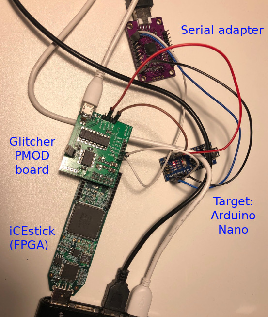
This is what a typical setup looks like:
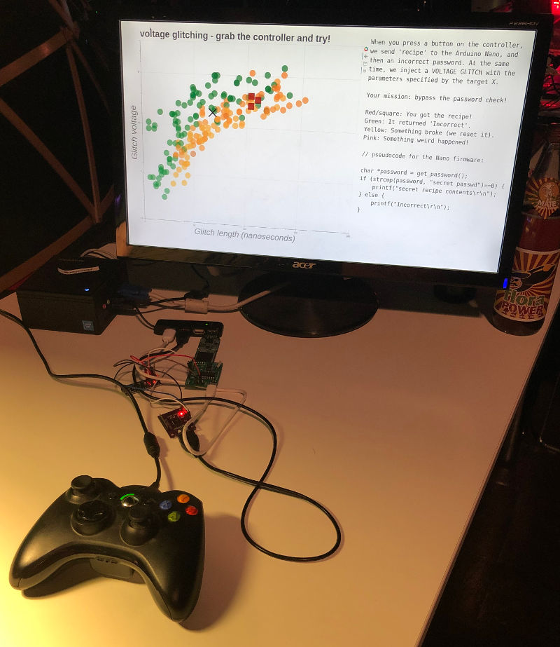
And this is an example of what a real-world attack looks like (from our 36C3 assembly):
You can solder a good-enough (fun!) version of this glitcher using protoboard, but nowadays we use a PCB version (see the 'pcb' directory). You can solder several different combinations of components to get different glitcher designs, some of which make more sense than others; however, we guarantee that all combinations will be both terrible and fun.
You can use it with any ICE40HX FPGA board with a PMOD connector; we're using the cheap (~22eur) 'iCEstick'.
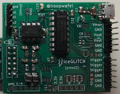
Also it turns out you don't have to solder it nicely, it'll work fine anyway:
The 'TOE' directory contains code for some example targets.
The FPGA code (to be built using the open source yosys/nextpnr toolchain) is in the 'fpga' directory. We can't write verilog, there are no test cases, it is all terrible. We are sorry, our code is bad and we should feel bad. But it works :D
The (python) scripts are in the 'scripts' directory, including scripts to attack the example targets.
We built a horrible, horrible 5eur "oscilloscope" for our 35C3 side channel analysis workshop: the HorrorScope. This glitcher is our attempt to build a similar cheap-and-cheerful workshop platform for voltage glitching.
Some of our friends used it at the HITB CyberWeek in October 2019, and we "released" it at 36C3 in December 2019.
Thanks to everyone who helped inspire or test our hacks, and thanks to @nedos in particular for making us realize we could just use a cheap analog switch rather than overcomplicating things!
| Qty | Value | Footprint | References |
|---|---|---|---|
| 13 | C | Capacitor_SMD:C_0805_2012Metric_Pad1.15x1.40mm_HandSolder | C1, C2, C3, C4, C5, C6, C7, C8, C9, C10, C11, C12, C13 |
| 8 | R | Resistor_SMD:R_0805_2012Metric_Pad1.15x1.40mm_HandSolder | R1, R2, R3, R4, R5, R7, Rld1, Rld2 |
| 4 | 0 | Resistor_SMD:R_0805_2012Metric_Pad1.15x1.40mm_HandSolder | Rfb1, Rfb2, Rfb3, Rfb4 |
| 4 | Conn_01x04 | Connector_PinHeader_2.54mm:PinHeader_1x06_P2.54mm_Vertical | J3, J4, J6, J7 |
| 2 | L | Inductor_SMD:L_1210_3225Metric_Pad1.42x2.65mm_HandSolder | L1, L2 |
| 2 | trigger | Package_TO_SOT_SMD:SOT-23-6 | U5, U6 |
| 1 | AP2210N-4.0 | Package_TO_SOT_SMD:TSOT-23 | U8 |
| 1 | Conn_01x04 | Connector_PinHeader_2.54mm:PinHeader_1x05_P2.54mm_Vertical | J5 |
| 1 | Ferrite_Bead_Small | Inductor_SMD:L_0805_2012Metric_Pad1.15x1.40mm_HandSolder | L3 |
| 1 | L272M | Package_DIP:DIP-8_W7.62mm_LongPads | U1 |
| 1 | MAX4232 | Package_TO_SOT_SMD:SOT-23-8 | U7 |
| 1 | MAX4619 | Package_DIP:DIP-16_W7.62mm_LongPads | U2 |
| 1 | MCP4822 | Package_SO:SOIC-8_3.9x4.9mm_P1.27mm | U3 |
| 1 | PMOD | Connector_PinHeader_2.54mm:PinHeader_2x06_P2.54mm_Vertical | J2 |
| 1 | THS4631DDA | Package_SO:SOIC-8_3.9x4.9mm_P1.27mm | U9 |
| 1 | TS5A63157 | Package_TO_SOT_SMD:SOT-23-6 | U4 |
| 1 | USB_B_Micro | custom:USB_Micro-B_Amphenol_hax | J1 |


OipRDDinoSaric/Controlling-analogue-switches-on-a-PIC-microcontroller
Designing and soldering a PCB. Programming a PIC microcontroller using MP LAB X-IDE.

fossasia/pslab-hardware
PSLab Hardware Design and Schematics https://pslab.io

matthewcieplak/super-sixteen
Code and schematics for the Super Sixteen Eurorack sequencer


strawlab/triggerbox
camera triggering for synchronized multi-camera setups
It measures 52.5 × 44.3 mm and has 2 copper layers, 1.6 mm thick.
44 parts, built around the L272M, MAX4232AKA, MCP4822-E/P and THS4631DDA. The full list of its parts is on this page, with links to each part's symbol and footprint where PCBKit's library has them.
From the noopwafel/iceglitch repository on GitHub, at the commit this page was made from: the board is pcb/pmod2/pmod2.kicad_pcb. PCBKit opens the board in the browser, with nothing to install.
Its repository states no licence, so its author keeps all rights: ask noopwafel before reusing the design.