

2 layers60 × 111.3 mm
Silkscreen pcb
iandchasse/silkscreen-pcb
Silkscreen: open-hardware ESP32-S3 e-paper reader mainboard (KiCad 9). Formerly the de-link hub.
189 parts589CERN-OHL-S-2.0
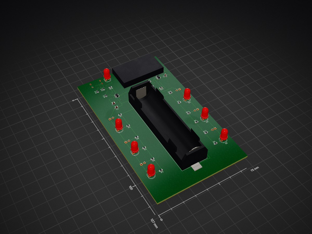
Beacon for Bow (soon stern) for Navigational/Safety purposes when traversing waterways
RPI Beacon is an open-source printed circuit board by computersandrew, from the computersandrew/Modular-Boat-Beacon-Light repository on GitHub. It is a 2-layer board of 75 × 127 mm with 41 parts on 30 nets, routed with 190 tracks and 28 vias.
It is built around the DW01A and FS8205A. Its parts include 18 resistors, 13 diodes, 3 capacitors, 2 ICs and 1 transistor.
A rebuild of the RowKraft Beacon, a small red/green nav light for rowing shells. The original board is from 2012 (RowKraft LLC). I'm redesigning it in KiCad with a few upgrades because I can, (mostly I can't afford 55 dollars):
The board mounts along the boat's centerline inside a sealed, semi-transparent 3D printed tube. Red LEDs are on the front (port side), green on the back (starboard side). Screwing down the end cap presses a lever microswitch, which turns the lights on.
Status: Version 1 Gerber/Drill files created! Prototyping very soon I hope lol.
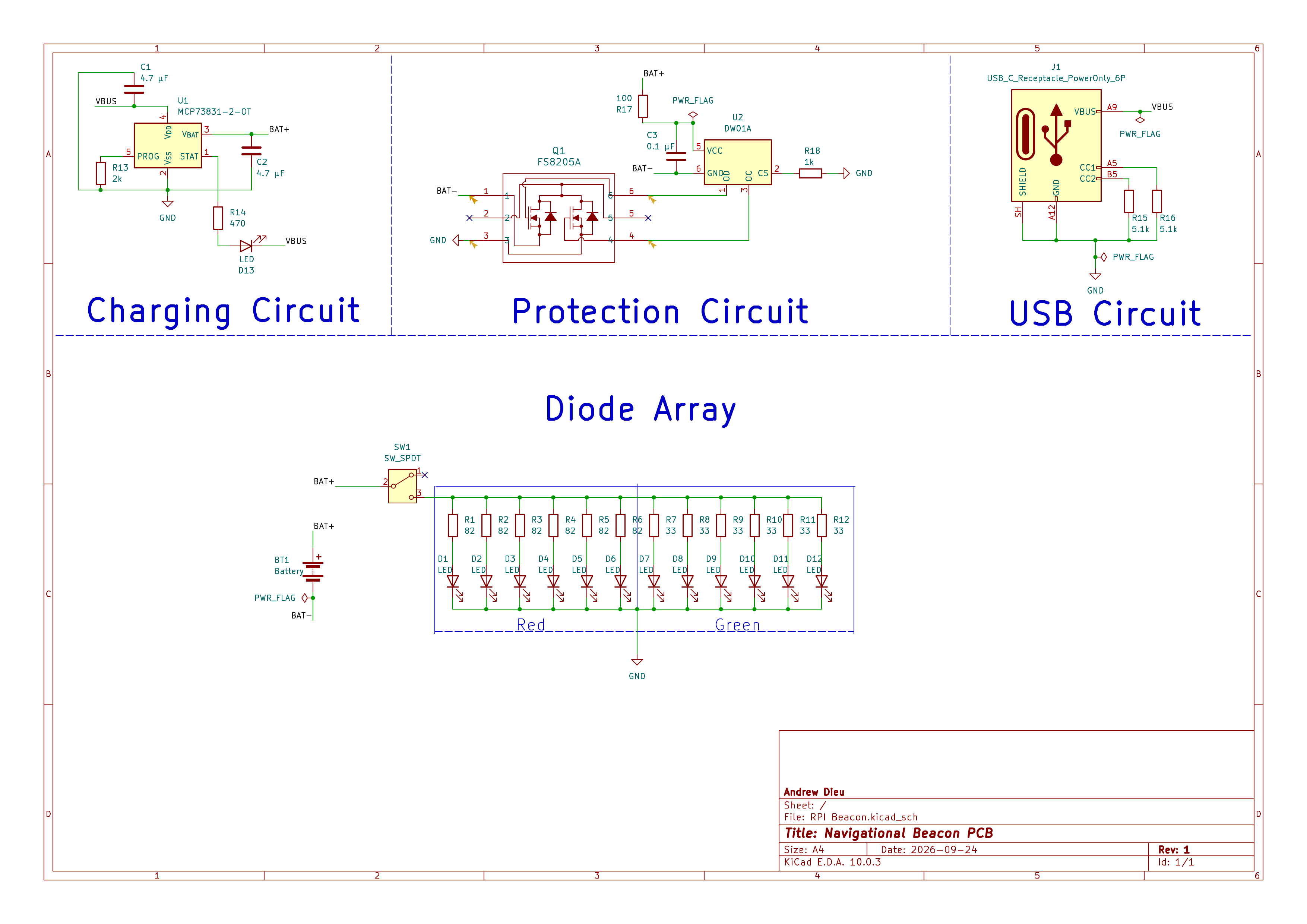
Rough breakdown:
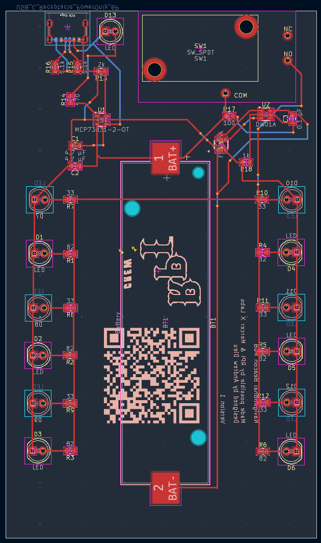
PCB Dimensions are exactly 75mm x 127mm
Rough Napkin math calculates about 10 to 12 hours on a 2500 to 2800 mAh cell. Brightness drops as the battery drains, green more so than red, so expect around 7 to 8 hours at good brightness.
| Ref | Qty | Part | Value / Part # | Footprint |
|---|---|---|---|---|
| U1 | 1 | Li-ion charger | 4.2 V, 500 mA / MCP73831T-2ACI/OT | Package_TO_SOT_SMD:SOT-23-5 |
| U2 | 1 | Battery protection IC | DW01A | Package_TO_SOT_SMD:SOT-23-6 |
| Q1 | 1 | Dual N-MOSFET (protection switch) | FS8205A | Package_TO_SOT_SMD:SOT-23-6 |
| C1, C2 | 2 | Charger input/output capacitors | 4.7 uF, 10 V, X5R | Capacitor_SMD:C_0805_2012Metric |
| C3 | 1 | DW01A supply filter capacitor | 0.1 uF | Capacitor_SMD:C_0805_2012Metric |
| R1-R6 | 6 | Red LED resistors (one per LED) | 82 Ohm | Resistor_SMD:R_0805_2012Metric |
| R7-R12 | 6 | Green LED resistors (one per LED) | 33 Ohm | Resistor_SMD:R_0805_2012Metric |
| R13 | 1 | Charge current set (PROG) | 2 kOhm | Resistor_SMD:R_0805_2012Metric |
| R14 | 1 | Charge status LED resistor | 470 Ohm | Resistor_SMD:R_0805_2012Metric |
| R15, R16 | 2 | USB-C CC pulldowns | 5.1 kOhm | Resistor_SMD:R_0805_2012Metric |
| R17 | 1 | DW01A VCC resistor | 100 Ohm | Resistor_SMD:R_0805_2012Metric |
| R18 | 1 | DW01A CS resistor | 1 kOhm | Resistor_SMD:R_0805_2012Metric |
| D1-D6 | 6 | Nav LEDs | Red 5 mm, clear lens | LED_THT:LED_D5.0mm |
| D7-D12 | 6 | Nav LEDs | Green 5 mm, clear lens | LED_THT:LED_D5.0mm |
| D13 | 1 | Charge status LED | Yellow 5 mm | LED_THT:LED_D5.0mm |
| J1 | 1 | USB-C power-only receptacle | 6-pin / GCT USB4125-GF-A | Connector_USB:USB_C_Receptacle_GCT_USB4125-xx-x_6P_TopMnt_Horizontal |
| SW1 | 1 | Lever microswitch, SPDT | Omron V-152-1C25 | Custom V-152-1C25 (project library) |
| BT1 | 1 | 18650 PCB-mount holder | Keystone 1042 | Battery:BatteryHolder_Keystone_1042_1x18650 |
| - | 1 | 18650 cell, unprotected | Samsung 25R, Molicel P28A, or similar | — |
| - | 2-4 | Mounting hardware | M3 / Screws, nuts, standoffs | MountingHole:MountingHole_3.2mm_M3 |
Original design by RowKraft LLC (rowkraft.com), 2012. This is a from-scratch redraw based on a board I took apart, not their files btw please don't sue.
| Qty | Value | Footprint | References |
|---|---|---|---|
| 13 | LED | LED_THT:LED_D5.0mm | D1, D2, D3, D4, D5, D6, D7, D8, D9, D10, D11, D12, D13 |
| 6 | 33 | Resistor_SMD:R_0805_2012Metric | R7, R8, R9, R10, R11, R12 |
| 6 | 82 | Resistor_SMD:R_0805_2012Metric | R1, R2, R3, R4, R5, R6 |
| 2 | 4.7 µF | Capacitor_SMD:C_0805_2012Metric | C1, C2 |
| 2 | 5.1k | Resistor_SMD:R_0805_2012Metric | R15, R16 |
| 1 | 0.1 µF | Capacitor_SMD:C_0805_2012Metric | C3 |
| 1 | 100 | Resistor_SMD:R_0805_2012Metric | R17 |
| 1 | 1k | Resistor_SMD:R_0805_2012Metric | R18 |
| 1 | 2k | Resistor_SMD:R_0805_2012Metric | R13 |
| 1 | 470 | Resistor_SMD:R_0805_2012Metric | R14 |
| 1 | Battery | Battery:BatteryHolder_Keystone_1042_1x18650 | BT1 |
| 1 | DW01A | Package_TO_SOT_SMD:SOT-23-6 | U2 |
| 1 | FS8205A | FS8205A:SOT-23-6L_TCP | Q1 |
| 1 | LOGO | LOGO | G*** |
| 1 | MCP73831-2-OT | Package_TO_SOT_SMD:SOT-23-5 | U1 |
| 1 | SW_SPDT | V-152-1C25:V-152-1C25 | SW1 |
| 1 | USB_C_Receptacle_PowerOnly_6P | Connector_USB:USB_C_Receptacle_GCT_USB4125-xx-x_6P_TopMnt_Horizontal | J1 |
iandchasse/silkscreen-pcb
Silkscreen: open-hardware ESP32-S3 e-paper reader mainboard (KiCad 9). Formerly the de-link hub.


Xii-Labs/Xii-Boy-Ultra
The world's first wire-free Wii portable, now in the palm of your hands. Better than ever, optimized to delight, built for fun. The next generation of Wii portables starts now.

RobieElliz/esp32InductanceMeterV2
Portable ESP32 Inductance Meter: A low-cost, high-precision tool with dual 100nF/5µF refs, a TLV3202 comparator, fast USB-C (IP2312) charging, and a 2.4-inch OLED display for real-time readings.


user-will/PCB_CANNONBALL
An ESP32-C3 dev board with more sensors and features then you could know what to do with

I-AM-ENGINEER/AudMX
Alternative for Deej ( https://github.com/omriharel/deej ) with more features

tor1kk/bms-buck-boost
Battery Management System (BMS) with Buck-Boost Converter
It measures 75 × 127 mm and has 2 copper layers, 1.6 mm thick.
41 parts, built around the DW01A and FS8205A. The full list of its parts is on this page, with links to each part's symbol and footprint where PCBKit's library has them.
From the computersandrew/Modular-Boat-Beacon-Light repository on GitHub, at the commit this page was made from: the board is RPI Beacon.kicad_pcb and its schematic RPI Beacon.kicad_sch. PCBKit opens the board in the browser, with nothing to install.
Its repository states no licence, so its author keeps all rights: ask computersandrew before reusing the design.