4 layers102.4 × 83.1 mm

 RobieElliz/esp32InductanceMeterV220
Portable ESP32 Inductance Meter: A low-cost, high-precision tool with dual 100nF/5µF refs, a TLV3202 comparator, fast USB-C (IP2312) charging, and a 2.4-inch OLED display for real-time readings.
Inductance Meter V2-0 is an open-source printed circuit board by RobieElliz, from the RobieElliz/esp32InductanceMeterV2 repository on GitHub, published under the MIT licence. It is a 2-layer board of 94 × 99 mm with 86 parts on 79 nets, routed with 447 tracks and 111 vias.
It is built around the ESP32-WROOM-32U, DW01A and IP2312U, with the TLV3202AIDR(LX), FS8205A and G5V-1-DC3 among its other parts. Its parts include 28 resistors, 17 capacitors, 8 ICs, 6 diodes and 4 connectors. It belongs with the lEDs and displays boards and the ESP32 boards of this library.



A DIY ESP32-based inductance meter designed to bridge the gap in electronics testing. Developed at the Polytechnic University of the Philippines, this low-cost, high-precision tool is ideal for students, researchers, and hobbyists.
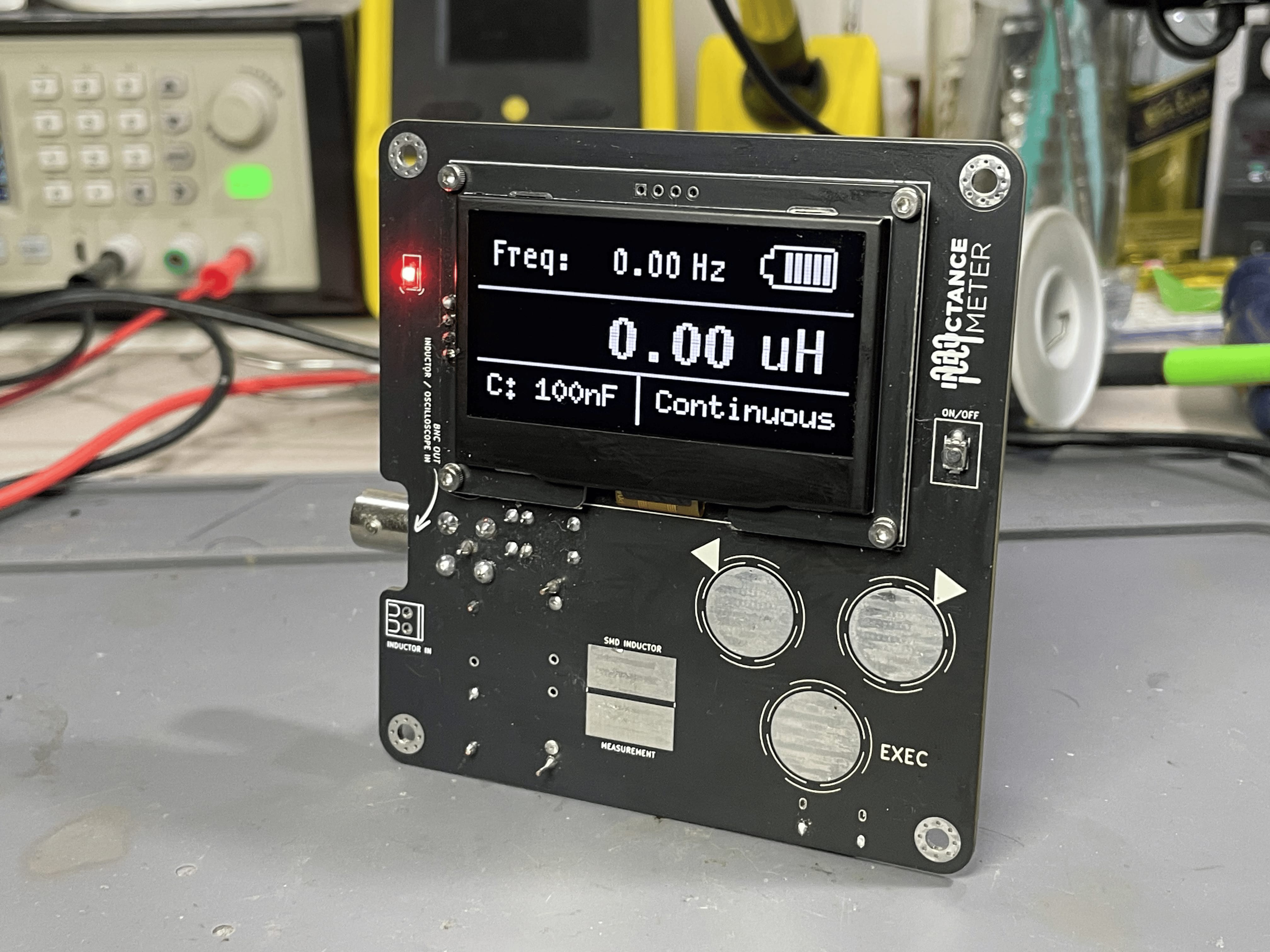
Accurate inductance measurement is crucial in electronics. Yet, professional meters are often expensive and inaccessible. This project provides an affordable alternative for educational and experimental applications.
Using LC resonance principles, the device:
By democratizing access to essential testing equipment, this project empowers the next generation of engineers to innovate and experiment without breaking the bank.
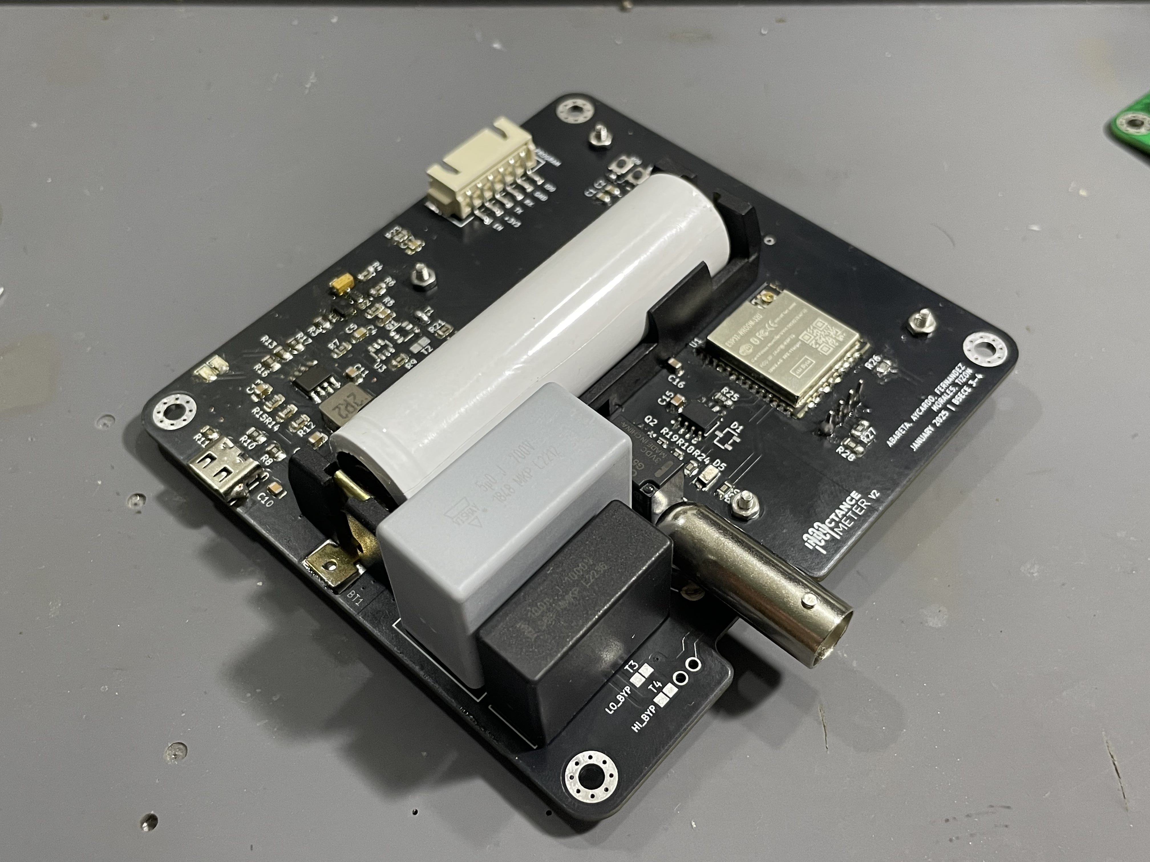
This project is open source. See the LICENSE file for more details.
This project is made by:
Johanna Abareta, Ken Louise Aycardo, Katrina Dianne Fernandez, Vince Morales, Robie Elliz Tizon
| Qty | Value | Footprint | References |
|---|---|---|---|
| 6 | 10K | Resistor_SMD:R_0805_2012Metric_Pad1.20x1.40mm_HandSolder | R1, R2, R19, R23, R27, R28 |
| 5 | 22uF | Capacitor_SMD:C_0805_2012Metric_Pad1.18x1.45mm_HandSolder | C4, C11, C12, C13, C16 |
| 4 | 100R | Resistor_SMD:R_0805_2012Metric_Pad1.20x1.40mm_HandSolder | R7, R16, R17, R24 |
| 4 | M3 Pad | MountingHole:MountingHole_3.2mm_M3_Pad_Via | H1, H2, H3, H4 |
| 4 | Solderable Tie | easyeda2kicad:Net-Tie 0805 Based | T1, T2, T3, T4 |
| 3 | 100nF | Capacitor_SMD:C_0805_2012Metric_Pad1.18x1.45mm_HandSolder | C1, C2, C17 |
| 3 | LED | LED_SMD:LED_0805_2012Metric_Pad1.15x1.40mm_HandSolder | D2, D3, D6 |
| 3 | Touch | Robie_Customs:Touch_Pad_ESP | J2, J3, J4 |
| 2 | 100K | Resistor_SMD:R_0805_2012Metric_Pad1.20x1.40mm_HandSolder | R5, R6 |
| 2 | 150R | Resistor_SMD:R_0805_2012Metric_Pad1.20x1.40mm_HandSolder | R20, R26 |
| 2 | 1K | Resistor_SMD:R_0805_2012Metric_Pad1.20x1.40mm_HandSolder | R9, R18 |
| 2 | 1N4007 A7 | easyeda2kicad:SOD-123FL_L2.8-W1.8-LS3.7-RD | D4, D5 |
| 2 | 1uF | Capacitor_SMD:C_0805_2012Metric_Pad1.18x1.45mm_HandSolder | C14, C15 |
| 2 | 47K | Resistor_SMD:R_0805_2012Metric_Pad1.20x1.40mm_HandSolder | R12, R13 |
| 2 | 5.1K | Resistor_SMD:R_0805_2012Metric_Pad1.20x1.40mm_HandSolder | R8, R10 |
| 2 | LOGO | images:Inductance Meter Logo | G***, G*** |
| 1 | 0.5R | Resistor_SMD:R_0805_2012Metric_Pad1.20x1.40mm_HandSolder | R14 |
| 1 | 100n | Capacitor_SMD:C_0805_2012Metric | C5 |
| 1 | 100nF MKP | easyeda2kicad:CAP-TH_L26.0-W8.0-P22.50-D0.8 | U5 |
| 1 | 100nF MLCC | easyeda2kicad:CAP-TH_L5.5-W3.2-P5.00-D0.5 | C7 |
| 1 | 18650 | easyeda2kicad:BATTERY-SMD_18650-1S-L77.1-W20.7-1 | BT1 |
| 1 | 1M | Resistor_SMD:R_0805_2012Metric_Pad1.20x1.40mm_HandSolder | R11 |
| 1 | 1uF CBB | easyeda2kicad:CAP-TH_L26.0-W11.1-P22.50-D1.4 | C9 |
| 1 | 1uH | Inductor_SMD:L_1008_2520Metric | L1 |
| 1 | 2.2nF | Capacitor_SMD:C_0805_2012Metric | C10 |
| 1 | 2.2uH | easyeda2kicad:IND-SMD_L7.1-W6.6 | L2 |
| 1 | 33R | Resistor_SMD:R_0805_2012Metric_Pad1.20x1.40mm_HandSolder | R25 |
| 1 | 4.7uF MLCC | easyeda2kicad:CAP-TH_L5.5-W3.2-P5.00-D0.5 | C8 |
| 1 | 40K | Resistor_SMD:R_0805_2012Metric | R21 |
| 1 | 47uF | Capacitor_SMD:C_0805_2012Metric_Pad1.18x1.45mm_HandSolder | C3 |
| 1 | 50K | Resistor_SMD:R_0805_2012Metric | R22 |
| 1 | 511K | Resistor_SMD:R_0805_2012Metric_Pad1.20x1.40mm_HandSolder | R3 |
| 1 | 51K | Resistor_SMD:R_0805_2012Metric_Pad1.20x1.40mm_HandSolder | R15 |
| 1 | 5uF MKP | easyeda2kicad:CAP-TH_L32.0-W16.0-P27.50-D0.8 | C6 |
| 1 | 91K | Resistor_SMD:R_0805_2012Metric_Pad1.20x1.40mm_HandSolder | R4 |
| 1 | BAT54-7-F | easyeda2kicad:SOT-23-3_L2.9-W1.6-P1.90-LS2.8-BR | D1 |
| 1 | BNC | easyeda2kicad:BNC-TH_DOSIN-801-0051 | RF1 |
| 1 | BOOT | easyeda2kicad:SW-SMD_L3.9-W3.0-P4.45 | SW1 |
| 1 | DW01A | Package_TO_SOT_SMD:SOT-23-6 | U3 |
| 1 | ENABLE | easyeda2kicad:SW-SMD_L3.9-W3.0-P4.45 | SW2 |
| 1 | ESP32-WROOM-32U | RF_Module:ESP32-WROOM-32U | U1 |
| 1 | FS8205A | easyeda2kicad:SOT-23-6_L2.9-W1.6-P0.95-LS2.8-BR | Q1 |
| 1 | G5V-1-DC3 | easyeda2kicad:RELAY-TH_G5V-1 | K1 |
| 1 | IP2312 | easyeda2kicad:SOP-8_L4.9-W3.9-P1.27-LS6.0-BL-EP | U6 |
| 1 | LOGO | images:arrow | G*** |
| 1 | ON-OFF | easyeda2kicad:SW-SMD_L3.9-W3.0-P4.45 | SW3 |
| 1 | S Term | easyeda2kicad:CONN-TH_2P-P2.54_MX128-2.54-GN01-02P-CU-Y-A | J1 |
| 1 | SMD L | easyeda2kicad:IND-SMD_L7.1-W6.6 | L3 |
| 1 | SS8050 | Package_TO_SOT_SMD:SOT-23 | Q2 |
| 1 | TLV3202AIDR | easyeda2kicad:SOIC-8_L4.9-W3.9-P1.27-LS6.0-BL | U4 |
| 1 | TPS631000DRLR | easyeda2kicad:SOT-583-8_L2.1-W1.2-P0.50-LS1.6-BL | U2 |
| 1 | TYPE-C 6P(073) | easyeda2kicad:TYPE-C-SMD_TYPE-C-6P_5 | USB1 |
| 1 | XH UART | easyeda2kicad:CONN-SMD_S6B-XH-SM4-TB-LF-SN | U7 |
| 1 | ~ | easyeda2kicad:2.4 OLED I2C | U8 |


RyanHailey21/neuromorphic-ir-event-sensor
Neuromorphic Infrared Event Sensor (Rev A) - 4-Quadrant Temporal Contrast Analog Front-End in KiCad 10

AhmedOsama21998/SmartWatch-ESP32-S3-PCB
ESP32-S3 smartwatch PCB with Li-ion battery charging, protection, and power management. Work in progress; sensor integration is planned.


Pedro-Seixas/Smartwatch
A custom-designed smartwatch built around the ESP32-S3, combining BLE connectivity, a rectangular touch display, recharge capability, IMU and temperature sensors. Designed from the ground up in KiCad.

Sumya99/RobotCarPCB
NAND сургалтын төвийн сурагчдад зориулсан робот машины PCB төсөл

ZharbolatDinmukhamed/Haptic-Glove-PCB
A wrist-mounted PCB for a haptic feedback glove, developed as part of my Research Assistantship at the Tactile Laboratory, Nazarbayev University.
It measures 94 × 99 mm and has 2 copper layers, 1.6 mm thick.
86 parts, built around the ESP32-WROOM-32U, DW01A, IP2312U and TLV3202AIDR(LX). The full list of its parts is on this page, with links to each part's symbol and footprint where PCBKit's library has them.
From the RobieElliz/esp32InductanceMeterV2 repository on GitHub, at the commit this page was made from: the board is Inductance Meter V2-0 - KiCAD/Inductance Meter V2-0.kicad_pcb and its schematic Inductance Meter V2-0 - KiCAD/Inductance Meter V2-0.kicad_sch. PCBKit opens the board in the browser, with nothing to install.
Its repository publishes it under the MIT licence: you may reuse it on that licence's terms (keep the author's notice, and for a copyleft licence share your changes alike).