Skip to the content
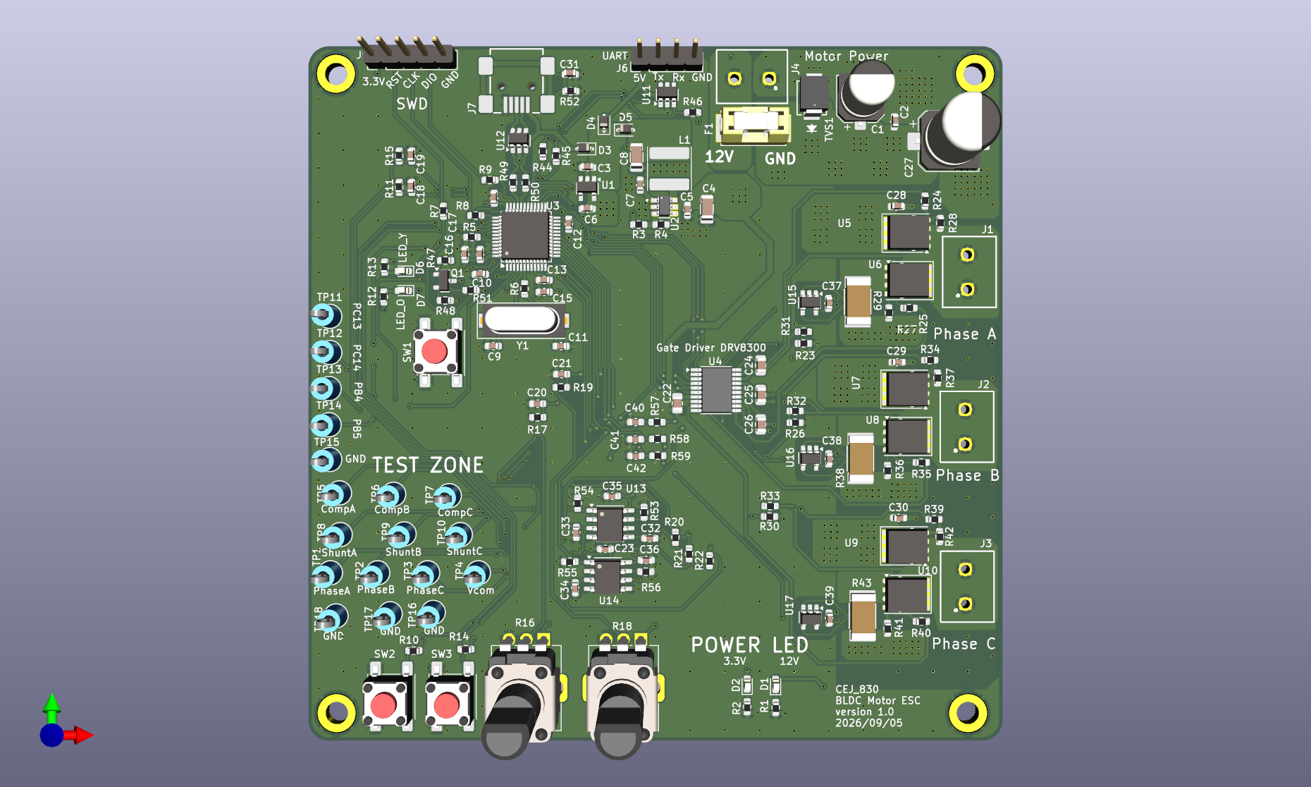
4 layers100 × 100 mmSTM32 ESC HW, the printed circuit board in 3D

STM32_BLDC_ESC_Firmware

Size
100 × 100 mm
Copper layers
4
Thickness
1.6 mm
Parts
162
Nets
100
Pads
543
Tracks, vias
1,500, 780
Pours
29
Routed
Yes
KiCad
KiCad 9.0 (file 20241229)
Created
2 Oct 2026
Updated
4 Nov 2026

Overview

STM32 ESC HW is an open-source printed circuit board by cej830, from the cej830/STM32_BLDC_ESC_Firmware repository on GitHub. It is a 4-layer board of 100 × 100 mm with 162 parts on 100 nets, routed with 1,500 tracks and 780 vias.

It is built around the DRV8300DPWR-MS, TPS560430XDBVR-MS and IRFH7440TRPBF, with the TLV3202AIDR(LX), USBLC6-2SC6 and TPS7A2033PDBVR-TP among its other parts. Its parts include 59 resistors, 42 capacitors, 17 ICs, 7 diodes and 7 connectors. It belongs with the robots and motor control boards and the STM32 boards of this library.

Main components

9

README

README.md

STM32 Sensorless BLDC ESC

STM32F103C8 기반 센서리스 BLDC ESC. 회로·4-layer PCB 설계 및 펌웨어 구현을 수행하고 12V에서 A2212/13T 1000kV 모터의 무부하 구동을 확인했다.

자체 제작 ESC의 모터 구동

Highlights

  • 4층 기판 3상 ESC 하드웨어 설계부터 회로도 작성, 조립 및 보드 브링업 수행
  • 오픈루프 기동 및 BEMF(역기전력) 클로즈드 루프 정류를 적용한 센서리스 6스텝 제어 구현
  • ADC 기반 제로 크로싱 검출 방식 적용, 고듀티 구간에서는 외부 비교기 및 TIM2 Input Capture 로 전환
  • 12V 환경에서 A2212/13T 1000kV 모터를 무부하 조건에서 CCR 1750/1800까지 구동 시험 완료

Hardware

  • MCU: STM32F103C8T6
  • Gate driver / MOSFET: DRV8300 / IRFH7440 × 6
  • PCB: 4-layer, 1.6mm
  • Power: 12V→5V Buck, USB 5V와 diode ORing, 3.3V LDO
  • BEMF sensing: 상전압 ADC 입력 및 TLV3202 외부 비교기
  • Current sensing: 10mΩ 로우사이드 션트 및 INA180A3 × 3
  • Interface: USB 2.0 FullSpeed, UART, LED, 버튼, 가변저항, 테스트 포인트

회로,BOM 작성, PCB 부품 배치 및 배선, 보드 bring-up을 직접 수행했다. 부품 실장은 SMT 조립을 외주하였다.

3D Board View

Front Back

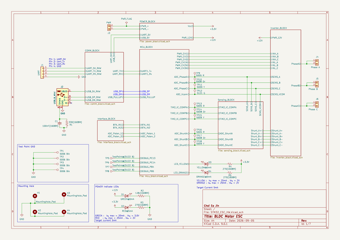
Schematic

Schematic

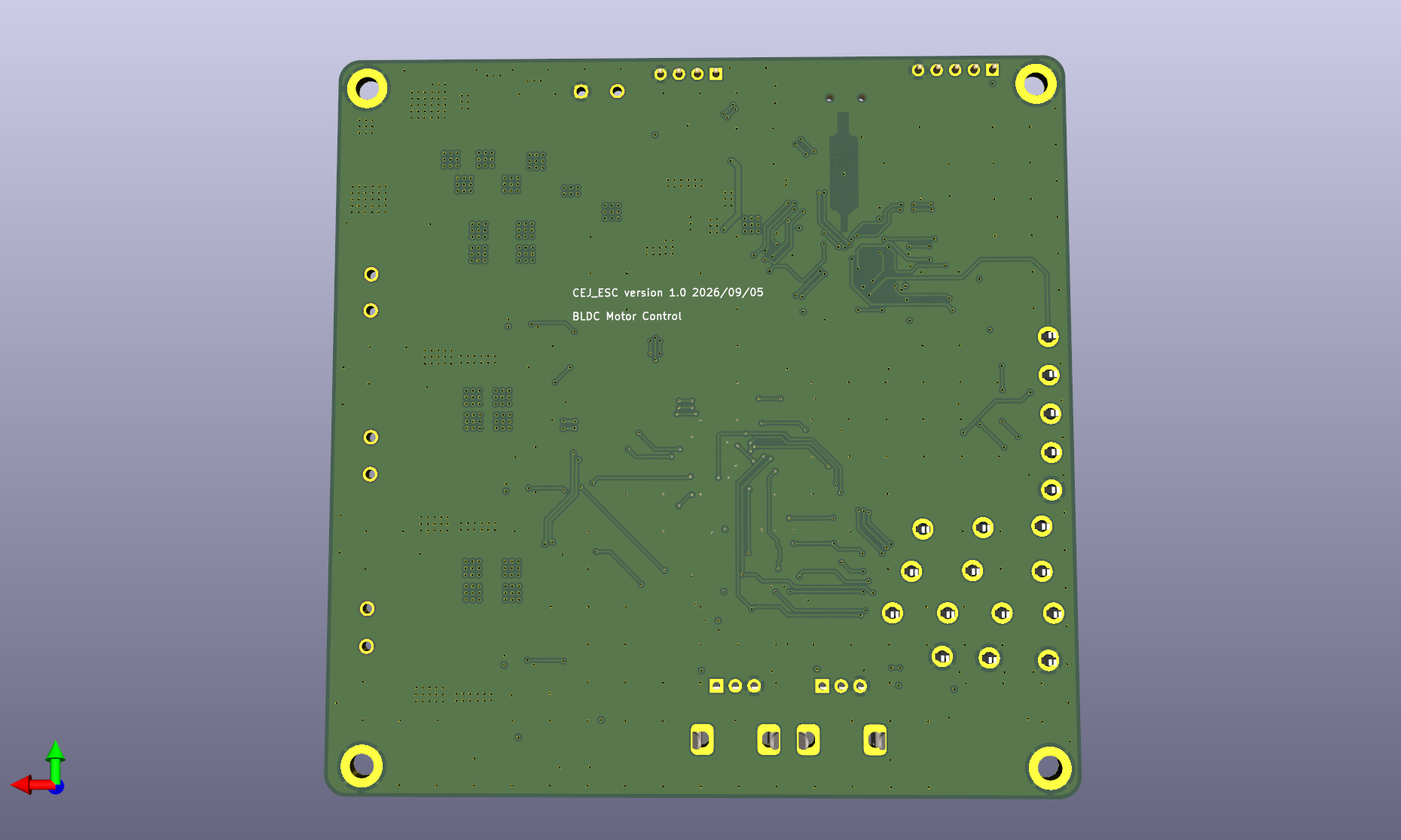
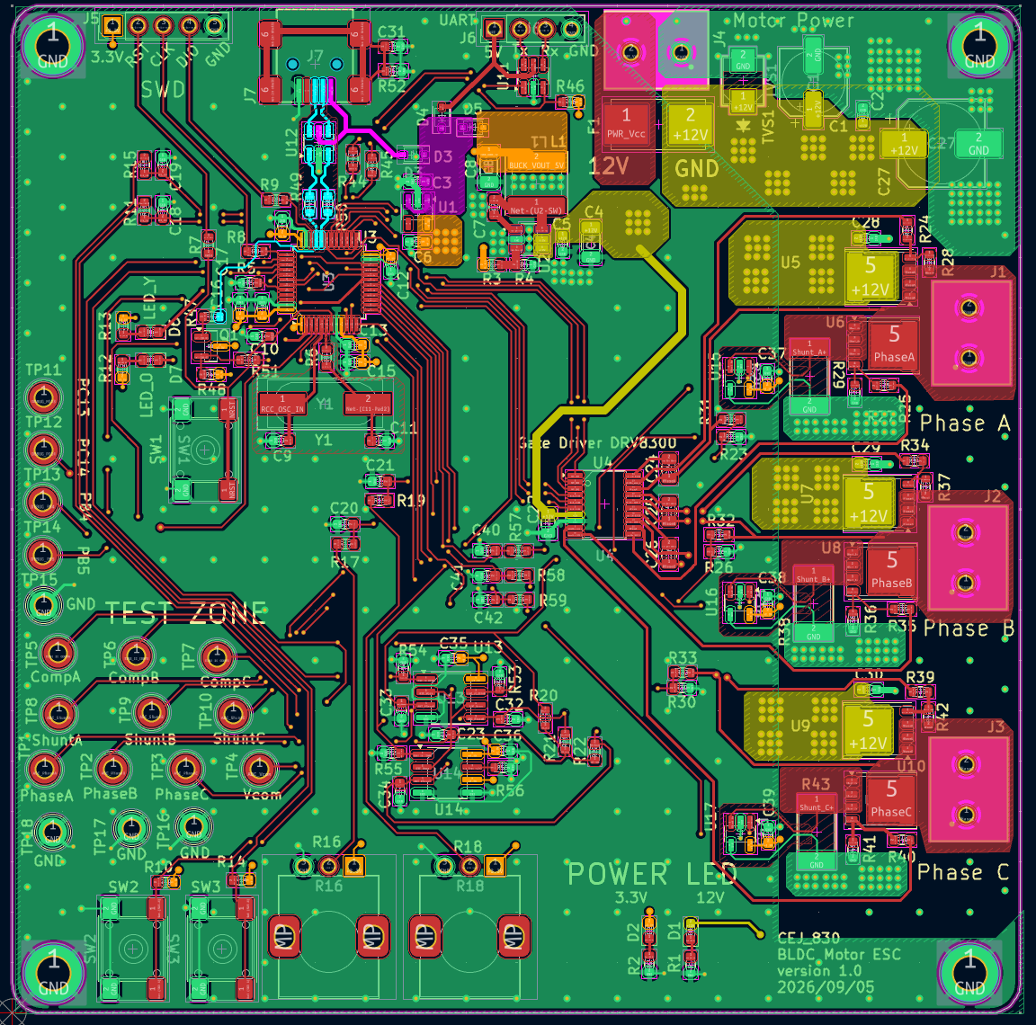
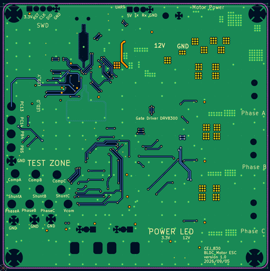
PCB Layout — Front / Back

Front Back

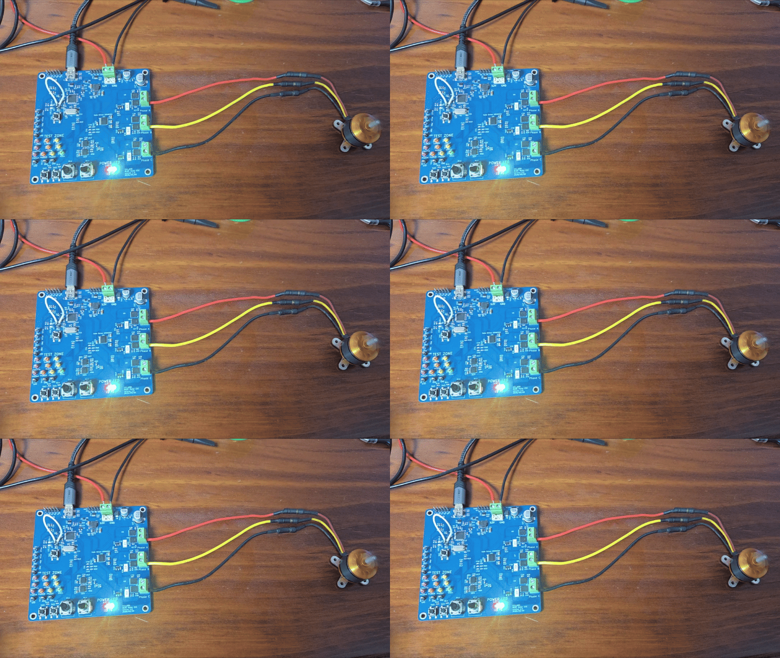
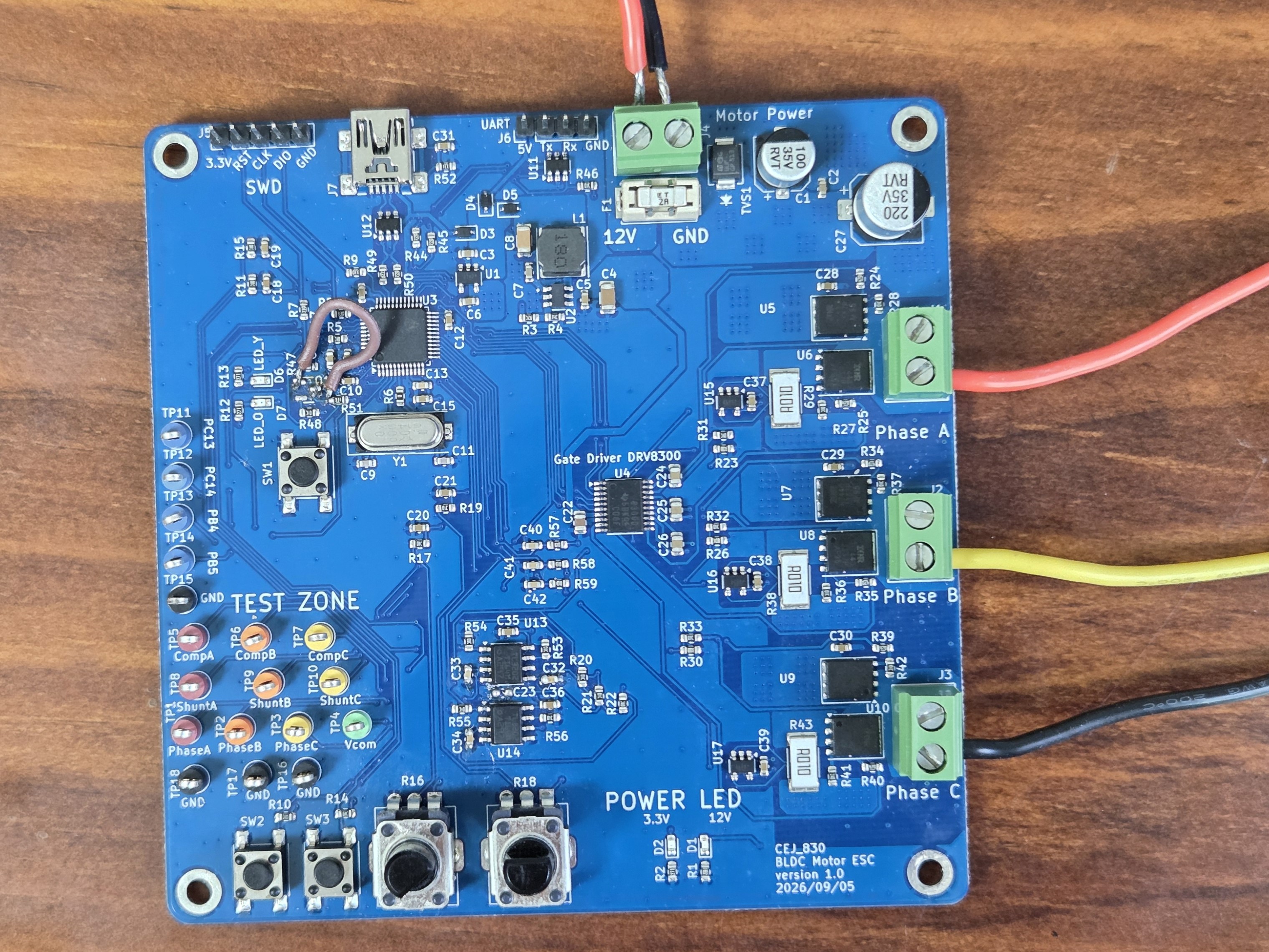
Assembled Board

조립한 ESC 보드

실물 수정: USB 풀업 저항 직결, Vcom 비교기 입력 커패시터 제거.

하드웨어 구성 상세

Firmware

C, STM32 HAL 및 레지스터 제어로 구현한 인터럽트 기반 펌웨어. Open-loop 기동 후 BEMF 기반 six-step 정류로 전환

센서리스 제어 흐름도

듀티 구간에 따라 ADC 기반 swBEMF·선형보간 또는 외부 비교기 출력의 TIM2 input capture로 ZC를 검출한다. TIM3로 다음 정류를 예약하고 TIM1 상보 PWM 출력을 갱신한다. 운전 데이터는 USB CDC로 전송한다.

제어 코드 · 주변장치·정류표 상세

Testing

Setup

  • Motor: A2212/13T 1000kV
  • Supply: 12V DC power supply
  • Load: 무부하
  • Input: 가변저항 ADC 값으로 CCR 조절
  • Observation: 오실로스코프, USB CDC 모니터

Results

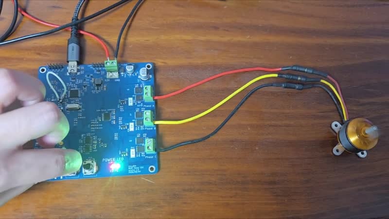
Motor Operation

모터 구동 영상 보기

구동 영상 — 무부하 운전 및 노브 조작.

항목관찰 결과
속도 조절노브 입력에 따른 CCR 및 회전 속도 변화 확인
최대 시험 설정ARR=1800, CCR=1750 — 설정 비율 약 97.2%
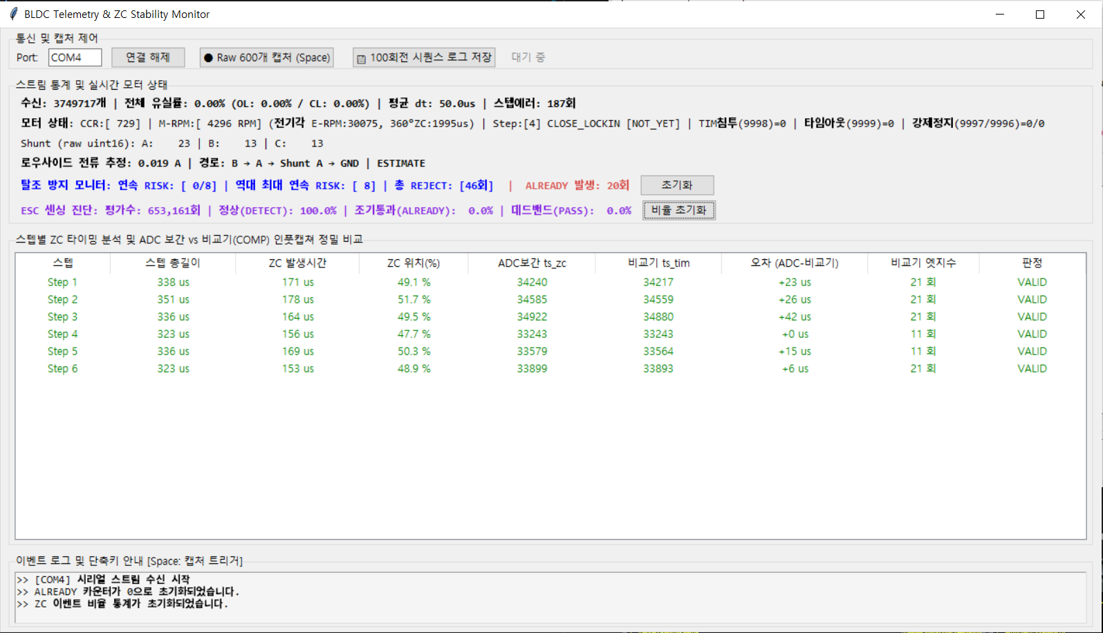
PC Monitor

USB CDC 수신 데이터 표시 및 CSV 저장. RPM은 추정값이며, 션트 전류 환산값의 정확도는 미검증.

운전 데이터 모니터

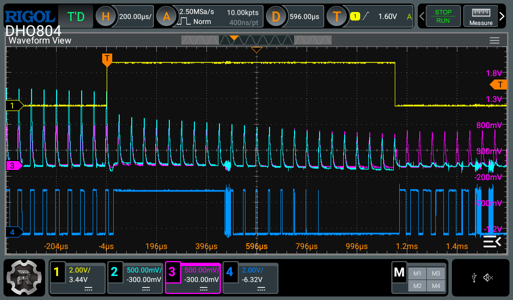
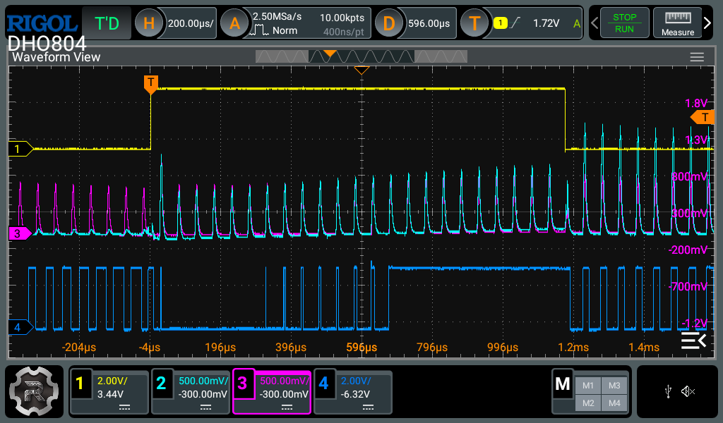
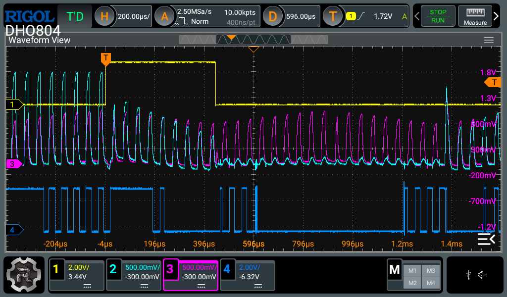
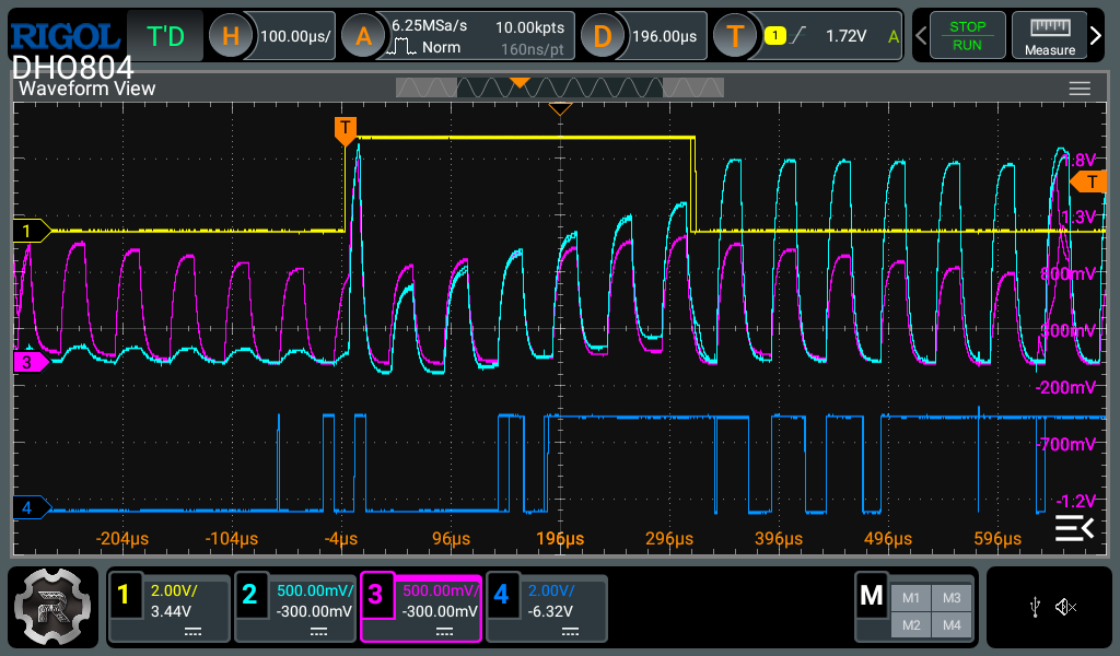
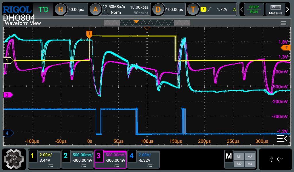
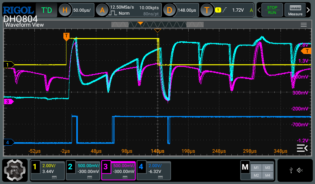
Oscilloscope

CH1: 스텝 GPIO · CH2: 플로팅 상 · CH3: Vcom · CH4: 비교기 출력.

각 행은 왼쪽 Step 1, 오른쪽 Step 2 파형으로 구성.

저듀티 CCR 220

저듀티 Step 1 저듀티 Step 2

중듀티 CCR 700

중듀티 Step 1 중듀티 Step 2

고듀티 CCR 700

고듀티 Step 1 고듀티 Step 2

Board Changes & Limitations

  • USB pull-up: 제어 MOSFET 풋프린트 오류를 배선으로 수정하고 PA12 LOW 초기화 적용. 이후 USB 인식 회복 확인.
  • Comparator: Vcom 커패시터 제거 후 고듀티에서 다중 에지 감소 관찰 및 input capture 경로 활용.
  • Current / Operation: 모터 발열 및 특정 CCR에서 구동음 발생. 전류 측정 정확도, 부하 기동, 장시간 운전, 효율·정격·보호 성능은 미검증.

개발 과정 및 디버깅 기록

Repository

위치내용
CoreDriver / Algorithm / Service / Utility 및 헤더
Drivers, Middlewares, USB_DEVICEHAL·CMSIS, 미들웨어, USB 구성
CubeMX .iocMCU 설정
ESC_Monitor수신·표시·CSV 저장 프로그램
ArchitectureHW/FW 구조와 제어 흐름

개발 환경: STM32CubeIDE, KiCad

Parts

162
QtyValueFootprintReferences
2510k(1608M)Resistor_SMD:R_0603_1608MetricR13, R14, R15, R20, R21, R24, R25, R26, R29, R30, R34, R35, R37, R38, R39, R40 +9
20100nF(1608M)Capacitor_SMD:C_0603_1608MetricC1, C3, C11, C13, C15, C17, C25, C26, C27, C31, C32, C33, C34, C35, C39, C40 +4
647(1608M)Resistor_SMD:R_0603_1608MetricR17, R18, R27, R28, R32, R33
6IRFH7440TRPBFPackage_DFN_QFN:PQFN-8-EP_6x5mm_P1.27mm_GenericU5, U6, U7, U8, U9, U10
41nF(1608M)Capacitor_SMD:C_0603_1608MetricC20, C36, C37, C38
41uF(1608M)Capacitor_SMD:C_0603_1608MetricC4, C7, C16, C18
422(1608M)Resistor_SMD:R_0603_1608MetricR53, R54, R55, R56
45006 BlkTestPoint:TestPoint_Keystone_5005-5009_CompactTP1, TP2, TP3, TP4
4MountingHole_PadMountingHole:MountingHole_3.2mm_M3_DIN965_PadH1, H2, H3, H4
4TestPoint@(5122 B)TestPoint:TestPoint_Keystone_5005-5009_CompactTP5, TP6, TP7, TP8
310m(6332M)my_lib:Shunt_R_PE2512_7m-910m Ohm_SMD_2512R22, R31, R36
31SS404Diode_SMD:D_SOD-323D5, D6, D7
31k(1608M)Resistor_SMD:R_0603_1608MetricR41, R42, R43
31uF(2012M)Capacitor_SMD:C_0805_2012MetricC21, C22, C23
32.2nF(1608M)Capacitor_SMD:C_0603_1608MetricC28, C29, C30
3270(1608M)Resistor_SMD:R_0603_1608MetricR3, R4, R5
32k(1608M)Resistor_SMD:R_0603_1608MetricR16, R19, R23
333(1608M)Resistor_SMD:R_0603_1608MetricR10, R11, R12
35005 RTestPoint:TestPoint_Keystone_5005-5009_CompactTP9, TP13, TP16
35008 OrTestPoint:TestPoint_Keystone_5005-5009_CompactTP10, TP14, TP17
35009 YTestPoint:TestPoint_Keystone_5005-5009_CompactTP11, TP15, TP18
3INA180A3Package_TO_SOT_SMD:SOT-23-5U13, U14, U15
3SW_SPSTmy_lib:Button_Switch_SMD SW_Push_1P1T SMD-4P,6x6mmSW1, SW2, SW3
210k(pot THT)my_lib:Potentiometer_Alps_RK09K_Single_VerticalR48, R50
220pF(1608M)Capacitor_SMD:C_0603_1608MetricC10, C12
2330(1608M)Resistor_SMD:R_0603_1608MetricR1, R59
2TLV3202AIDRPackage_SO:SOIC-8_3.9x4.9mm_P1.27mmU11, U12
2USBLC6-2SC6Package_TO_SOT_SMD:SOT-23-6U16, U17
10(1608M)Resistor_SMD:R_0603_1608MetricR9
10154002.DRTmy_lib:FUSE_154 Series OMNI-BLOK® Fuse and Holder AssemblyF1
11.5k(1608M)Resistor_SMD:R_0603_1608MetricR57
11.8k(1608M)Resistor_SMD:R_0603_1608MetricR2
1100uF(AEC)Capacitor_SMD:CP_Elec_6.3x7.7C2
110nF(1608M)Capacitor_SMD:C_0603_1608MetricC14
110uF(2012M)Capacitor_SMD:C_0805_2012MetricC19
118uH @SMNR6028-180MTmy_lib:Inductor SMNR6028-180MTL1
12.2uF(3216M)Capacitor_SMD:C_1206_3216MetricC5
122.1k(1608M)Resistor_SMD:R_0603_1608MetricR7
1220uF(AEC)Capacitor_SMD:CP_Elec_8x10.5C24
122uF(3216M)Capacitor_SMD:C_1206_3216MetricC9
15121 GTestPoint:TestPoint_Keystone_5005-5009_CompactTP12
188.7k(1608M)Resistor_SMD:R_0603_1608MetricR6
18MHz @ 20pFCrystal:Crystal_SMD_HC49-SDY1
1Conn_01x05Connector_PinHeader_2.54mm:PinHeader_1x05_P2.54mm_VerticalJ7
1DRV8300DPWRmy_lib:DRV8300DPWR 20-TSSOP 6.6mm _ 4.5mmU4
1GREEN@5mALED_SMD:LED_0603_1608MetricD1
1ORANGE@5mALED_SMD:LED_0603_1608MetricD4
1PWRmy_lib:TERM BLK 2POS SIDE ENTRY 5MM PCBJ3
1Phase Amy_lib:TERM BLK 2POS SIDE ENTRY 5MM PCBJ4
1Phase Bmy_lib:TERM BLK 2POS SIDE ENTRY 5MM PCBJ5
1Phase Cmy_lib:TERM BLK 2POS SIDE ENTRY 5MM PCBJ6
1RED@5mALED_SMD:LED_0603_1608MetricD2
1SMBJ13Amy_lib:TVS_Diode_SMD_SMB(DO-214AA)TVS1
1STM32F103C8TxPackage_QFP:LQFP-48_7x7mm_P0.5mmU3
1TPS560430XDBVRmy_lib:SOT-23-6(2.90 mm × 1.60 mm)U2
1TPS7A2033PDBVRPackage_TO_SOT_SMD:SOT-23-5U1
1UARTConnector_PinHeader_2.54mm:PinHeader_1x04_P2.54mm_VerticalJ1
1UMW AO3401A (PMOS)Package_TO_SOT_SMD:SOT-23Q1
1USB_B_Minimy_lib:USB_Mini B 920-462A2021S10101J2
1YELLOW@5mALED_SMD:LED_0603_1608MetricD3

Similar boards

  • 4 layers408.7 × 50 mmPartial Drawer Controller v1, the printed circuit board in 3D

    Partial Drawer Controller v1

    Robast-GmbH/PCB_Designs

    This repository contains all the necessary files and instructions for the PCBs that are designed using KiCad. Here is an overview of the main components: - .github: Contains Github-specific configurations, including…

    619 parts1MIT
  • 2 layers94 × 99 mmInductance Meter V2-0, the printed circuit board in 3D

    Inductance Meter V2-0

    RobieElliz/esp32InductanceMeterV2

    Portable ESP32 Inductance Meter: A low-cost, high-precision tool with dual 100nF/5µF refs, a TLV3202 comparator, fast USB-C (IP2312) charging, and a 2.4-inch OLED display for real-time readings.

    86 parts20MIT
  • 6 layers100 × 100 mmUsb power board, the printed circuit board in 3D

    Usb power board

    bluesatunsw/owr

    This repo includes all software necessary to operate the Test Rover Platform that is being designed and developed in the 502 project.

    409 parts5Apache-2.0
  • 2 layers80 × 57 mmDao board, the printed circuit board in 3D

    Dao board

    Decuplequart/dao_iidx_board

    古めのDAOコンの基盤の入手性がカスなのでイチから作っちゃおうというプロジェクト

    44 partsMIT
  • 2 layers50 × 70 mmNeuromorphic ir event sensor, the printed circuit board in 3D

    Neuromorphic ir event sensor

    RyanHailey21/neuromorphic-ir-event-sensor

    Neuromorphic Infrared Event Sensor (Rev A) - 4-Quadrant Temporal Contrast Analog Front-End in KiCad 10

    123 parts
  • 2 layers52 × 29 mmController, the printed circuit board in 3D

    Controller

    DaringCuteSeal/spinetime

    A neurodivergent-friendly linear clock gadget for time management in binder journals.

    42 parts3
  • 2 layers89.8 × 41.5 mmBat rf, the printed circuit board in 3D

    Bat rf

    dwanpo/balancer

    105 parts1
  • 4 layers78.5 × 55 mmRUDRAKINUXIS Lite, the printed circuit board in 3D

    RUDRAKINUXIS Lite

    RaviKachhwaha/RUDRAKINUXIS-Lite

    It is a high-performance 600W (20V–25.2V 6S) FOC BLDC ESC for UAVs & robotics. Powered by STM32G431 CORDIC MCU, it features 16 AWG wire-reinforced 2oz copper pads for motor/power, an integrated flight controller bus…

    111 parts

Questions

How big is the STM32 ESC HW PCB?

It measures 100 × 100 mm and has 4 copper layers, 1.6 mm thick.

What parts does the STM32 ESC HW use?

162 parts, built around the DRV8300DPWR-MS, TPS560430XDBVR-MS, IRFH7440TRPBF and TLV3202AIDR(LX). The full list of its parts is on this page, with links to each part's symbol and footprint where PCBKit's library has them.

Where can I download the STM32 ESC HW KiCad files?

From the cej830/STM32_BLDC_ESC_Firmware repository on GitHub, at the commit this page was made from: the board is HardWare/STM32_ESC_HW.kicad_pcb and its schematic HardWare/STM32_ESC_HW.kicad_sch. PCBKit opens the board in the browser, with nothing to install.

Can I use the STM32 ESC HW design in my own project?

Its repository states no licence, so its author keeps all rights: ask cej830 before reusing the design.