
2 layers86.4 × 75.8 mm
 CharHanMaker/CharHanMaker
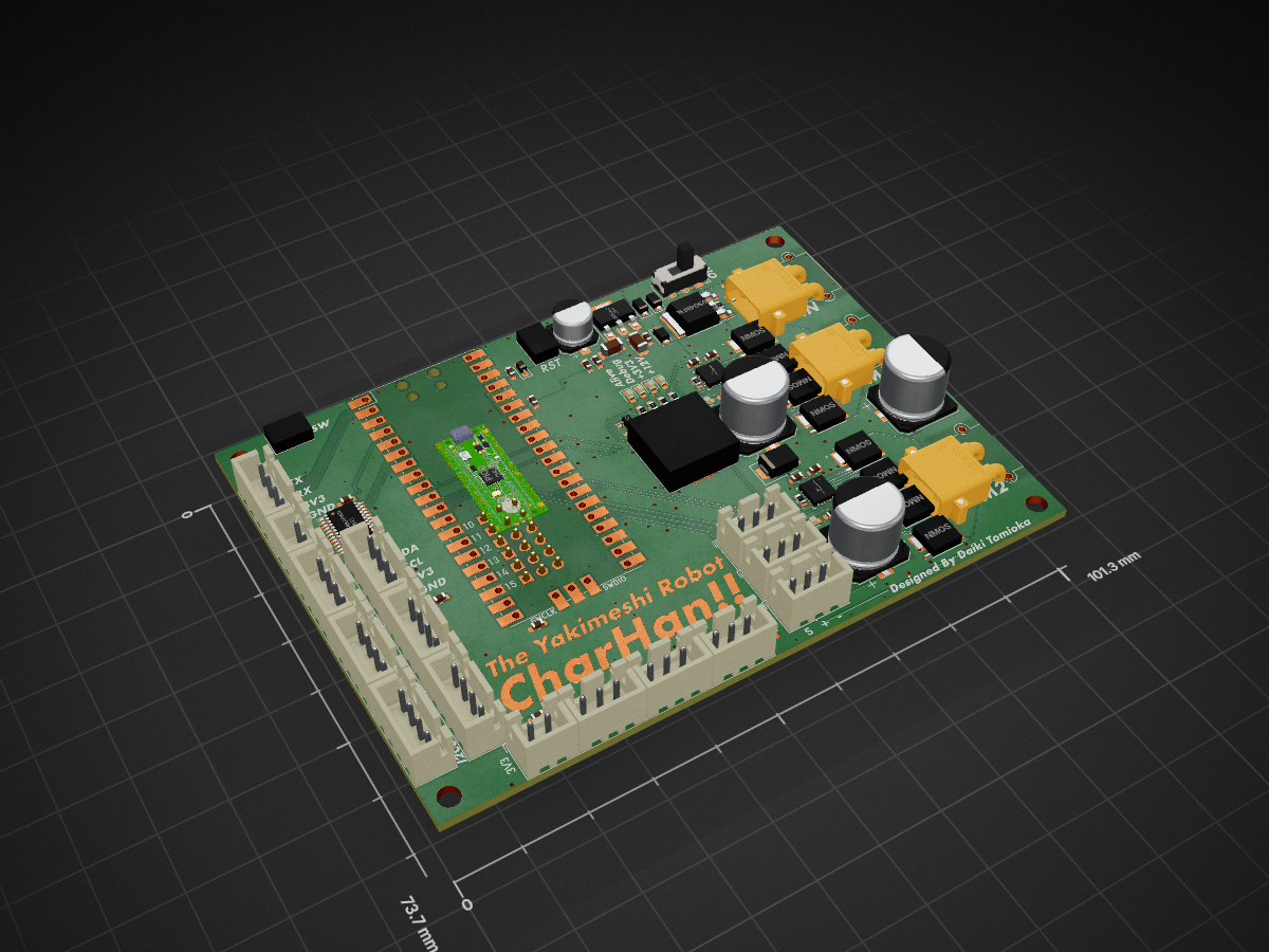
MotorDriver is an open-source printed circuit board by CharHanMaker, from the CharHanMaker/CharHanMaker repository on GitHub. It is a 2-layer board of 101.3 × 73.7 mm with 95 parts on 91 nets, routed with 568 tracks and 254 vias.
It is built around the DRV8701ERGET, AZ1117CH-3.3TRG1 and XT30PW-M, with the PKLCS1212E4001-R1 and TJ60S04M3L-VB among its other parts. Its parts include 24 connectors, 21 capacitors, 20 resistors, 10 diodes and 10 transistors. It belongs with the robots and motor control boards and the RP2040 boards of this library.


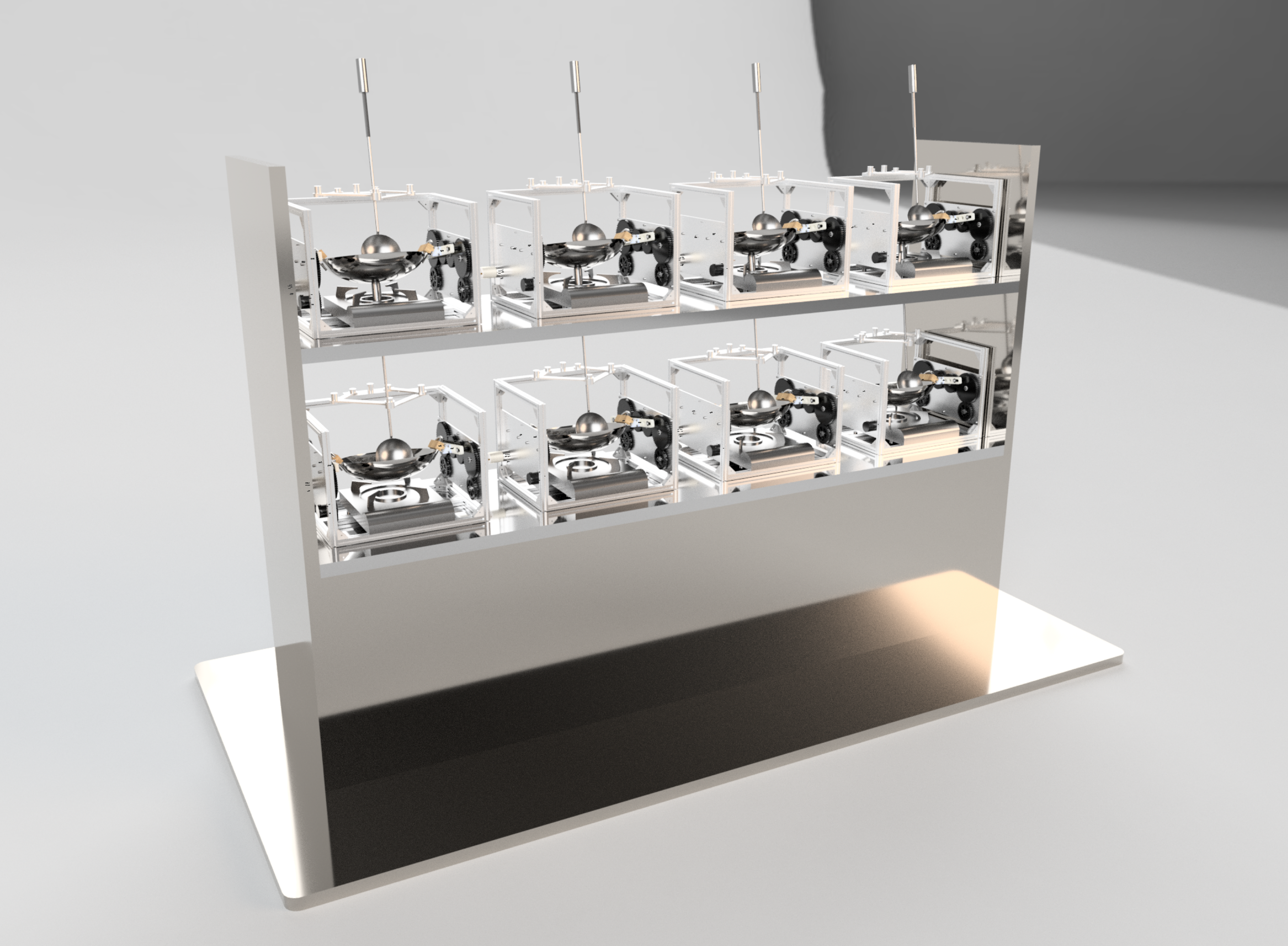
チャーハンの調理を自動化するCharHan!!というロボットを作りました。
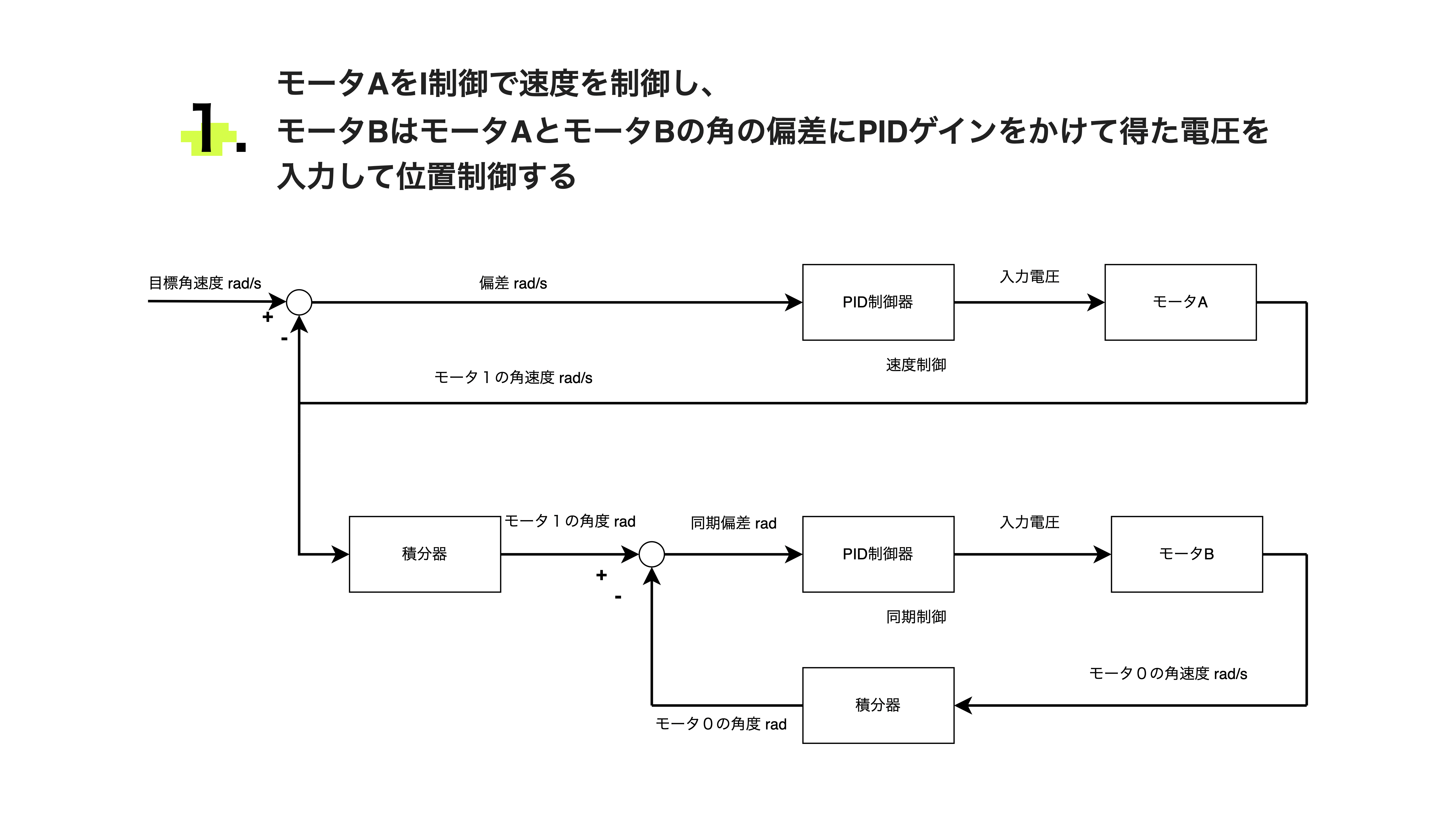
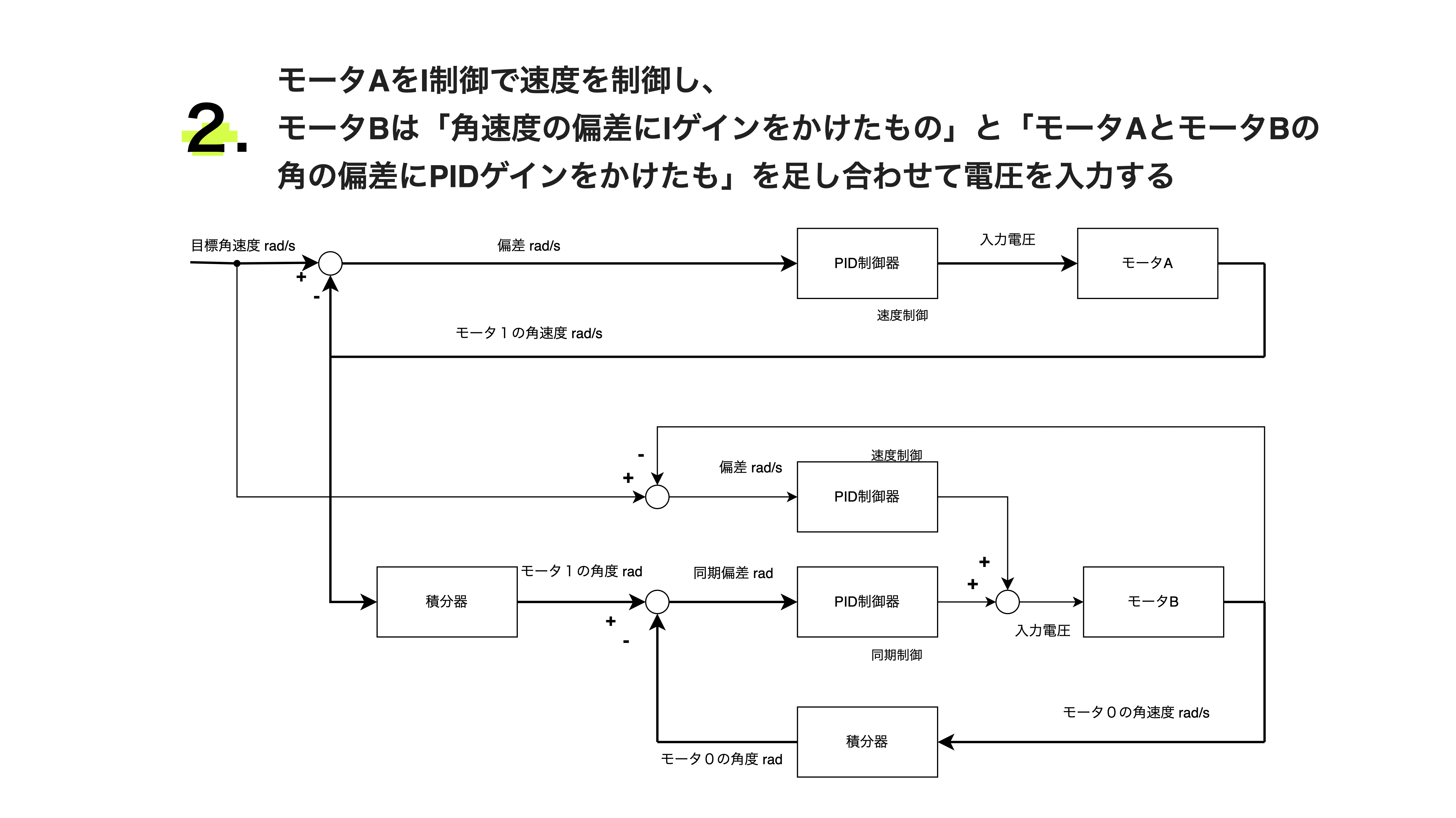
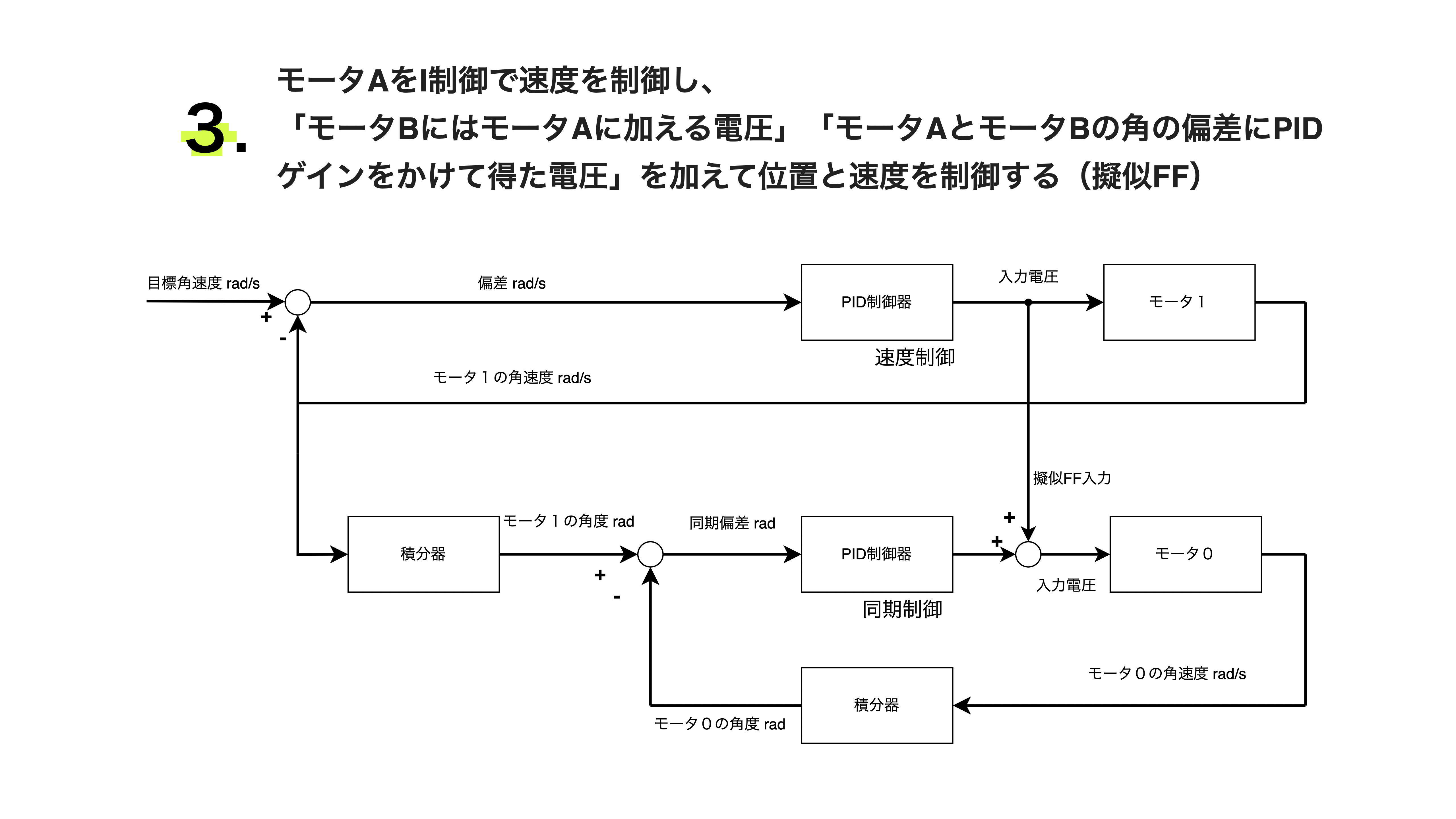
案2を採用しました。
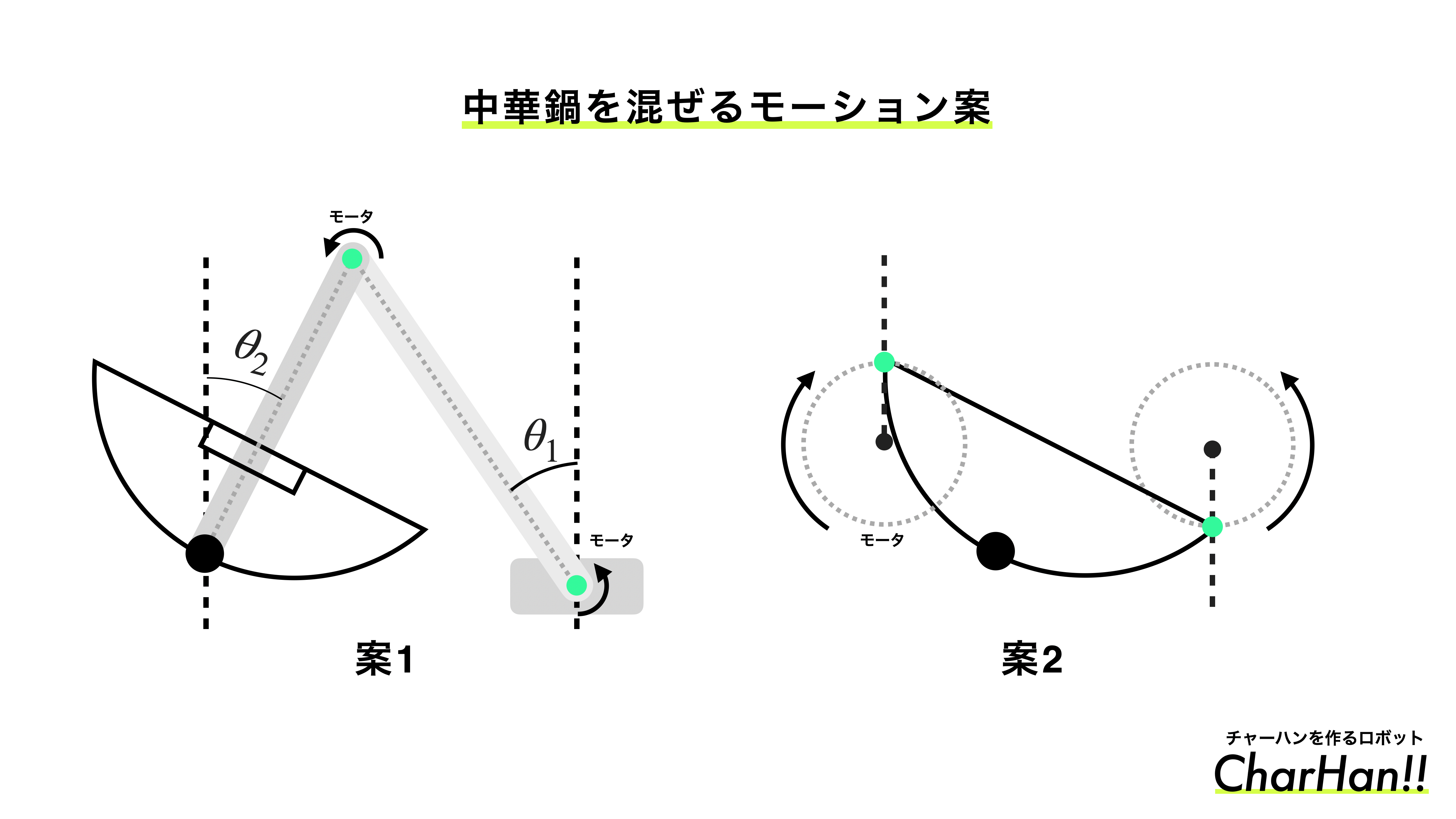
左右にモータを取り付けて左右の回転の同期する制御を入れています。
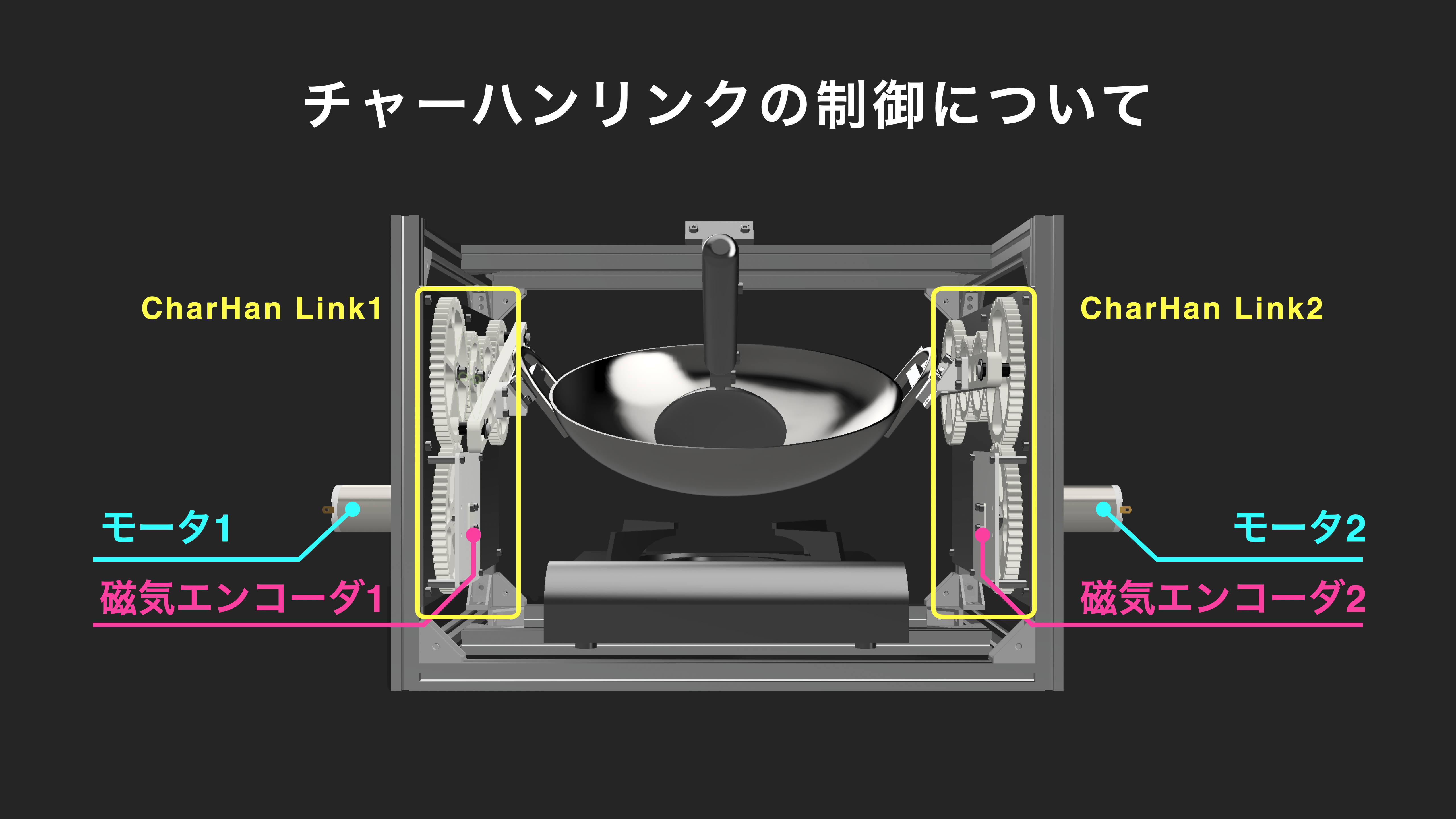
左右のリンクにエンコーダを搭載しており、角度と速度を左右で同期しています。
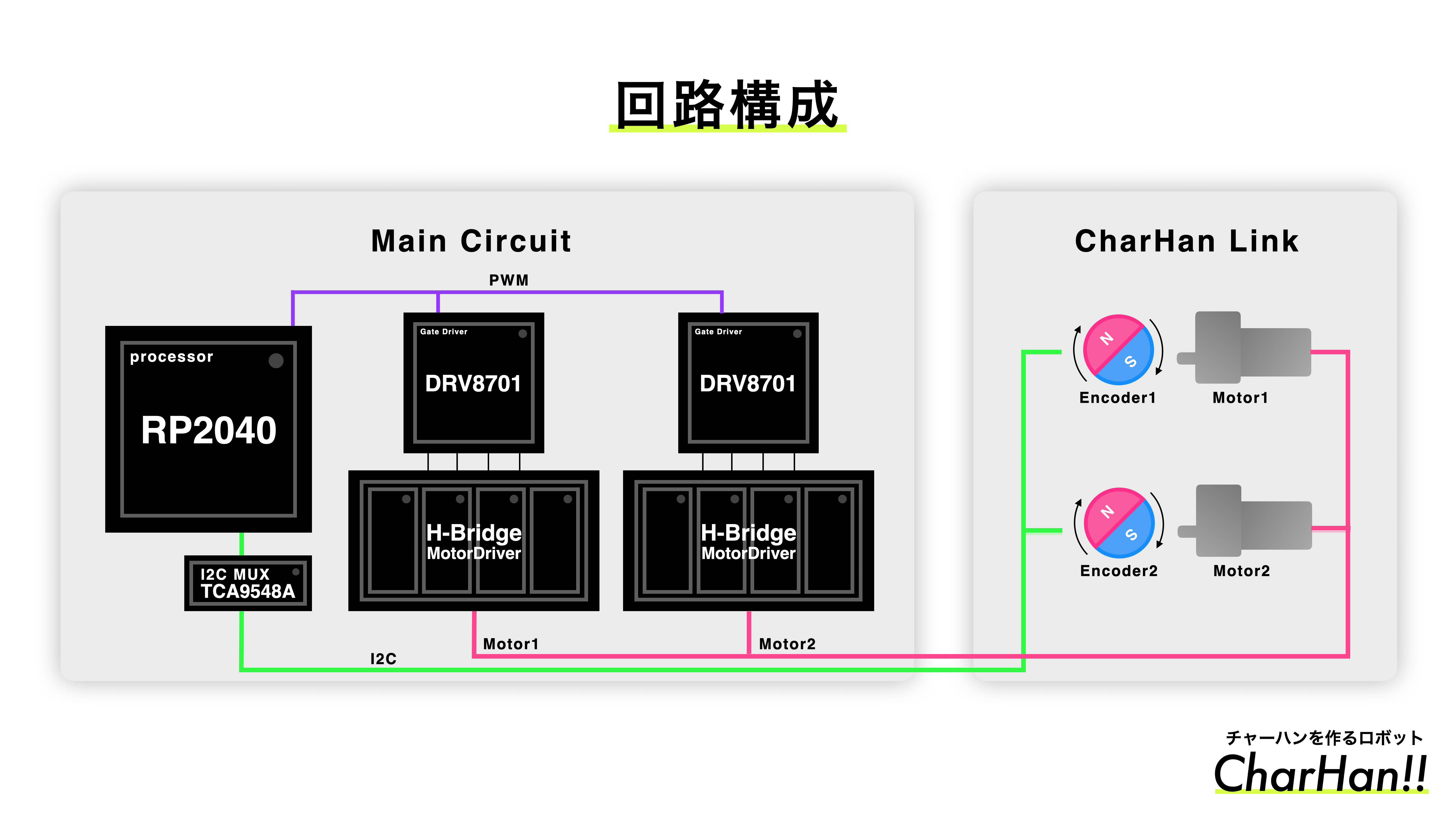
制御器は3種類設計し、評価しました。
このようなチャーハンファームを作ることで省人化できるのではないかと思っております。
Program/main_tomix/src/Modes/SystemIdentification2Program/main_tomix/src/Modes/SystemIdentification2| Qty | Value | Footprint | References |
|---|---|---|---|
| 11 | 0.1u | Capacitor_SMD:C_0603_1608Metric_Pad1.08x0.95mm_HandSolder | C4, C5, C8, C9, C10, C13, C15, C16, C18, C19, C20 |
| 8 | 4.7k | Resistor_SMD:R_0603_1608Metric | R6, R15, R16, R17, R18, R19, R20, R21 |
| 8 | NMOS | TPH11006NL:TPH11006NL_SOP Advance_TOS-M | Q2, Q3, Q4, Q5, Q6, Q7, Q8, Q9 |
| 7 | JST-XH | Connector_JST:JST_XH_B4B-XH-A_1x04_P2.50mm_Vertical | J7, J8, J11, J12, J14, J17, J18 |
| 6 | JST-XH | Connector_JST:JST_XH_B3B-XH-A_1x03_P2.50mm_Vertical | J2, J5, J9, J10, J13, J15 |
| 6 | JST-XH | Connector_PinHeader_2.54mm:PinHeader_1x03_P2.54mm_Vertical | J16, J19, J20, J21, J22, J23 |
| 6 | LED | LED_SMD:LED_0603_1608Metric_Pad1.05x0.95mm_HandSolder | D4, D5, D6, D7, D8, D9 |
| 5 | 10k | Resistor_SMD:R_0603_1608Metric_Pad0.98x0.95mm_HandSolder | R2, R5, R7, R8, R14 |
| 5 | 1k | Resistor_SMD:R_0603_1608Metric_Pad0.98x0.95mm_HandSolder | R9, R10, R11, R12, R13 |
| 3 | 220u | Capacitor_SMD:CP_Elec_10x10 | C3, C11, C21 |
| 3 | XT30PW-M | Connector_AMASS:AMASS_XT30PW-M_1x02_P2.50mm_Horizontal | J1, J3, J4 |
| 3 | GS1010FL | Diode_SMD:D_SOD-123F | D1, D2, D10 |
| 2 | 0.1u | Capacitor_SMD:C_0603_1608Metric | C1, C17 |
| 2 | 10k | Resistor_SMD:R_0603_1608Metric | R1, R3 |
| 2 | 1u | Capacitor_SMD:C_0603_1608Metric | C2, C12 |
| 2 | 22u | Capacitor_SMD:C_1206_3216Metric_Pad1.33x1.80mm_HandSolder | C6, C7 |
| 2 | DRV8701ERGET | DRV8701ERGET:DRV8701ERGET_NV | U1, U2 |
| 2 | JST-XH | Connector_JST:JST_XH_B2B-XH-A_1x02_P2.50mm_Vertical | J6, J24 |
| 2 | SW_Push | newinov-kicad:SKRPACE010 | SW2, SW3 |
| 1 | 12V | Diode_SMD:D_SMB | TVS1 |
| 1 | 220u | Capacitor_SMD:CP_Elec_6.3x5.4 | C14 |
| 1 | 3.3V | Diode_SMD:D_SOD-323_HandSoldering | D3 |
| 1 | AZ1117CH-3.3TR | Package_TO_SOT_SMD:SOT-223-3_TabPin2 | U5 |
| 1 | NMOS | Package_TO_SOT_SMD:SOT-23 | Q10 |
| 1 | PKLCS1212E4001-R1 | PKLCS1212E4001-R1:PKL | LS1 |
| 1 | Pico | MCU_RaspberryPi_and_Boards:RPi_Pico_SMD_TH | U4 |
| 1 | SW_DPST_x2 | Button_Switch_THT:SW_E-Switch_EG1271_SPDT | SW1 |
| 1 | TCA9548APWR | Package_SO:TSSOP-24_4.4x7.8mm_P0.65mm | U3 |
| 1 | TJ60S04M3L | Package_TO_SOT_SMD:TO-252-2 | Q1 |

YJM00/Mixed-Signal-Board-PI-SI-PCB-
즉, 이 프로젝트는 단순 회로 작성이 아니라 System-level Requirement를 기반으로 실제 제작 가능한 형태의 STM32 Mixed-Signal 보드를 설계한 HW 설계 프로젝트입니다.


22-soeda/ROBOONE-Auto-RaspiHAT
KiCad design for ROBOONE Automatic RaspberryPi HAT


garypippi/pippitank
R1 = 67kΩ (47kΩ + 20kΩ) R2 = 10kΩ (8.4V時 1.091V、6.0V時 0.779V)


It measures 101.3 × 73.7 mm and has 2 copper layers, 1.6 mm thick.
95 parts, built around the DRV8701ERGET, AZ1117CH-3.3TRG1, XT30PW-M and PKLCS1212E4001-R1. The full list of its parts is on this page, with links to each part's symbol and footprint where PCBKit's library has them.
From the CharHanMaker/CharHanMaker repository on GitHub, at the commit this page was made from: the board is PCB/MotorDriver/MotorDriver/MotorDriver.kicad_pcb and its schematic PCB/MainPCB/Lib/KiCad-RP-Pico-main/Test/Test.kicad_sch. PCBKit opens the board in the browser, with nothing to install.
Its repository states no licence, so its author keeps all rights: ask CharHanMaker before reusing the design.