

2 layers42.2 × 68.1 mm
RT4K donut dongle
svirant/DonutDongle
Arduino Nano based hub that connects your digital and analog console switching setup with the RetroTink 4K and/or RetroTink 5x/OSSC for Auto Profile switching
49 parts17GPL-3.0

A relay board for performing blind A/B testing of two audio sources.
Abx is an open-source printed circuit board by cellularmitosis, from the cellularmitosis/abx-tayda repository on GitHub, published under the MIT licence. It is a 2-layer board of 100 × 100 mm with 85 parts on 56 nets, routed with 644 tracks and 14 vias.
It is built around the PJ-307. Its parts include 28 resistors, 19 diodes, 12 transistors, 11 connectors and 9 switches. It belongs with the audio and music and home automation and IoT boards and the AVR (ATmega, ATtiny) boards of this library.
A relay board for performing blind A/B testing of two audio sources.
This version of the board is designed around parts available from Tayda electronics.
See the thread at diyaudio.com.
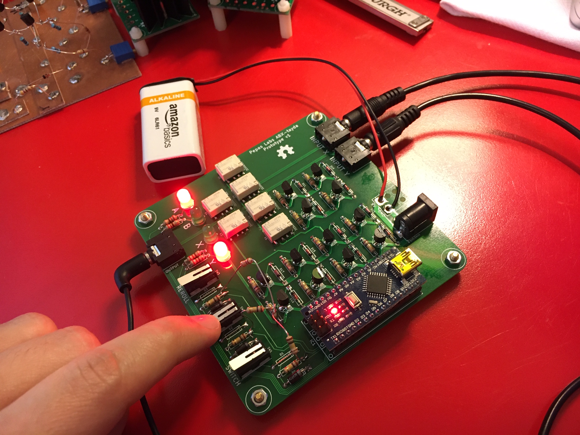
This board design is open source hardware, released under the terms of the MIT license. It requires an ancient version of Kicad (sorry, not sorry 😝). Debian users will need to add a jessie source to install the libpng12 dependency.
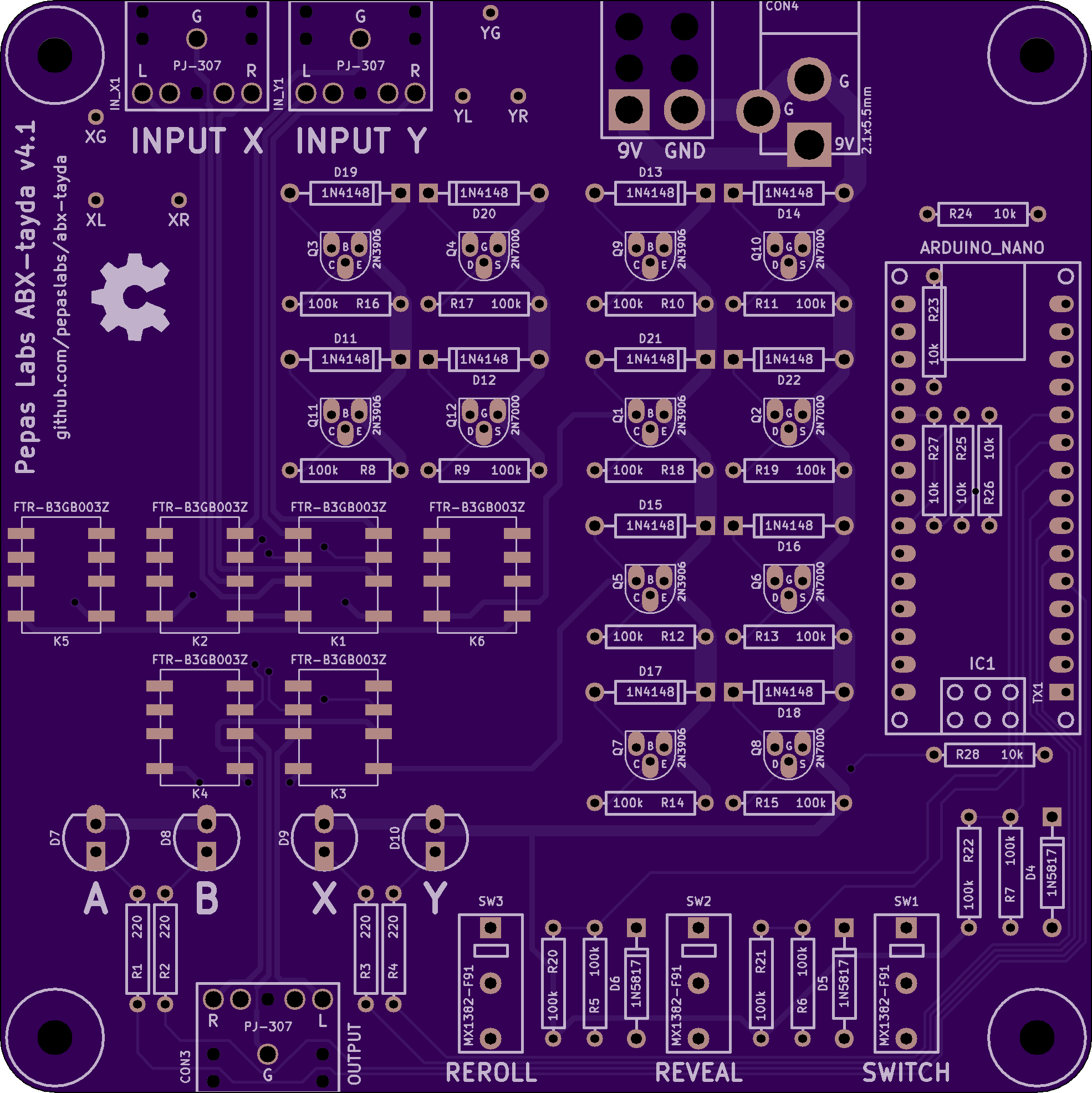
Changes from v4:
Choose one:
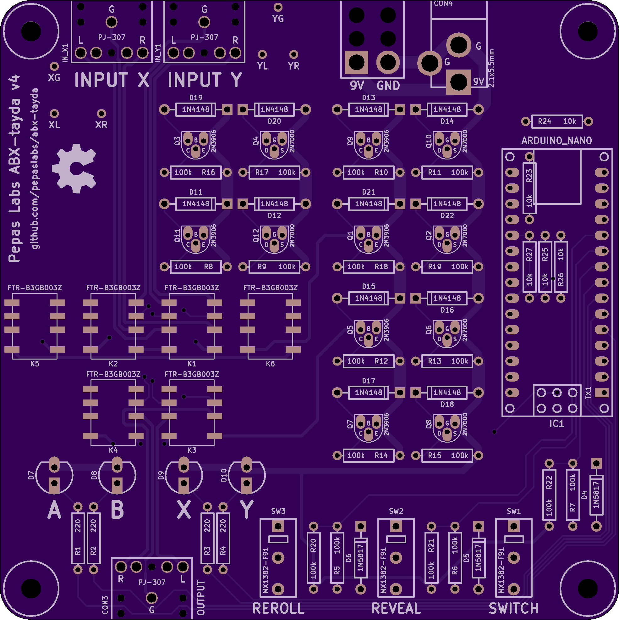
Changes from v3:
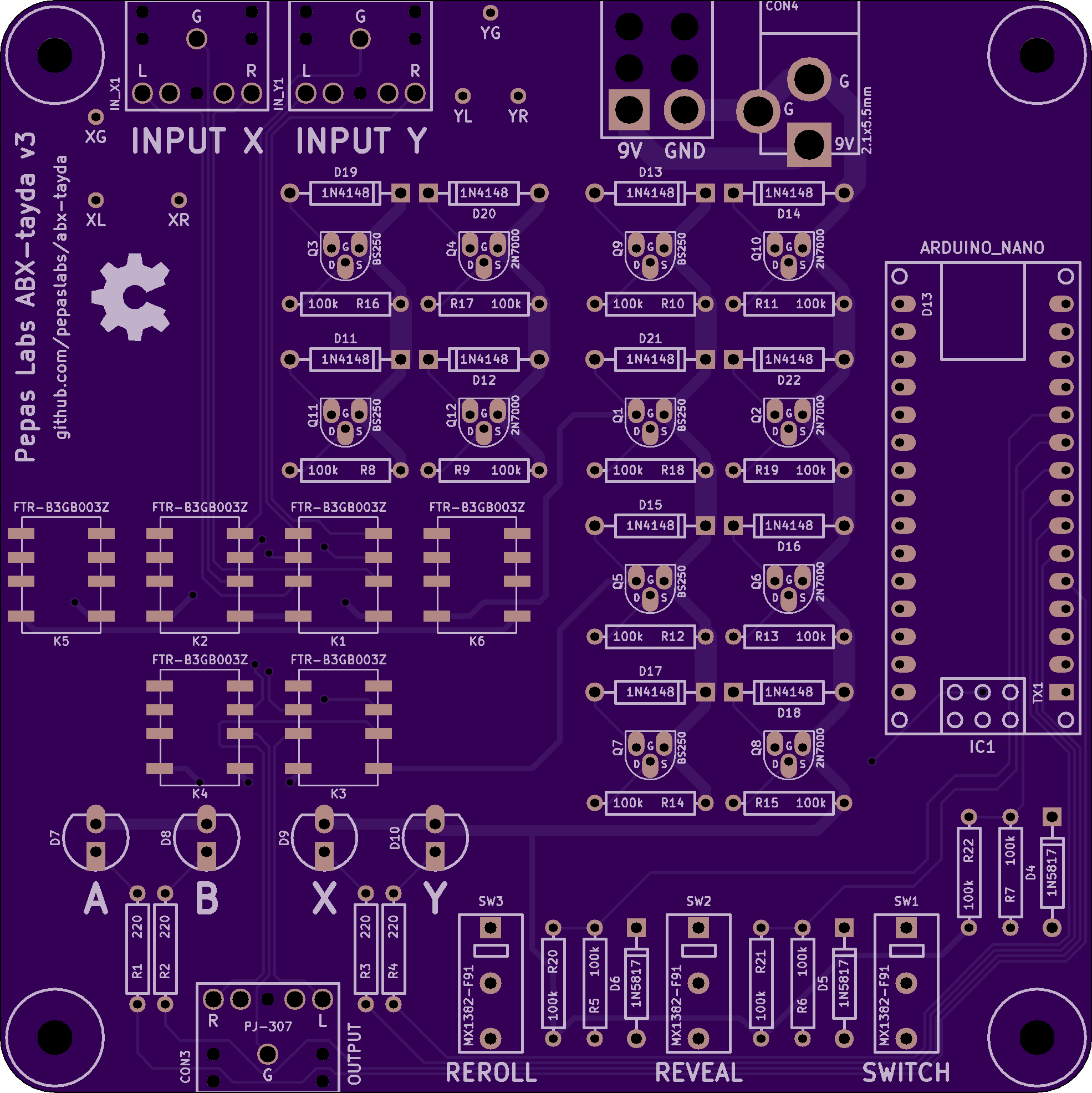
Changes from v2:
This release fixes a couple of bugs from v1:
| Qty | Value | Footprint | References |
|---|---|---|---|
| 18 | 100k | R_AXIAL_0W25_059A_PL | R5, R6, R7, R10, R11, R12, R13, R14, R15, R16, R17, R18, R19, R20, R21, R22 +2 |
| 12 | 1N4148 | DIODE_1A_069A_04_PL | D11, D12, D13, D14, D15, D16, D17, D18, D19, D20, D21, D22 |
| 6 | 10k | R_AXIAL_0W25_059A_PL | R23, R24, R25, R26, R27, R28 |
| 6 | 2N3906 | TO-92_Q_EBC_059Bo_PL | Q1, Q3, Q5, Q7, Q9, Q11 |
| 6 | 2N7000 | TO-92_Q_SGD_059Bo_PL | Q2, Q4, Q6, Q8, Q10, Q12 |
| 6 | FTR-B3GB003Z | FTR-B3G | K1, K2, K3, K4, K5, K6 |
| 4 | 220 | R_AXIAL_0W25_059A_PL | R1, R2, R3, R4 |
| 4 | Val** | hole_M3_NPTH | H***, H***, H***, H*** |
| 3 | 1N5817 | DIODE_1A_069A_04_PL | D4, D5, D6 |
| 3 | PJ-307 | SJ1-3523N | CON3, IN_X1, IN_Y1 |
| 1 | 2.1x5.5mm | BARREL_JACK_21x55 | CON4 |
| 1 | ARDUINO_NANO | ARDUINO_NANO_PL | IC1 |
| 1 | CONN_2X1 | PIGTAIL2 | P1 |
| 1 | LEDA | LED_5MM | D7 |
| 1 | LEDB | LED_5MM | D8 |
| 1 | LEDX | LED_5MM | D9 |
| 1 | LEDY | LED_5MM | D10 |
| 1 | OSHW-logo_silkscreen-front_8mm | OSHW-logo_silkscreen-front_8mm | G*** |
| 1 | REROLL | MX1382-F91 | SW3 |
| 1 | REVEAL | MX1382-F91 | SW2 |
| 1 | SWITCH | MX1382-F91 | SW1 |
| 1 | XG | 1pin_032_058 | P7 |
| 1 | XL | 1pin_032_058 | P5 |
| 1 | XR | 1pin_032_058 | P6 |
| 1 | YG | 1pin_032_058 | P4 |
| 1 | YL | 1pin_032_058 | P2 |
| 1 | YR | 1pin_032_058 | P3 |
It measures 100 × 100 mm and has 2 copper layers, 1.6 mm thick.
85 parts, built around the PJ-307. The full list of its parts is on this page, with links to each part's symbol and footprint where PCBKit's library has them.
From the cellularmitosis/abx-tayda repository on GitHub, at the commit this page was made from: the board is abx.kicad_pcb. PCBKit opens the board in the browser, with nothing to install.
Its repository publishes it under the MIT licence: you may reuse it on that licence's terms (keep the author's notice, and for a copyleft licence share your changes alike).
svirant/DonutDongle
Arduino Nano based hub that connects your digital and analog console switching setup with the RetroTink 4K and/or RetroTink 5x/OSSC for Auto Profile switching

cristianoag/wozblaster
Repository to host source files for the Wozblaster Reloaded


tebl/BulkyMIDI-32
A HW build of the MT32-PI project, allowing you to emulate a Roland MT-32 using a Raspberry Pi. Includes enough additional modules to build a MIDI-mountain as well as adapters for connecting to most things retro.


