2 layers140.5 × 30 mm
Type e
google/mozc-devices
Circuit diagrams and firmware source code for Gboard DIY keyboards
16 parts3kApache-2.0
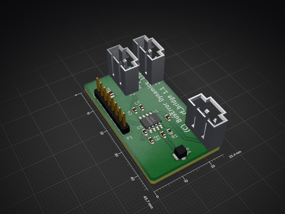
 buserror/rf_bridge39
RF (433Mhz) to MQTT Bridge - with hardware
Rf bridge is an open-source printed circuit board by buserror, from the buserror/rf_bridge repository on GitHub. It is a 2-layer board of 25.4 × 45.7 mm with 16 parts on 17 nets, routed with 50 tracks and 2 vias.
Its parts include 8 capacitors, 5 connectors, 2 resistors and 1 IC. It belongs with the radio and wireless and home automation and IoT boards of this library.
#Hardware: rf_bridge
Version 1.x of the hardware uses very little hardware. You need:
The pcb also has a RF switch to be able to share the antenna. The prototype didn't have that and used 2 17cm pieces of wire, and it worked just fine, so it's not stricly needed. The hardware here is made to be a neater small package with pigtail connector to a 'proper' antenna.
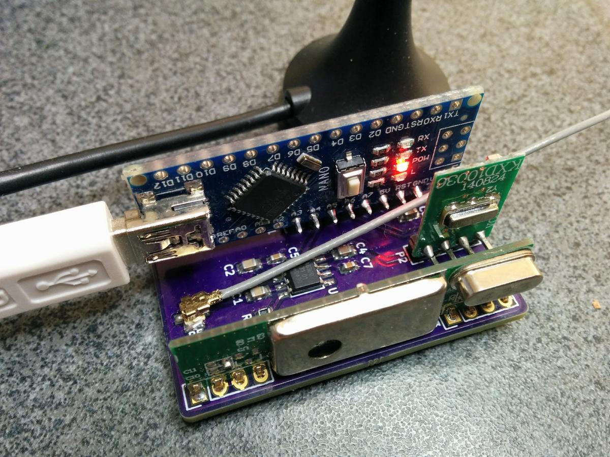
Finished Project
The PCB is very simple, the arduino I picked is a Nano, and it's mounted vertically with the 433 bits, so the result is quite compact.
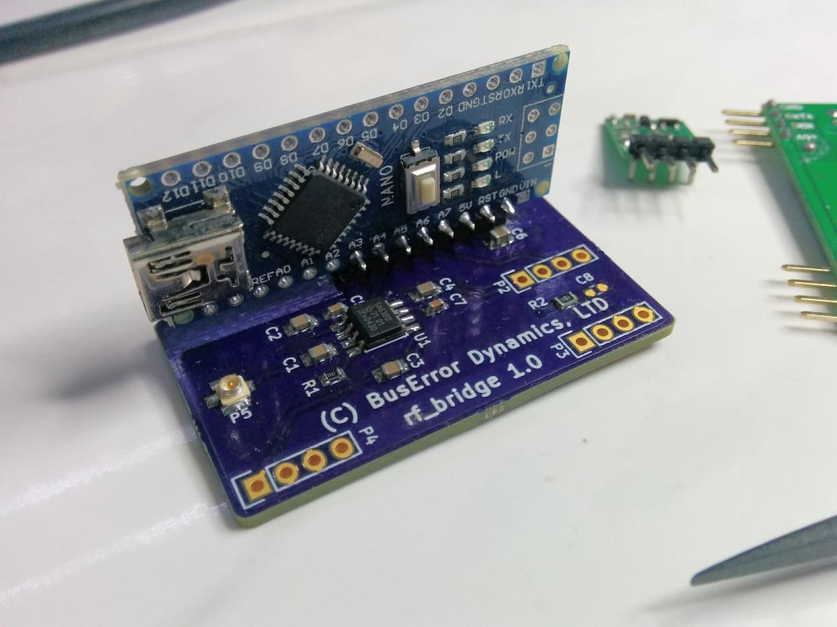
Note the 90 Header is offset by one pin.
##The BOM:
| Ref. | Value | Description |
|---|---|---|
| C1,C2,C3, | ||
| C4,C7 | 10nF | 0603 Caps. |
| C5 | 100nF | 0604 Cap |
| C6 | 4.7uF | 0805 Capacitor (Optional) |
| C8 | 10pF | 0603 Cap (Optional) |
| P1 | Nano | Arduino Nano v3.0. Use 90 headers for mounting. Only use a 8 pins section of them, and the headers are NOT soldered from the first pin, but from the pin marked GND on the Nano, NOT the VIN pin. |
| P2 | RF_TX | Both the TX and the RX comes from eBay. |
| P3,P4 | RF_RX | These are the exact modules I used |
| P5 | U.FR | SMT 'pigtail' antenna Connector Hirose U.FL |
| R1 | 10K | 0603 Pulldown |
| R2 | 100 | 0603 Filtering, use anytime you like here even R0 |
| U1 | SA630 | SOIC8. RF Antenna Switcher. NXP SA630D |
| Qty | Value | Footprint | References |
|---|---|---|---|
| 5 | 10nF | Capacitors_SMD:C_0603 | C1, C2, C3, C4, C7 |
| 1 | 100 | Resistors_SMD:R_0603 | R2 |
| 1 | 100nF | Capacitors_SMD:C_0603 | C5 |
| 1 | 10K | Resistors_SMD:R_0603 | R1 |
| 1 | 10pF | Capacitors_SMD:C_0603 | C8 |
| 1 | 4.7uF | Capacitors_SMD:C_0805 | C6 |
| 1 | BNC | Michels_Library:U.FL-Coax | P5 |
| 1 | CONN_01X08 | Pin_Headers:Pin_Header_Straight_1x08 | P1 |
| 1 | RF_RX1 | Pin_Headers:Pin_Header_Straight_1x04 | P3 |
| 1 | RF_RX2 | Pin_Headers:Pin_Header_Straight_1x04 | P4 |
| 1 | RF_TX | Pin_Headers:Pin_Header_Straight_1x04 | P2 |
| 1 | SA630 | SMD_Packages:SOIC-8-N | U1 |
It measures 25.4 × 45.7 mm and has 2 copper layers, 1.6 mm thick.
16 parts. The full list of its parts is on this page, with links to each part's symbol and footprint where PCBKit's library has them.
From the buserror/rf_bridge repository on GitHub, at the commit this page was made from: the board is kicad/rf_bridge.kicad_pcb. PCBKit opens the board in the browser, with nothing to install.
Its repository states no licence, so its author keeps all rights: ask buserror before reusing the design.
google/mozc-devices
Circuit diagrams and firmware source code for Gboard DIY keyboards

conorpp/u2f-zero
U2F USB token optimized for physical security, affordability, and style

rusefi/rusefi
rusefi - GPL internal combustion engine control unit

VoronDesign/Voron-Hardware
Cool Hardware designed by the Voron Design group

hoglet67/RGBtoHDMI
Bare-metal Raspberry Pi project that provides pixel-perfect sampling of Retro Computer RGB/YUV video and conversion to HDMI

hackclub/OnBoard
💡 Join 1,000 teenagers and make your first PCB with a $100 grant!

