2 layers296.5 × 175.3 mm

 bnparks001/AltusCharger
Multi-Output charger for AltusMetrum batteries.
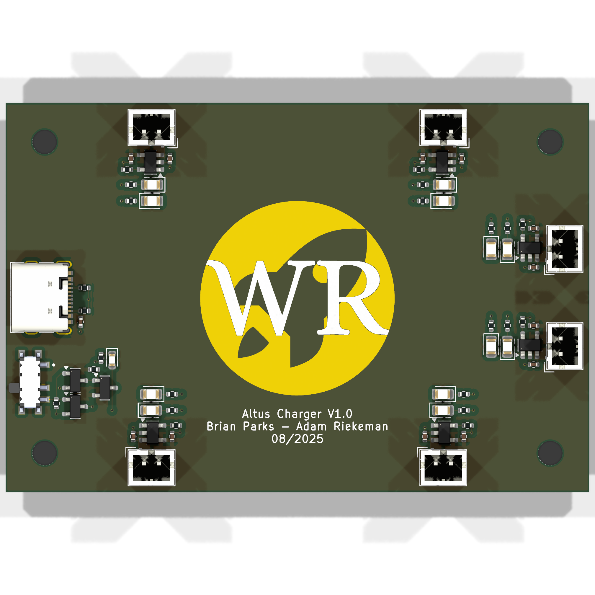
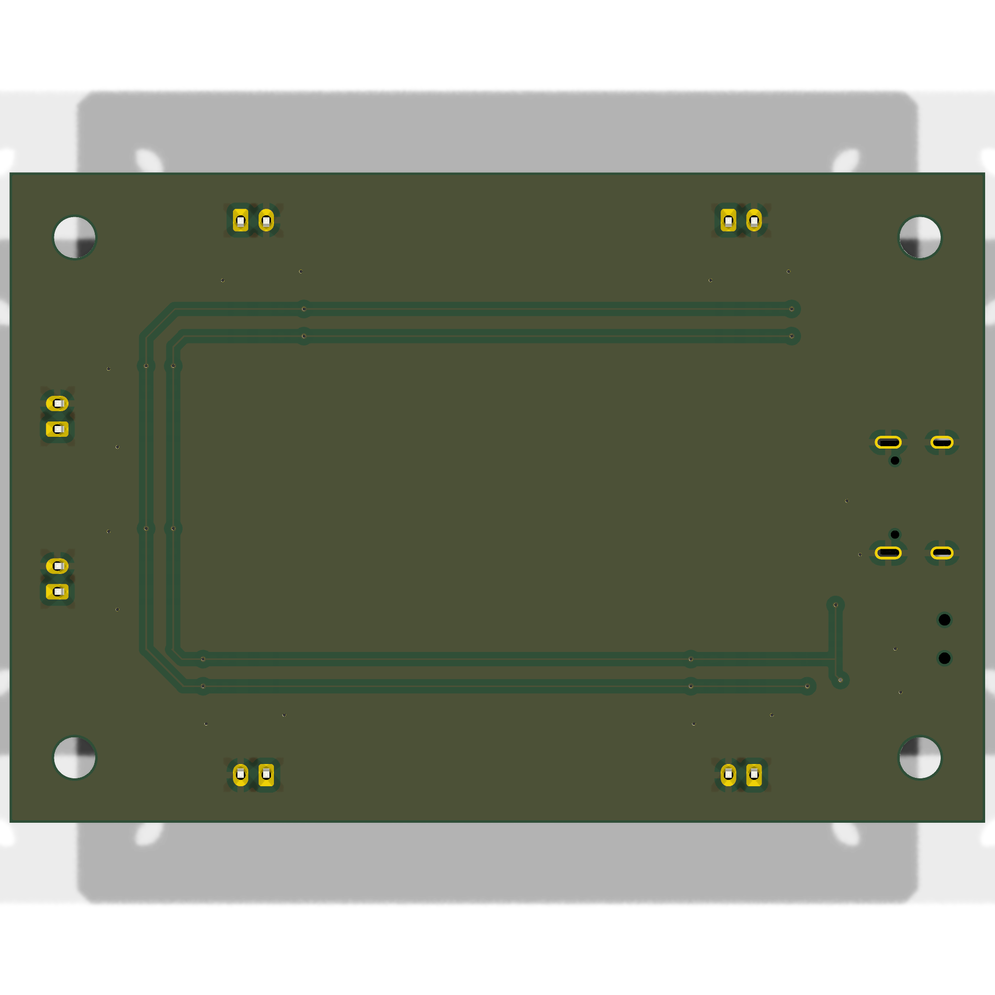
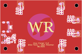
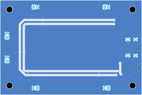
AltusCharger is an open-source printed circuit board by bnparks001, from the bnparks001/AltusCharger repository on GitHub. It is a 2-layer board of 76.2 × 50.8 mm with 71 parts on 46 nets, routed with 125 tracks and 31 vias.
It is built around the KT-0805G, KT-0805R and AO3400A, with the AO3401A, KT-0603R and SSSS811101 among its other parts. Its parts include 23 resistors, 13 capacitors, 13 diodes, 7 connectors and 6 ICs. It belongs with the power boards of this library.


Boards have arrived and passed testing great!
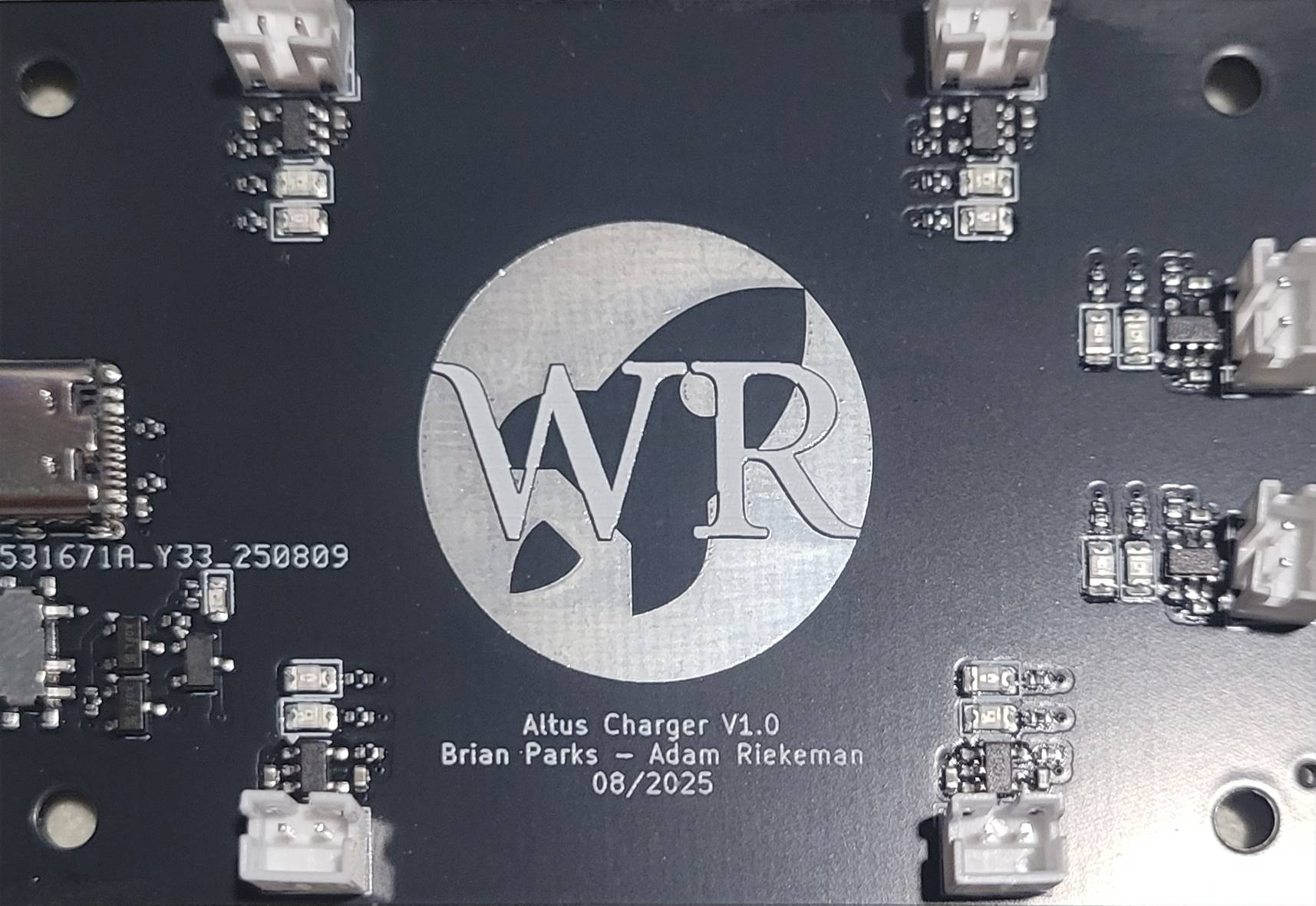
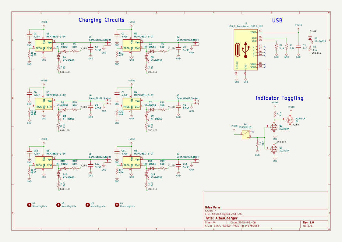
This project is designed to support charging of 6 Altus Metrum batteries over a 5V 2A USB-C connection using the same battery charging circuit as the Telemega. Therefore, the RProg resistor selection was set to 3.3k to charge each battery at ~300mA. For context, the Telemega integrated charger is configured to charge at ~342mA. This results in ~13% slower charging per battery. However, with the benefit of charging multiple batteries at once this quickly makes up the difference. This project also includes a switch to turn off the LED indicators for overnight charging.
The root level schematic shows the overall blocking of the hardware design.
| Qty | Value | Footprint | References |
|---|---|---|---|
| 12 | 4.7uF | Capacitor_SMD:C_0402_1005Metric | C1, C2, C4, C5, C6, C7, C8, C9, C10, C11, C12, C13 |
| 8 | 1k | Resistor_SMD:R_0402_1005Metric | R8, R9, R14, R15, R16, R17, R22, R23 |
| 7 | 510 | Resistor_SMD:R_0402_1005Metric | R3, R4, R5, R10, R11, R18, R19 |
| 6 | 3.3k | Resistor_SMD:R_0402_1005Metric | R6, R7, R12, R13, R20, R21 |
| 6 | Conn_01x02_Socket | Connector_JST:JST_PH_B2B-PH-K_1x02_P2.00mm_Vertical | J1, J2, J4, J5, J6, J7 |
| 6 | KT-0805G | LED_SMD:LED_0805_2012Metric | D4, D5, D8, D9, D12, D13 |
| 6 | KT-0805R | LED_SMD:LED_0805_2012Metric | D2, D3, D6, D7, D10, D11 |
| 6 | MCP73831-2-OT | Package_TO_SOT_SMD:SOT-23-5 | U1, U2, U3, U4, U5, U6 |
| 4 | MountingHole | MountingHole:MountingHole_3.2mm_M3 | H1, H2, H3, H4 |
| 2 | 5.1k | Resistor_SMD:R_0402_1005Metric | R1, R2 |
| 2 | AO3400A | Package_TO_SOT_SMD:SOT-23 | Q2, Q3 |
| 1 | 1uF | Capacitor_SMD:C_0402_1005Metric | C3 |
| 1 | AO3401A | Package_TO_SOT_SMD:SOT-23 | Q1 |
| 1 | KT-0603R | LED_SMD:LED_0603_1608Metric | D1 |
| 1 | LOGO | AltusCharger-Lib:WR_Logo | G*** |
| 1 | SSSS811101 | AltusCharger-Lib:SW_SSSS811101 | SW1 |
| 1 | USB_C_Receptacle_USB2.0_16P | Connector_USB:USB_C_Receptacle_G-Switch_GT-USB-7010ASV | J3 |

anhldptit2610/dalws
This project is my attempt to learn about microcontroller and PCB design. Now I realize that making a full, complete electronic project is super hard.

Kilan777/HomeDeck
Jarvis HomeDeck: a Raspberry Pi CM4 carrier board and voice-assistant software for a 7-inch smart display (KiCad hardware, generated from Python, plus the Python/JS assistant)


totaldesaster/SimpleFOC-Serial-Driver
Advanced dual BLDC driver based on the RP2350 and DRV8323S ICs, designed to be controlled from a trajectory controller over RS-485, RS-422 or TTL UART. Features a compact high power design with two stacked PCBs.


ackom-a-o/stm32f446-development-board
Custom STM32F446ZET6 development board in KiCad. Prototype hardware, design review and validation log; hardware testing pending.

Kraad25/USB-C-Advanced-Power-Supply
USB-C PD trigger board (CH224A) — KiCad schematic and PCB layout, selectable 5/9/12/20/28V output
It measures 76.2 × 50.8 mm and has 2 copper layers, 1.61 mm thick.
71 parts, built around the KT-0805G, KT-0805R, AO3400A and AO3401A. The full list of its parts is on this page, with links to each part's symbol and footprint where PCBKit's library has them.
From the bnparks001/AltusCharger repository on GitHub, at the commit this page was made from: the board is Hardware/AltusCharger/kicad/AltusCharger.kicad_pcb and its schematic Hardware/AltusCharger/kicad/AltusCharger.kicad_sch. PCBKit opens the board in the browser, with nothing to install.
Its repository states no licence, so its author keeps all rights: ask bnparks001 before reusing the design.