
4 layers58 × 70 mm
Probelab
enkhbold470/kicad-projects
Five KiCad 10 boards (4- and 6-layer): ESP32-S3 industrial gateway, USB-C PD bench supply, RP2040 logic analyzer, FOC motor controller, iCE40 FPGA board.
88 partsCERN-OHL-S-2.0

Custom STM32F446ZET6 development board in KiCad. Prototype hardware, design review and validation log; hardware testing pending.
Stm32 is an open-source printed circuit board by ackom-a-o, from the ackom-a-o/stm32f446-development-board repository on GitHub. It is a 4-layer board of 80 × 70 mm with 69 parts on 135 nets, routed with 1,178 tracks and 226 vias.
It is built around the STM32F446ZET6, USBLC6-2SC6 and CC0805KRX7R9BB104, with the CL21B105KBFNNNE, B3F-1000 and CL21B225KAFVPJE among its other parts. Its parts include 29 capacitors, 15 resistors, 8 connectors, 5 diodes and 4 ICs. It belongs with the microcontroller boards boards and the STM32 boards of this library.


A custom, USB-powered development board for sensor and control experiments, built around the STM32F446ZET6. This project follows an embedded hardware design from component selection and PCB layout through assembly preparation, firmware and bench validation.
Current milestone: prototype fabrication preparation. The corrected design, fabrication exports and assembly data are published below. Hardware is not yet bench-tested; final assembler production-file approval and physical validation remain open.
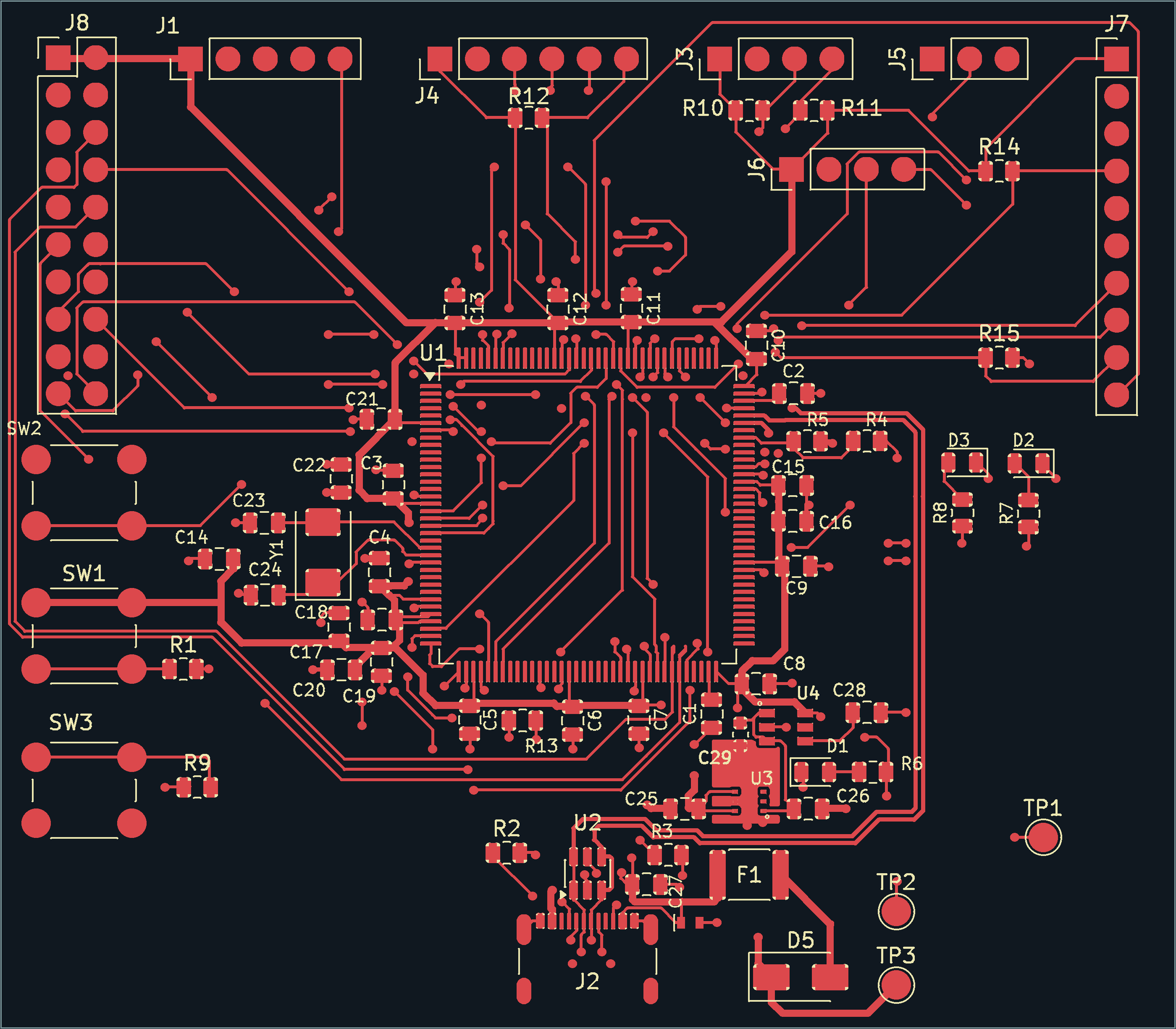
Composed from the current fabrication Gerbers. Top copper and silkscreen only; drill holes are not depicted. This is a design view, not an assembled-board photograph.
Schematic PDF · Engineering review · Validation evidence · Manufacturing package · First power-up
| Area | Implementation |
|---|---|
| MCU | STM32F446ZET6, Arm Cortex-M4, LQFP-144 |
| PCB | 80 × 70 mm, four copper layers, nominal 1.6 mm |
| Power | USB 5 V → protection → TPS7A2533 regulator → TPS22918 load switch → 3.3 V |
| Connectivity | USB 2.0 full-speed device, SPI, I²C, UART, analog and GPIO headers |
| CAN expansion | Classical CAN 2.0B on J7: PD0/RX and PD1/TX; requires an external 3.3 V logic-compatible transceiver |
| Debug | External SWD probe through a custom five-pin header |
| Clock | 8 MHz crystal |
| User controls | Three pushbuttons and three indicator LEDs |
USB host operation, USB Power Delivery and motor-power delivery are outside the current scope. The load switch controls rail startup; it is not a programmable current limiter.
flowchart LR
    USB[USB-C 5 V] --> Protection[Fuse and series diode]
    Protection --> LDO[TPS7A2533 regulator]
    LDO --> Switch[TPS22918 load switch]
    Switch --> Rail[3.3 V MCU and headers]
    Host[USB host data] <--> ESD[USBLC6 protection]
    ESD <--> MCU[STM32F446]
    Probe[External SWD probe] <--> MCU
    MCU <--> IO[SPI / I2C / UART / GPIO]
    MCU <--> CANHeader[J7: PD0 RX / PD1 TX]
    CANHeader <--> Transceiver[External CAN transceiver - required]
    Transceiver <--> CANBus[CANH / CANL bus]
CAN uses the MCU's existing CAN1 controller through J7 pin 3 (PD0/CAN1_RX) and pin 4 (PD1/CAN1_TX), configured as AF9. The transceiver and bus termination are external to this PCB. This is Classical CAN, not CAN FD, and firmware/link testing is pending.
The layout was reviewed against MCU and power-component datasheets, ST's USB hardware guidance and published signal-integrity advice. Checks covered electrical connectivity, local bypassing, ground return paths, USB geometry, reset/crystal placement, sourcing, footprint fit and assembly orientation. The engineering review records the reasoning, corrections, references and remaining limits.
Peer feedback and AI-assisted checks supported these iterations. Bench measurements will be reported separately from calculations and software checks.
Recorded checks on 22 October 2026 report 0 ERC issues, 0 DRC violations, 0 unconnected items and 0 schematic parity issues, with no ignored checks or current exclusions. The published inventory contains 66 assembly references, plus three PCB test points. Validation evidence links the source hashes, reports and geometric checks; these do not establish measured hardware performance.
The fabricator has confirmed the nominal JLC04161H-7628 construction used as the design basis. Next: approve final production files and bring up the prototype. The bring-up checklist starts with inspection, shorts and power rails, then SWD/reset, clock startup, GPIO and USB. Every physical test in the test log remains not tested. Firmware will be added when implementation begins.
Open stm32.kicad_pro in KiCad 10, with its standard libraries installed.
The four-sheet schematic separates power, USB/debug/clock, peripheral interfaces and expansion. The MCU uses eight symbol units so that supply pins and GPIO ports can be reviewed separately. Named signals connect sheets; pin numbers retain their physical package mapping.
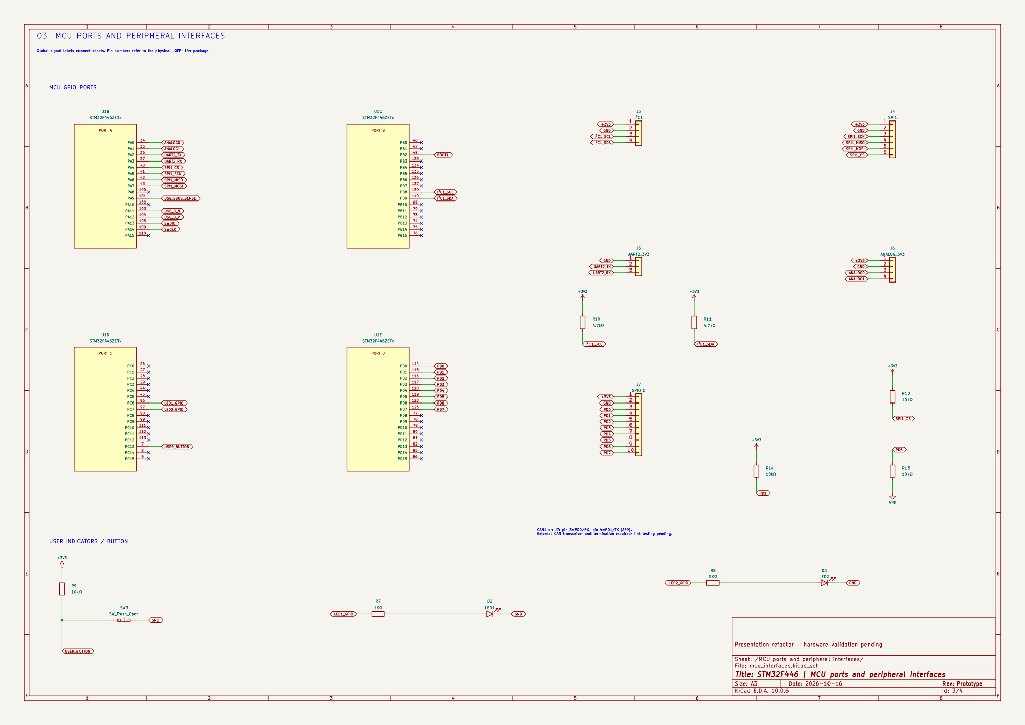
Sheet 3 of 4. The earlier readability refactor preserved its then-current 68 physical references and all 135 nets; historical comparison evidence records unchanged PCB geometry for that refactor. The subsequent C29 addition brings the current physical-reference count to 69.
| Files | Purpose |
|---|---|
stm32.kicad_sch | Root sheet: power path and MCU supplies |
usb_debug_clock.kicad_sch | USB, clock, reset, boot and SWD |
mcu_interfaces.kicad_sch, gpio_expansion.kicad_sch | MCU ports, peripheral headers and expansion |
stm32.kicad_pcb | Routed four-layer PCB |
stm32.kicad_dru | Project design rules |
STM32_Custom.pretty, STM32_Power.kicad_sym, STM32_MCU.kicad_sym | Local footprints, power symbols and split MCU symbol |
fp-lib-table, sym-lib-table | Project-relative library configuration |
docs/ | Schematic export, design decisions, part inventory and validation evidence |
Local libraries are included. The empty Library.pretty directory is retained for the existing project library table. The prototype-r3 package contains Gerbers/drills, BOM, supplier-adjusted placement data and file hashes. It is an unvalidated prototype package, not a production-qualified release. Placement rotations are supplier-specific; another assembler must check its own conventions.
STM32F446 datasheet · TPS7A25 datasheet · TPS22918 datasheet
A project hardware/documentation license has not yet been selected. No explicit open-source license is currently granted. Third-party assets remain subject to their respective licenses.
| Qty | Value | Footprint | References |
|---|---|---|---|
| 17 | 100nF | Capacitor_SMD:C_0805_2012Metric | C3, C4, C5, C6, C7, C8, C10, C11, C12, C13, C15, C17, C19, C21, C22, C27 +1 |
| 6 | 10kΩ | Resistor_SMD:R_0805_2012Metric | R1, R9, R12, R13, R14, R15 |
| 3 | 1KΩ | Resistor_SMD:R_0805_2012Metric | R6, R7, R8 |
| 3 | 1µF | Capacitor_SMD:C_0805_2012Metric | C16, C18, C20 |
| 3 | SW_Push_Open | Button_Switch_THT:SW_PUSH_6mm_H4.3mm | SW1, SW2, SW3 |
| 2 | 2.2uF | Capacitor_SMD:C_0805_2012Metric | C1, C2 |
| 2 | 22pF C0G | Capacitor_SMD:C_0805_2012Metric | C23, C24 |
| 2 | 4.7kΩ | Resistor_SMD:R_0805_2012Metric | R10, R11 |
| 2 | 5.1kΩ 1% | Resistor_SMD:R_0805_2012Metric | R2, R3 |
| 1 | 1µF | Capacitor_SMD:C_0603_1608Metric | C29 |
| 1 | 2.2uF 25V X7R | Capacitor_SMD:C_0805_2012Metric | C26 |
| 1 | 2.2uF25VX7R | Capacitor_SMD:C_0805_2012Metric | C25 |
| 1 | 33kΩ,1% | Resistor_SMD:R_0805_2012Metric | R4 |
| 1 | 3V3 | TestPoint:TestPoint_Pad_D2.0mm | TP2 |
| 1 | 4.7nF | Capacitor_SMD:C_0805_2012Metric | C28 |
| 1 | 4.7uF | Capacitor_SMD:C_0805_2012Metric | C14 |
| 1 | 500mA | Fuse:Fuse_1812_4532Metric | F1 |
| 1 | 82kΩ,1% | Resistor_SMD:R_0805_2012Metric | R5 |
| 1 | 8MHz | Crystal:Crystal_SMD_Abracon_ABM3-2Pin_5.0x3.2mm | Y1 |
| 1 | ANALOG_3V3 | Connector_PinHeader_2.54mm:PinHeader_1x04_P2.54mm_Vertical | J6 |
| 1 | ESDA7P120-1U1M | STM32_Custom:ESDA7P60-1U1M | D4 |
| 1 | EXPANSION_3V3 | Connector_PinHeader_2.54mm:PinHeader_2x10_P2.54mm_Vertical | J8 |
| 1 | GND | TestPoint:TestPoint_Pad_D2.0mm | TP1 |
| 1 | GPIO_D | Connector_PinHeader_2.54mm:PinHeader_1x10_P2.54mm_Vertical | J7 |
| 1 | Green | LED_SMD:LED_0805_2012Metric | D1 |
| 1 | I²C1 | Connector_PinHeader_2.54mm:PinHeader_1x04_P2.54mm_Vertical | J3 |
| 1 | LED1 | LED_SMD:LED_0805_2012Metric | D2 |
| 1 | LED2 | LED_SMD:LED_0805_2012Metric | D3 |
| 1 | SPI1 | Connector_PinHeader_2.54mm:PinHeader_1x06_P2.54mm_Vertical | J4 |
| 1 | SS14 | Diode_SMD:D_SMA | D5 |
| 1 | STM32F446ZETx | Package_QFP:LQFP-144_20x20mm_P0.5mm | U1 |
| 1 | SWD | Connector_PinHeader_2.54mm:PinHeader_1x05_P2.54mm_Vertical | J1 |
| 1 | TPS22918DBVR | STM32_Custom:TPS22918_DBV0006A | U4 |
| 1 | TPS7A2533DRVR | STM32_Custom:TPS7A25_DRV0006A | U3 |
| 1 | UART2_3V3 | Connector_PinHeader_2.54mm:PinHeader_1x03_P2.54mm_Vertical | J5 |
| 1 | USBLC6-2SC6 | Package_TO_SOT_SMD:SOT-23-6 | U2 |
| 1 | USB_5V | TestPoint:TestPoint_Pad_D2.0mm | TP3 |
| 1 | USB_C_Receptacle_USB2.0_16P | STM32_Custom:USB_C_Receptacle_USB4105_JLC | J2 |
enkhbold470/kicad-projects
Five KiCad 10 boards (4- and 6-layer): ESP32-S3 industrial gateway, USB-C PD bench supply, RP2040 logic analyzer, FOC motor controller, iCE40 FPGA board.

swittlich/prjfreeman
Open-source flow (yosys + nextpnr) and bitstream documentation for the XC2064, the first FPGA


psobot/musicboy
A high-quality audio playback cartridge for Nintendo® Game Boy® and Game Boy Color®.


PedroBMedeiros/PolySaber
Firmware for Cal Poly Senior Project - PolySaber a Custom PCB Soundboard


It measures 80 × 70 mm and has 4 copper layers, 1.6 mm thick.
69 parts, built around the STM32F446ZET6, USBLC6-2SC6, CC0805KRX7R9BB104 and CL21B105KBFNNNE. The full list of its parts is on this page, with links to each part's symbol and footprint where PCBKit's library has them.
From the ackom-a-o/stm32f446-development-board repository on GitHub, at the commit this page was made from: the board is stm32.kicad_pcb and its schematic gpio_expansion.kicad_sch. PCBKit opens the board in the browser, with nothing to install.
Its repository states no licence, so its author keeps all rights: ask ackom-a-o before reusing the design.