
2 layers99.1 × 99.1 mm
Vent
pandemiaplan/OP-Vent
A Simple, Open-Source Ventilator using a Proportional Solenoid Valve
113 parts5
 bitraf/toollock
Each lock has a key with a matching key pattern. The key is physically attached to the tool using a wire. An optical sensor detects that the right key is used.
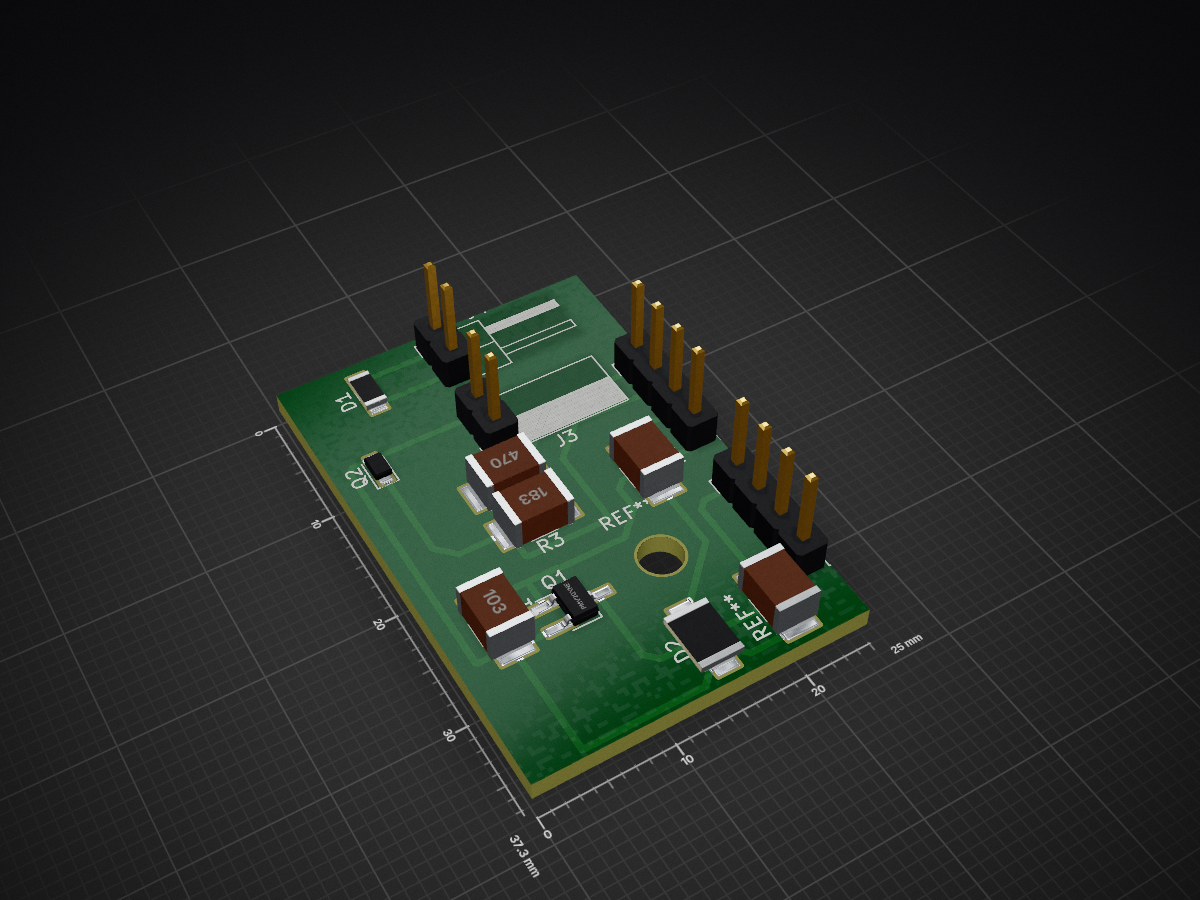
TheLock schematics is an open-source printed circuit board by bitraf, from the bitraf/toollock repository on GitHub. It is a 2-layer board of 25 × 37.3 mm with 14 parts on 11 nets, routed with 65 tracks and 2 vias.
It is built around the PMV20XNER. Its parts include 4 resistors, 4 connectors, 2 diodes and 2 transistors. It belongs with the home automation and IoT boards of this library.
Electronic lock connected via wireless (Wi-Fi) and MQTT using MsgFlo. The lock is intended to enforce 'checking out' and 'checking in' portable tools in a shared workshop environment.
It makes it possible to:
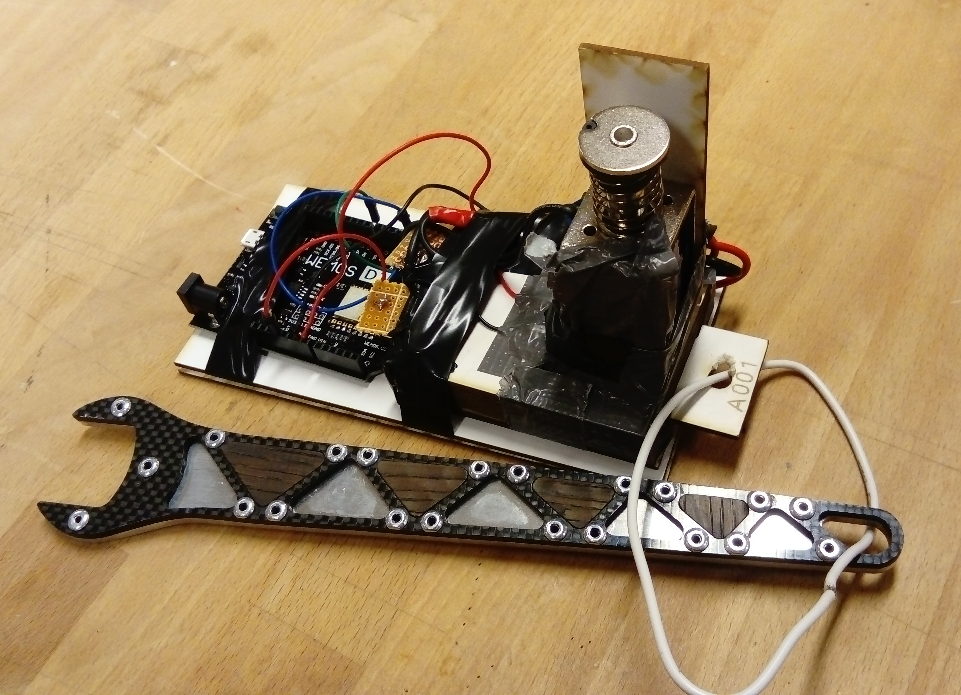
Each lock has a key with a matching key pattern. The key is physically attached to the tool using a wire. An optical sensor detects that the right key is used. IR leds normally light through, only a matching key will fully block light.
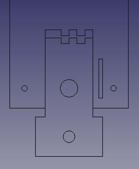
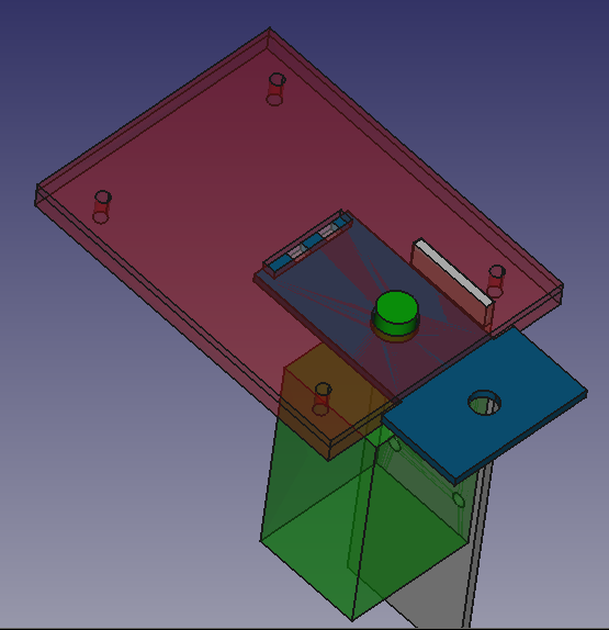
The key and lock can be CNC-milled, lasercut or 3d-printed.
Proof of concept
https://wiki.wemos.cc/products:d1:d1_mini https://github.com/esp8266/esp8266-wiki/wiki/Pin-definition
Config.h defining parameters WIFI_SSID and WIFI_PASSWORDv1.0: First fabricated version
MIT

Developed in KiCAD.

Developed in FreeCAD.
SIG: gnd+in PWR: 12v+gnd OUT: 12v+out
IN GND 12v 12v OUT
| Qty | Value | Footprint | References |
|---|---|---|---|
| 1 | 10k | Resistors_SMD:R_1210_HandSoldering | R1 |
| 1 | 18k | Resistors_SMD:R_1210_HandSoldering | R3 |
| 1 | 47 | Resistors_SMD:R_1210_HandSoldering | R2 |
| 1 | CONN_IRBOARD | Socket_Strips:Socket_Strip_Angled_1x02_Pitch2.54mm | J3 |
| 1 | CONN_IRLED | Pin_Headers:Pin_Header_Angled_1x02_Pitch2.54mm | J4 |
| 1 | CONN_POWER | Pin_Headers:Pin_Header_Angled_1x04_Pitch2.54mm | J2 |
| 1 | CONN_SIGNAL | Pin_Headers:Pin_Header_Angled_1x04_Pitch2.54mm | J1 |
| 1 | IR LED | LEDs:LED_0805_HandSoldering | D1 |
| 1 | IR PHOTOTRANS | Diodes_SMD:D_0805 | Q2 |
| 1 | LED | LEDs:LED_1206_HandSoldering | D2 |
| 1 | PMV20XNE | TO_SOT_Packages_SMD:SOT-23W_Handsoldering | Q1 |
| 1 | R | Resistors_SMD:R_1210_HandSoldering | R4 |
The 12 most common of 14 parts.
It measures 25 × 37.3 mm and has 2 copper layers, 1.6 mm thick.
14 parts, built around the PMV20XNER. The full list of its parts is on this page, with links to each part's symbol and footprint where PCBKit's library has them.
From the bitraf/toollock repository on GitHub, at the commit this page was made from: the board is TheLock-schematics/TheLock-schematics.kicad_pcb. PCBKit opens the board in the browser, with nothing to install.
Its repository states no licence, so its author keeps all rights: ask bitraf before reusing the design.
pandemiaplan/OP-Vent
A Simple, Open-Source Ventilator using a Proportional Solenoid Valve

UCSIG/attiny85_time_switch
Low-power time switch using the ATtiny85 microcontroller.


PTR-projects/PTR_arecorder
A compact, high-g flight data recorder designed specifically for model and amateur rocketry. The Arecorder logs 3-axis acceleration and orientation data to an SD card during launch, ascent, apogee, and recovery.

google/mozc-devices
Circuit diagrams and firmware source code for Gboard DIY keyboards


hackclub/OnBoard
💡 Join 1,000 teenagers and make your first PCB with a $100 grant!
