4 layers60 × 60 mm
AUXSPACE core pcb
AUXSPACEeV/AUX-Core
Core/Master PCB for the Auxspace Avionics stack
83 partsCERN-OHL-P-2.0

 AUXSPACEeV/microMETER
Minimal Flightcomputer
Main PCB is an open-source printed circuit board by AUXSPACEeV, from the AUXSPACEeV/microMETER repository on GitHub, published under the CERN-OHL-P-2.0 licence. It is a 4-layer board of 32 × 66 mm with 90 parts on 72 nets, routed with 559 tracks and 79 vias.
It is built around the ESP32-S3-WROOM-1-N8, TCAN334D and BMP581, with the TPS7B8601QDDARQ1, 2N7002K and DMP3099L among its other parts. Its parts include 32 resistors, 23 capacitors, 8 transistors, 6 connectors and 5 ICs. It belongs with the ESP32 boards of this library.


µMETERMinimal flight computer on a 4-layer PCB with an ESP32-S3-WROOM-1.
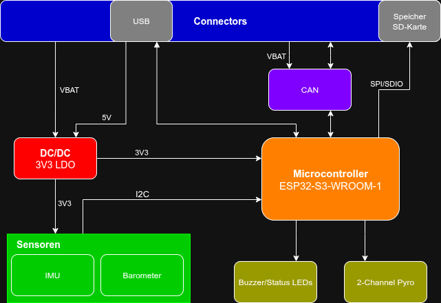
µMETER provides two separated Pyro Channels. To prevent voltage drops from the ignition the battery is decoupled via two 680µF capacitors. The capacitors are charging/discharging when the ARM-Signal is enabled/disabled for about 2.8 sec. To be sure that the capacitors are fully charged, wait at least 3 sec between the first and second ignition. Alternatively, you can measure the voltage across the electrolytic capacitors on GPIO14.
The ESP is programmed via the UART or USB-C connection. To enter download mode, press and hold BOOTSEL at startup.
You can find STEP files in 6_Export-Fertigungsdaten.
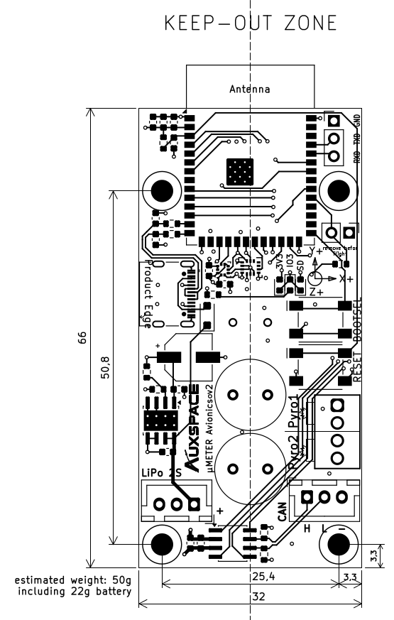
The board is powered by a 2S LiPo battery with 500mAh each.
| Qty | Value | Footprint | References |
|---|---|---|---|
| 16 | 4,7k | Resistor_SMD:R_0603_1608Metric | R2, R5, R7, R8, R9, R10, R11, R16, R19, R20, R21, R22, R24, R25, R26, R32 |
| 13 | 100nF | Capacitor_SMD:C_0603_1608Metric | C1, C3, C4, C5, C6, C8, C9, C11, C13, C14, C16, C25, C39 |
| 5 | 2N7002K | Package_TO_SOT_SMD:SOT-23 | Q1, Q4, Q5, Q6, Q8 |
| 4 | MountingHole_Pad | MountingHole:MountingHole_3.2mm_M3_DIN965 | H1, H2, H3, H4 |
| 3 | 10µF | Capacitor_SMD:C_0603_1608Metric | C7, C15, C26 |
| 3 | 390R | Resistor_SMD:R_0603_1608Metric | R13, R14, R23 |
| 3 | DMP3099L | Package_TO_SOT_SMD:SOT-23 | Q2, Q3, Q7 |
| 3 | grün | LED_SMD:LED_0603_1608Metric | D1, D2, D3 |
| 2 | 10nF | Capacitor_SMD:C_0603_1608Metric | C19, C20 |
| 2 | 11k | Resistor_SMD:R_0603_1608Metric | R4, R15 |
| 2 | 1µF | Capacitor_SMD:C_0603_1608Metric | C10, C17 |
| 2 | 22R | Resistor_SMD:R_0603_1608Metric | R27, R28 |
| 2 | 330R | Inductor_SMD:L_1206_3216Metric | R12, R18 |
| 2 | 430481025816 | AUXSPACE:SW_Wurth_WS-TASV_430481025816 | SW2, SW3 |
| 2 | 5,1k | Resistor_SMD:R_0603_1608Metric | R29, R30 |
| 2 | 62R | Resistor_SMD:R_0603_1608Metric | R1, R17 |
| 2 | 680µF | Capacitor_THT:C_Radial_D10.0mm_H12.5mm_P5.00mm | C23, C24 |
| 2 | 8,2k | Resistor_SMD:R_0603_1608Metric | R3, R31 |
| 2 | JST XH 3p | Connector_JST:JST_XH_B3B-XH-A_1x03_P2.50mm_Vertical | J3, J4 |
| 2 | LOGO | LOGO | G***, G*** |
| 2 | SS24FL | Diode_SMD:D_SOD-123F | D4, D5 |
| 1 | 150 µF | AUXSPACE:CP_Wurth_WCAP-ASLL-D6.3L5.5 | C2 |
| 1 | 2,7k | Resistor_SMD:R_0603_1608Metric | R6 |
| 1 | 691210910004 | Altium_WR-TBL_Rising Cage Clamp (rev25a):691210910004 | J5 |
| 1 | 693072010801 | Connector_Card:microSD_HC_Wuerth_693072010801 | J1 |
| 1 | BMP581 | Package_LGA:ST_HLGA-10_2x2mm_P0.5mm_LayoutBorder3x2y | U8 |
| 1 | ESP32-S3-WROOM-1 | RF_Module:ESP32-S3-WROOM-1 | U4 |
| 1 | LOGO | 1KiCadLib:LT4mm | G*** |
| 1 | LSM6DSO32XTR | AUXSPACE:LGA_O32XTR_STM | U3 |
| 1 | PinHeader 2,54mm 2p | Connector_PinHeader_2.54mm:PinHeader_1x02_P2.54mm_Vertical | JP1 |
| 1 | PinHeader 2,54mm 3p | Connector_PinHeader_2.54mm:PinHeader_1x03_P2.54mm_Vertical | J2 |
| 1 | TCAN334 | Package_SO:SOIC-8_3.9x4.9mm_P1.27mm | U1 |
| 1 | TPS7B8601QDDARQ1 | Package_SO:Texas_R-PDSO-G8_EP2.95x4.9mm_Mask2.4x3.1mm_ThermalVias | U2 |
| 1 | USB_C_Plug_USB2.0 | AUXSPACE:J_Wurth_WR-USB_629722000214 | P1 |
| 1 | WST-0904T | AUXSPACE:Buzzer_WST-0906T | BZ1 |
It measures 32 × 66 mm and has 4 copper layers, 1.58 mm thick.
90 parts, built around the ESP32-S3-WROOM-1-N8, TCAN334D, BMP581 and TPS7B8601QDDARQ1. The full list of its parts is on this page, with links to each part's symbol and footprint where PCBKit's library has them.
From the AUXSPACEeV/microMETER repository on GitHub, at the commit this page was made from: the board is 3_Elektronik/KiCad/Main_PCB.kicad_pcb and its schematic 3_Elektronik/KiCad/Main_PCB.kicad_sch. PCBKit opens the board in the browser, with nothing to install.
Its repository publishes it under the CERN-OHL-P-2.0 licence: you may reuse it on that licence's terms (keep the author's notice, and for a copyleft licence share your changes alike).
AUXSPACEeV/AUX-Core
Core/Master PCB for the Auxspace Avionics stack

pcailliatte/MowerBoard
MowerBoard est une unité de contrôle électronique (ECU) alternative, robuste et 100% open-source pour tracteurs tondeuses autoportées thermiques.


notaroomba/ledify
A super small addressable LED controller with USB-C PD up to 100W, a switchable 5V/12V output and Bluetooth!


jason-watkins/nixie-clock
USB-C powered nixie tube clock. Four IN-12B digits, two INS-1 colon lamps, K155ID1 BCD decoder/drivers.

