
4 layers156.8 × 127 mm
Payload PCB v3.1
team-mountaineers-urc-2023/electronics
Block diagrams, schematics, and PCB files related to the electronics subteam
197 parts2BSD-3-Clause

 austindriggs/urc-payload-pcb
All-purpose control and interface board designed to manage mission-critical sensors and electronics for University Rover Challenge at WVU.
Payload pcb is an open-source printed circuit board by austindriggs, from the austindriggs/urc-payload-pcb repository on GitHub, published under the MIT licence. It is a 4-layer board of 127 × 76.2 mm with 114 parts on 105 nets, routed with 742 tracks and 322 vias.
It is built around the MCP2562-H/P, SC0915 and LTC2990IMS#TRPBF, with the MCP2200-I/SS, MCP2515-I and MIC94093YC6-TR among its other parts. Its parts include 24 resistors, 23 connectors, 22 capacitors, 9 ICs and 8 diodes. It belongs with the sensors and measurement and interfaces and adapters boards of this library.






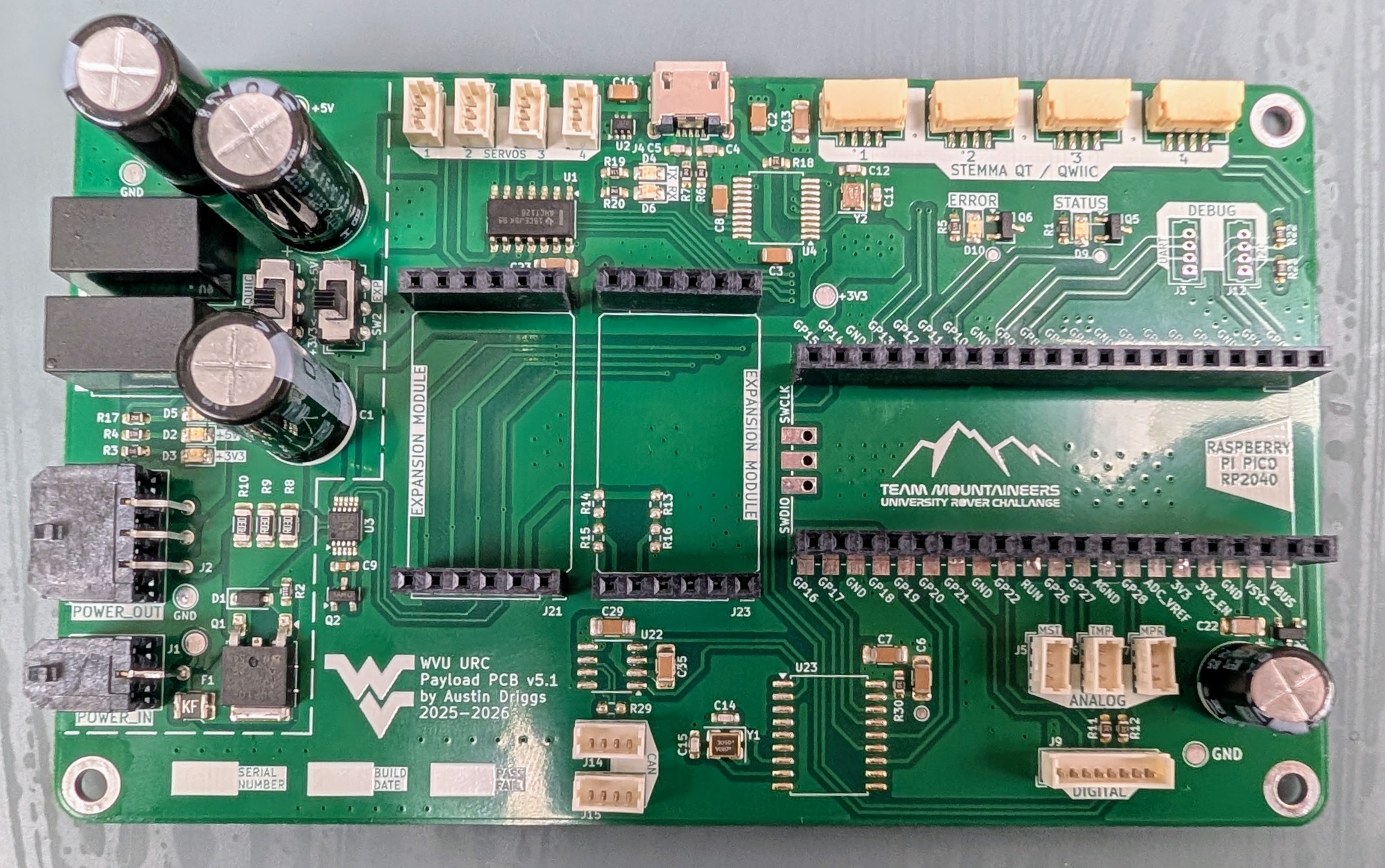
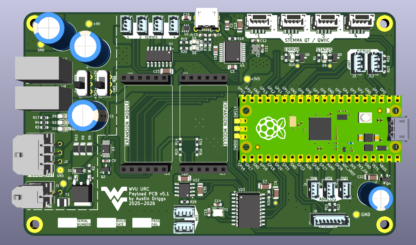
The Payload PCB serves as an all-purpose control and interface board that contains the Raspberry Pi Pico (RP2040) designed to manage mission-critical sensors and electronics and communicate that information through its Micro USB connector to the LattePanda Sigma SBC.
Learn how to contribute (with pictures) to this project.
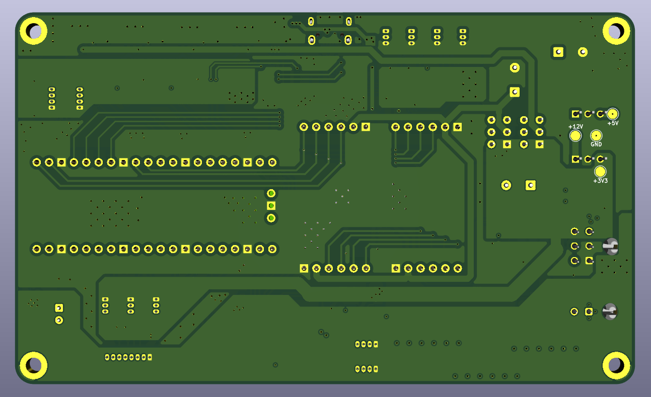
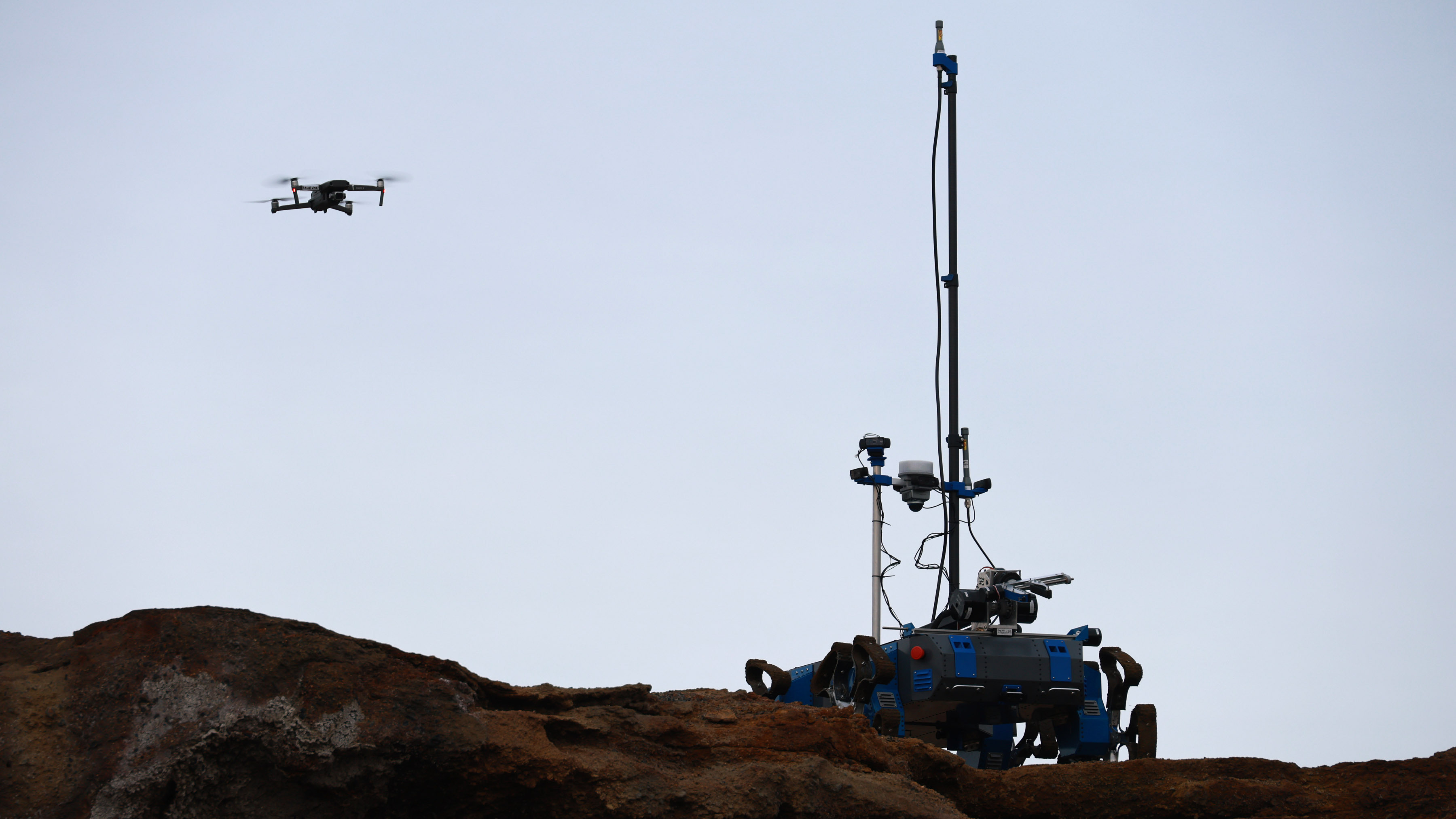
Click the image below to watch the System Acceptance Review (SAR) on YouTube:
This project is published under the MIT license.
| Qty | Value | Footprint | References |
|---|---|---|---|
| 8 | 10k | Resistor_SMD:R_0603_1608Metric_Pad0.98x0.95mm_HandSolder | R11, R12, R13, R14, R15, R16, R18, R30 |
| 7 | 0.1uF | Capacitor_SMD:C_1206_3216Metric_Pad1.33x1.80mm_HandSolder | C6, C7, C13, C22, C23, C29, C35 |
| 5 | 22 | Resistor_SMD:R_0603_1608Metric_Pad0.98x0.95mm_HandSolder | R1, R3, R6, R7, R20 |
| 4 | 0.1uF | Capacitor_SMD:C_0805_2012Metric_Pad1.18x1.45mm_HandSolder | C2, C3, C8, C16 |
| 4 | 12pF | Capacitor_SMD:C_0603_1608Metric_Pad1.08x0.95mm_HandSolder | C11, C12, C14, C15 |
| 4 | GND | TestPoint:TestPoint_Pad_D2.0mm | TP2, TP9, TP10, TP11 |
| 4 | MountingHole | MountingHole:MountingHole_3.2mm_M3_DIN965_Pad | H1, H2, H3, H4 |
| 3 | 1000uF | Capacitor_THT:CP_Radial_D10.0mm_P5.00mm | C1, C10, C25 |
| 3 | 30m | Resistor_SMD:R_1206_3216Metric_Pad1.30x1.75mm_HandSolder | R8, R9, R10 |
| 3 | 330 | Resistor_SMD:R_0603_1608Metric_Pad0.98x0.95mm_HandSolder | R4, R5, R19 |
| 2 | +3V3 | TestPoint:TestPoint_Pad_D2.0mm | TP6, TP8 |
| 2 | +5V | TestPoint:TestPoint_Pad_D2.0mm | TP4, TP7 |
| 2 | 2N7002 | Package_TO_SOT_SMD:TSOT-23 | Q5, Q6 |
| 2 | 3k3 | Resistor_SMD:R_0603_1608Metric_Pad0.98x0.95mm_HandSolder | R22, R23 |
| 2 | 47p | Capacitor_SMD:C_0603_1608Metric_Pad1.08x0.95mm_HandSolder | C4, C5 |
| 2 | CAN | Connector_Molex:Molex_PicoBlade_53047-0410_1x04_P1.25mm_Vertical | J14, J15 |
| 1 | +12V | LED_SMD:LED_0805_2012Metric_Pad1.15x1.40mm_HandSolder | D5 |
| 1 | +12V | TestPoint:TestPoint_Pad_D2.0mm | TP5 |
| 1 | +12V_IN | TestPoint:TestPoint_Pad_D2.0mm | TP1 |
| 1 | +3V3 | LED_SMD:LED_0805_2012Metric_Pad1.15x1.40mm_HandSolder | D3 |
| 1 | +3V3@2A | footprints:TSR_2-24xx | U12 |
| 1 | +5V | LED_SMD:LED_0805_2012Metric_Pad1.15x1.40mm_HandSolder | D2 |
| 1 | +5V@2A | footprints:TSR_2-24xx | U9 |
| 1 | 100k | Resistor_SMD:R_0603_1608Metric_Pad0.98x0.95mm_HandSolder | R2 |
| 1 | 10uF | Capacitor_THT:CP_Radial_D8.0mm_P2.50mm | C20 |
| 1 | 120 | Resistor_SMD:R_0603_1608Metric_Pad0.98x0.95mm_HandSolder | R29 |
| 1 | 12MHz | Crystal:Crystal_SMD_2520-4Pin_2.5x2.0mm | Y2 |
| 1 | 1k78 | Resistor_SMD:R_0603_1608Metric_Pad0.98x0.95mm_HandSolder | R17 |
| 1 | 470pF | Capacitor_SMD:C_0603_1608Metric_Pad1.08x0.95mm_HandSolder | C9 |
| 1 | 8MHz | Crystal:Crystal_SMD_3225-4Pin_3.2x2.5mm | Y1 |
| 1 | BZT52C10-TP | Diode_SMD:D_SOD-123 | D1 |
| 1 | DIGITAL | Connector_Molex:Molex_PicoBlade_53047-0810_1x08_P1.25mm_Vertical | J9 |
| 1 | DMG2305UX | Package_TO_SOT_SMD:SOT-23 | Q4 |
| 1 | ERROR | LED_SMD:LED_0805_2012Metric_Pad1.15x1.40mm_HandSolder | D10 |
| 1 | EXP | Button_Switch_THT:SW_E-Switch_EG1271_SPDT | SW2 |
| 1 | EXP1 | Connector_PinSocket_2.54mm:PinSocket_1x06_P2.54mm_Vertical | J20 |
| 1 | EXP2 | Connector_PinSocket_2.54mm:PinSocket_1x06_P2.54mm_Vertical | J21 |
| 1 | EXP3 | Connector_PinSocket_2.54mm:PinSocket_1x06_P2.54mm_Vertical | J22 |
| 1 | EXP4 | Connector_PinSocket_2.54mm:PinSocket_1x06_P2.54mm_Vertical | J23 |
| 1 | I2C | Connector_Molex:Molex_PicoBlade_53047-0410_1x04_P1.25mm_Vertical | J12 |
| 1 | LED1 | TestPoint:TestPoint_Pad_D1.0mm | TP12 |
| 1 | LED2 | TestPoint:TestPoint_Pad_D1.0mm | TP13 |
| 1 | LTC2990 | Package_SO:MSOP-10_3x3mm_P0.5mm | U3 |
| 1 | MANIPULATOR | Connector_Molex:Molex_PicoBlade_53047-0310_1x03_P1.25mm_Vertical | J18 |
| 1 | MCP2200 | Package_SO:SSOP-20_5.3x7.2mm_P0.65mm | U4 |
| 1 | MCP2515 | Package_SO:SOIC-18W_7.5x11.6mm_P1.27mm | U23 |
| 1 | MCP2562 | Package_SO:SOIC-8_3.9x4.9mm_P1.27mm | U22 |
| 1 | MIC94093YC6 | Package_TO_SOT_SMD:SOT-363_SC-70-6 | U2 |
| 1 | MMBT3904 | Package_TO_SOT_SMD:SOT-23 | Q2 |
| 1 | MPR | Connector_Molex:Molex_PicoBlade_53047-0310_1x03_P1.25mm_Vertical | J7 |
| 1 | MST | Connector_Molex:Molex_PicoBlade_53047-0310_1x03_P1.25mm_Vertical | J5 |
| 1 | PI_PICO | footprints:RPi_Pico_SMD_TH | U14 |
| 1 | POWER_IN | Connector_Molex:Molex_Micro-Fit_3.0_43045-0200_2x01_P3.00mm_Horizontal | J1 |
| 1 | POWER_OUT | Connector_Molex:Molex_Micro-Fit_3.0_43045-0600_2x03_P3.00mm_Horizontal | J2 |
| 1 | PTC | Fuse:Fuse_1210_3225Metric | F1 |
| 1 | QUIIC | Button_Switch_THT:SW_E-Switch_EG1271_SPDT | SW1 |
| 1 | QWIIC1 | Connector_JST:JST_GH_BM04B-GHS-TBT_1x04-1MP_P1.25mm_Vertical | J13 |
| 1 | QWIIC2 | Connector_JST:JST_GH_BM04B-GHS-TBT_1x04-1MP_P1.25mm_Vertical | J11 |
| 1 | QWIIC3 | Connector_JST:JST_GH_BM04B-GHS-TBT_1x04-1MP_P1.25mm_Vertical | J10 |
| 1 | QWIIC4 | Connector_JST:JST_GH_BM04B-GHS-TBT_1x04-1MP_P1.25mm_Vertical | J8 |
| 1 | RX | LED_SMD:LED_0805_2012Metric_Pad1.15x1.40mm_HandSolder | D6 |
| 1 | SCOOP | Connector_Molex:Molex_PicoBlade_53047-0310_1x03_P1.25mm_Vertical | J19 |
| 1 | SERVO3 | Connector_Molex:Molex_PicoBlade_53047-0310_1x03_P1.25mm_Vertical | J17 |
| 1 | SERVO4 | Connector_Molex:Molex_PicoBlade_53047-0310_1x03_P1.25mm_Vertical | J16 |
| 1 | SN74AHCT126DR | Package_SO:SOIC-14_3.9x8.7mm_P1.27mm | U1 |
| 1 | STATUS | LED_SMD:LED_0805_2012Metric_Pad1.15x1.40mm_HandSolder | D9 |
| 1 | SUD50P10-43L-GE3 | Package_TO_SOT_SMD:TO-252-2 | Q1 |
| 1 | TMP | Connector_Molex:Molex_PicoBlade_53047-0310_1x03_P1.25mm_Vertical | J6 |
| 1 | TX | LED_SMD:LED_0805_2012Metric_Pad1.15x1.40mm_HandSolder | D4 |
| 1 | UART | Connector_Molex:Molex_PicoBlade_53047-0410_1x04_P1.25mm_Vertical | J3 |
| 1 | USB | Connector_USB:USB_Micro-B_Wuerth_629105150521 | J4 |
| 1 | ~{RST} | TestPoint:TestPoint_Pad_D1.0mm | TP15 |
The 113 most common of 114 parts.
It measures 127 × 76.2 mm and has 4 copper layers, 1.59 mm thick.
114 parts, built around the MCP2562-H/P, SC0915, LTC2990IMS#TRPBF and MCP2200-I/SS. The full list of its parts is on this page, with links to each part's symbol and footprint where PCBKit's library has them.
From the austindriggs/urc-payload-pcb repository on GitHub, at the commit this page was made from: the board is payload-pcb.kicad_pcb and its schematic can.kicad_sch. PCBKit opens the board in the browser, with nothing to install.
Its repository publishes it under the MIT licence: you may reuse it on that licence's terms (keep the author's notice, and for a copyleft licence share your changes alike).
team-mountaineers-urc-2023/electronics
Block diagrams, schematics, and PCB files related to the electronics subteam


drewsipher/sharkcnc
Open CNC control stack for a Sherline 2000: FluidNC ESP32-S3 breakout hardware + host software plan

agausmann/riemann-kb-pre1
Riemann: A 60% pseudo-split ortholinear keyboard.

austindriggs/spacex-sbc
Complete PCB architecture and design process for a custom SBC prepared for a technical interview presentation for a PCB Design Engineer at SpaceX before I graduated from WVU.

bjthemost-hub/l103-drv8313-as5600
Joint motor driver: CH32L103 + DRV8313 + AS5600. KiCad hardware, FOC firmware, PC tools, 2-stage planetary gearbox (J, 25:1). MIT.