2 layers120 × 100 mm
Onstep
andshn/OnStep_STM32_PCB
This is a PCB for OnStep, designed for 1455N1201 case. In the board use XLR connectors for steper drivers. The DB9 connector use for the hand controller.
137 parts3CC-BY-SA-4.0

 arkorobotics/robocar-pinky12
DIY Robocar Project - Codename Pinky
Glue Board is an open-source printed circuit board by arkorobotics, from the arkorobotics/robocar-pinky repository on GitHub. It is a 4-layer board of 81.3 × 52.8 mm with 87 parts on 83 nets, routed with 823 tracks and 133 vias.
It is built around the R-745.0D, ADS1115IDGS and AMC1301DWVR, with the DRV8871DDA, PCA9685PW and VNH5019ATR-E among its other parts. Its parts include 35 resistors, 23 capacitors, 9 ICs, 8 connectors and 4 diodes.


Pinky is a 1/16 scale DIY autonomous car designed to compete in the DIY Robocar race. Pinky also has a counterpart testbed named Brain.
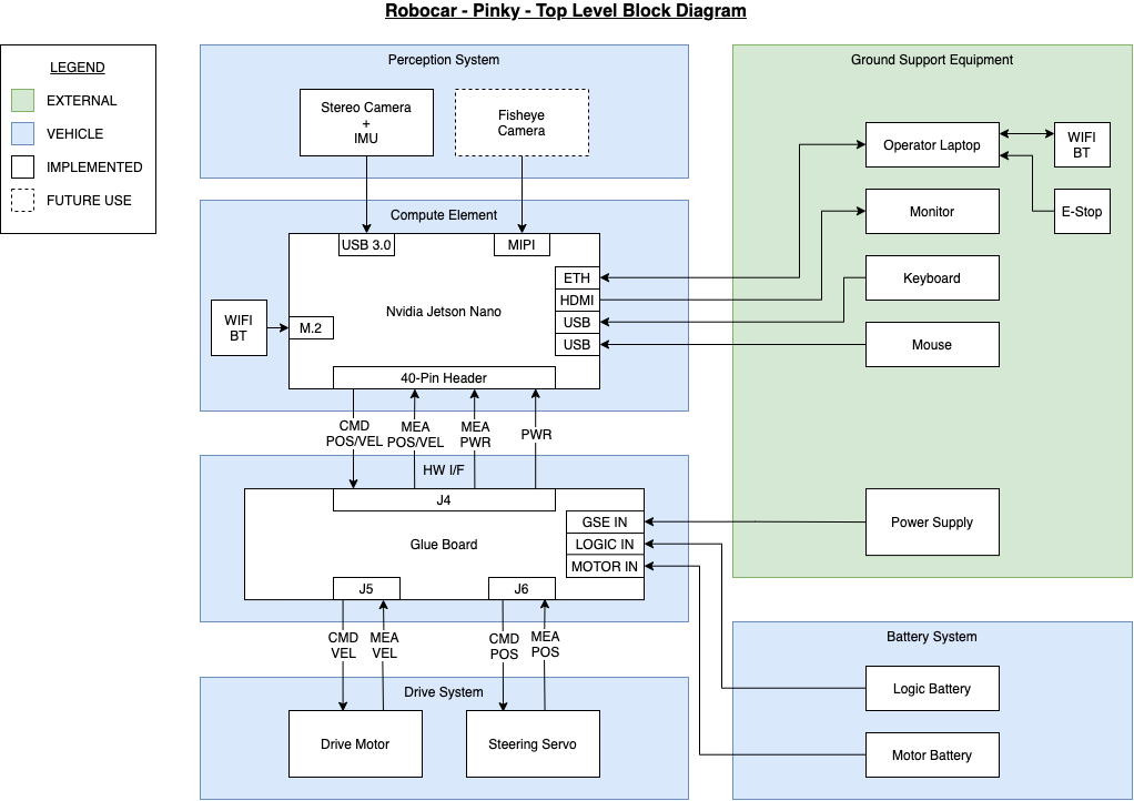
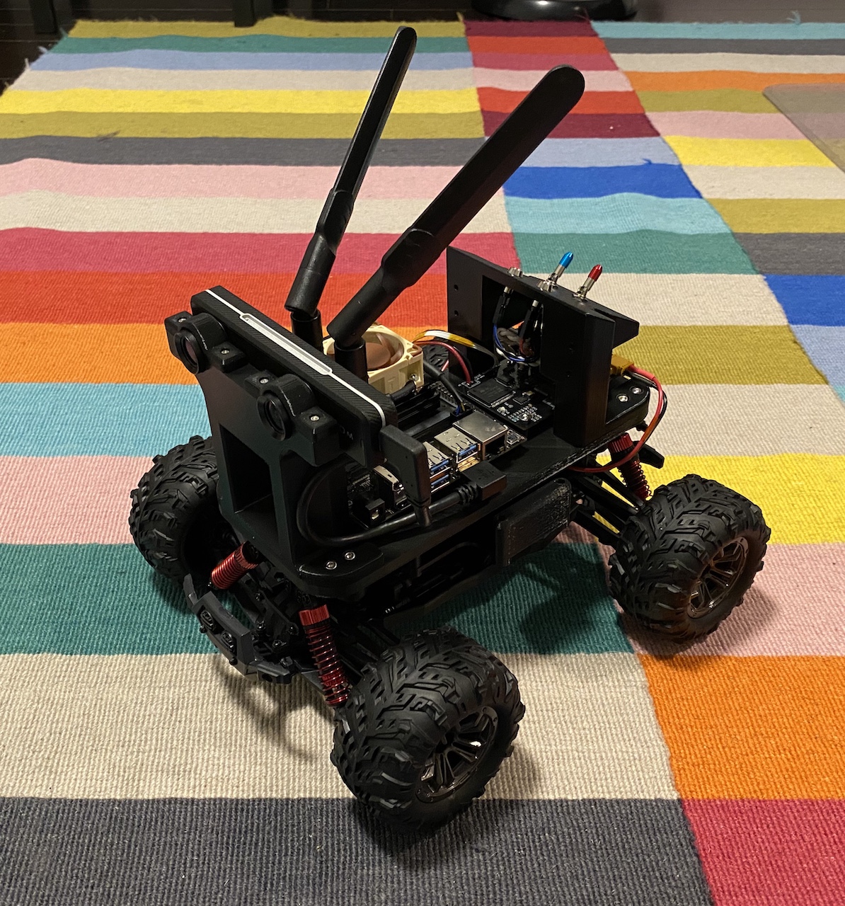
See the Software subfolder.
| Part | Cost | Link |
|---|---|---|
| ZED Mini | $399.00 | Stereo Labs Store |
| IMX219 Camera Module (Fisheye) | $29.99 | Amazon |
| Part | Cost | Link |
|---|---|---|
| NVIDIA Jetson Nano Developer Kit | $98.98 | Amazon |
| Intel Dual Band Wireless-Ac 8265 w/ BT Module | $21.55 | Amazon |
| Noctua Fan | $14.95 | Amazon |
| Part | Cost | Link |
|---|---|---|
| Glue Board (Fab/Assembly Required) | ~$300.00 | GitHub |
| Part | Cost | Link |
|---|---|---|
| VATOS RC Car 9137R | $54.99 | Amazon |
| Part | Cost | Link |
|---|---|---|
| Screw Set | $20.98 | Amazon |
| Threaded Heat Insert | $19.99 | Amazon |
| 3D Printable Models (Fab/Assembly Required) | ~$20.00 | GitHub |
| Part | Cost | Link |
|---|---|---|
| ENGPOW 7.4V 3000mah 30C Lipo Battery | $22.99 | Amazon |
| Samsung SD Car 128GB | $16.99 | Amazon |
| 1.5 ft/50cm Micro USB 3.0 Cable | $8.79 | Amazon |
| 5V/4A 20W Switching Power | $8.99 | Amazon |
| WiFi/BT Antennas | $13.99 | Amazon |
| USB 3.1 Right Angle A to Right Angle C | $19.25 | UsbFirewire |

For 3D printed models, use the Autodesk Fusion 360 Pinky CAD model for assembly.
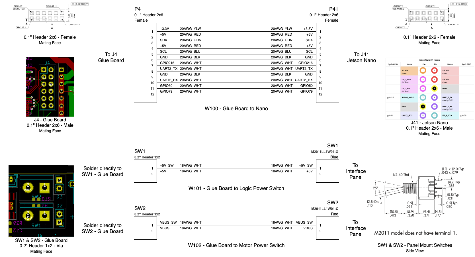
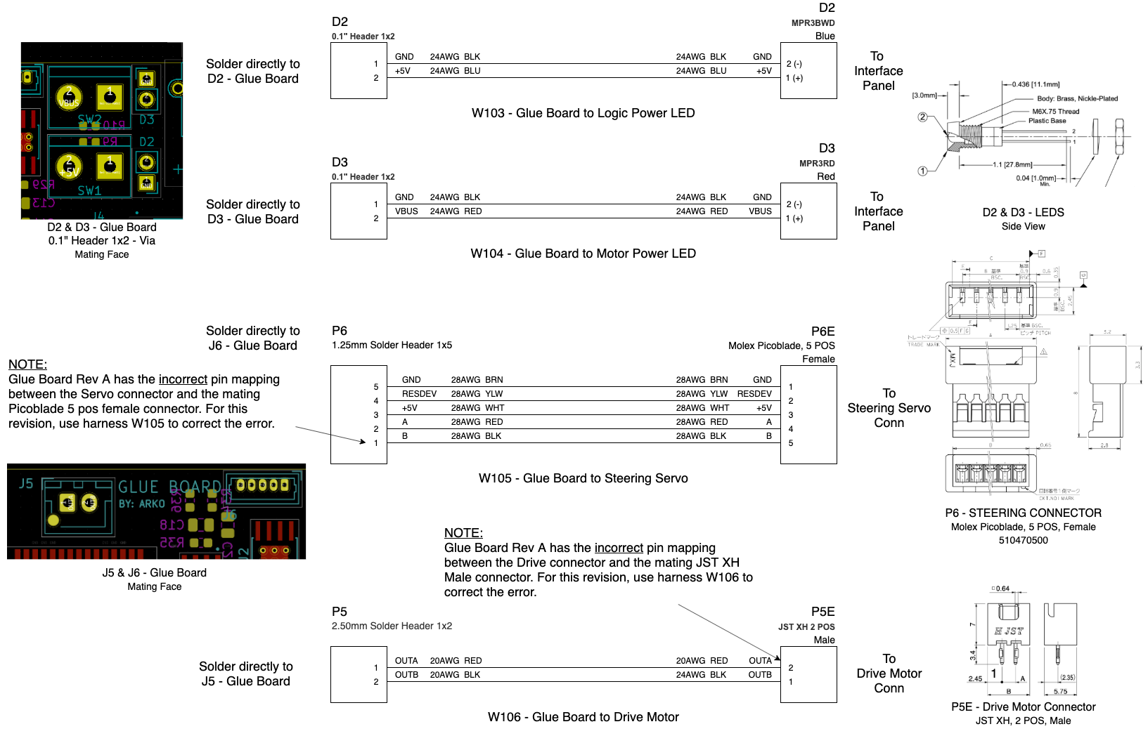
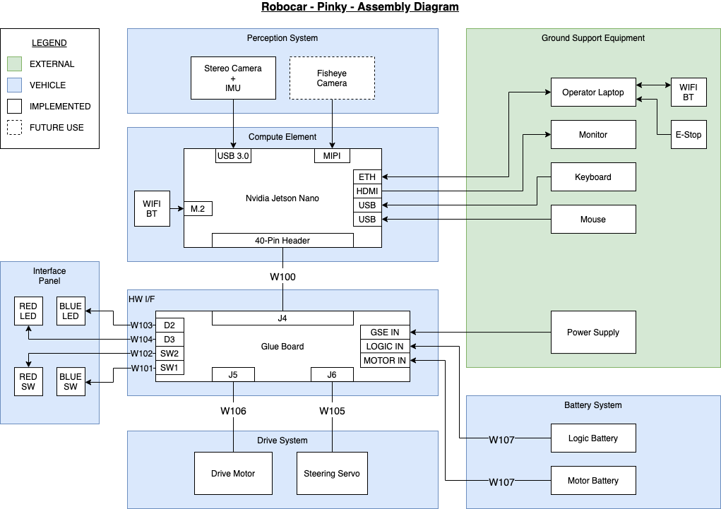
For electrical assembly, see diagram below:
| Qty | Value | Footprint | References |
|---|---|---|---|
| 14 | 10k | Resistor_SMD:R_0603_1608Metric | R11, R12, R13, R19, R26, R31, R32, R33, R34, R36, R37, R38, R39, R40 |
| 8 | 1uF | Capacitor_SMD:C_0805_2012Metric | C1, C2, C4, C6, C7, C17, C22, C23 |
| 6 | 1k | Resistor_SMD:R_0603_1608Metric | R20, R21, R22, R23, R24, R28 |
| 4 | 0.1uF | Capacitor_SMD:C_0805_2012Metric | C10, C12, C14, C16 |
| 3 | 100uF | Capacitor_SMD:C_1210_3225Metric | C3, C5, C9 |
| 3 | 10uF | Capacitor_SMD:C_0805_2012Metric | C8, C19, C20 |
| 3 | 33nF | Capacitor_SMD:C_0805_2012Metric | C11, C18, C21 |
| 3 | 4.7k | Resistor_SMD:R_0603_1608Metric | R25, R27, R30 |
| 3 | 5k | Resistor_SMD:R_0603_1608Metric | R2, R5, R7 |
| 3 | TestPoint | TestPoint:TestPoint_Pad_D4.0mm | JLBAT1, JMBAT1, JVBUS1 |
| 2 | 23.7k | Resistor_SMD:R_0603_1608Metric | R1, R6 |
| 2 | Conn_01x02_Male | Connector_AMASS:AMASS_XT30PW-M_1x02_P2.50mm_Horizontal | J1, J3 |
| 2 | INA260 | Package_SO:TSSOP-16_4.4x5mm_P0.65mm | U8, U9 |
| 2 | LED | Connector_PinHeader_2.54mm:PinHeader_1x02_P2.54mm_Vertical | D2, D3 |
| 2 | SW_SPST | TerminalBlock:TerminalBlock_bornier-2_P5.08mm | SW1, SW2 |
| 1 | 10.2k | Resistor_SMD:R_0603_1608Metric | R4 |
| 1 | 18.7k | Resistor_SMD:R_0603_1608Metric | R8 |
| 1 | 2.6k | Resistor_SMD:R_0603_1608Metric | R3 |
| 1 | 22uF | Capacitor_SMD:C_0805_2012Metric | C13 |
| 1 | 30K | Resistor_SMD:R_0603_1608Metric | R29 |
| 1 | 470 | Resistor_SMD:R_0603_1608Metric | R10 |
| 1 | 470R | Resistor_SMD:R_0603_1608Metric | R35 |
| 1 | 47R | Resistor_SMD:R_0603_1608Metric | R9 |
| 1 | 47uF | Capacitor_SMD:C_0805_2012Metric | C15 |
| 1 | ADS1115IDGS | Package_SO:TSSOP-10_3x3mm_P0.5mm | U4 |
| 1 | AMC1301DWVR | libs:SOIC127P1150X280-8N | U7 |
| 1 | Barrel_Jack | Connector_BarrelJack:BarrelJack_Horizontal | J2 |
| 1 | CSD17501Q5A | Package_TO_SOT_SMD:TDSON-8-1 | Q1 |
| 1 | Conn_01x02_Male | Connector_JST:JST_XH_B2B-XH-AM_1x02_P2.50mm_Vertical | J5 |
| 1 | Conn_01x04_Male | Connector_PinHeader_2.54mm:PinHeader_1x04_P2.54mm_Vertical | J7 |
| 1 | Conn_01x05_Female | Connector_Molex:Molex_PicoBlade_53047-0510_1x05_P1.25mm_Vertical | J6 |
| 1 | Conn_02x03_Odd_Even | Connector_IDC:IDC-Header_2x03_P2.54mm_Vertical | J8 |
| 1 | Conn_02x06_Odd_Even | Connector_PinHeader_2.54mm:PinHeader_2x06_P2.54mm_Vertical | J4 |
| 1 | DRV8871DDA | Package_SO:Texas_HTSOP-8-1EP_3.9x4.9mm_P1.27mm_EP2.95x4.9mm_Mask2.4x3.1mm_ThermalVias | U2 |
| 1 | LED_Dual_2pin | LED_SMD:LED_1206_3216Metric | D4 |
| 1 | NCP1117-5.0_SOT223 | Package_TO_SOT_SMD:SOT-223-3_TabPin2 | U5 |
| 1 | PCA9685PW | Package_SO:TSSOP-28_4.4x9.7mm_P0.65mm | U1 |
| 1 | R-745.0D | libs:CONV_R-745.0D | PS1 |
| 1 | STPS5L60S | agg:DO-214AB-SMC | D1 |
| 1 | TPS2121RUXR | libs:IC_TPS2121RUXR | U6 |
| 1 | TestPoint | TestPoint:TestPoint_Pad_D2.0mm | TP1 |
| 1 | VNH5019ATR-E | Package_SO:ST_MultiPowerSO-30 | U3 |
andshn/OnStep_STM32_PCB
This is a PCB for OnStep, designed for 1455N1201 case. In the board use XLR connectors for steper drivers. The DB9 connector use for the hand controller.


saikhamhein/benchswitch-usb-dut-hub
BenchSwitch USB DUT Hub: a four-port USB 2.0 hardware development prototype with KiCad design sources, BOM, manufacturing files, and bring-up documentation.

UChicago-Space-Program/pulse-hardware
This is the central repository for documents related to PULSE-A hardware development.

Boardoza/Boardoza_VNH5019ATR_w-Enc_Elite_Breakout_Board
High-power H-bridge motor driver breakout board based on STMicroelectronics VNH5019A-E with integrated encoder interface and thermal heatsink design.

Accessibilita/recline-controls
Hardware project for open source wheel chair recline control electronics

Boardoza/Boardoza_VNH5019_H_Bridge_Motor_Driver_Module
B-VNH5019-BRK is a high-current full H-bridge motor driver module based on the VNH5019A-E for 5.5V–24V DC motor control.

It measures 81.3 × 52.8 mm and has 4 copper layers, 1.6 mm thick.
87 parts, built around the R-745.0D, ADS1115IDGS, AMC1301DWVR and DRV8871DDA. The full list of its parts is on this page, with links to each part's symbol and footprint where PCBKit's library has them.
From the arkorobotics/robocar-pinky repository on GitHub, at the commit this page was made from: the board is Electronics/Glue Board/Glue Board.kicad_pcb. PCBKit opens the board in the browser, with nothing to install.
Its repository states no licence, so its author keeps all rights: ask arkorobotics before reusing the design.