
2 layers100 × 80 mm
Dlr sensor hat
arcnode-io/dlr-rtu-pcb
Solar-powered RTU sensor HAT for transmission tower DLR deployment
24 parts
 arcnode-io/dlr-rtu-pcb
Solar-powered RTU sensor HAT for transmission tower DLR deployment
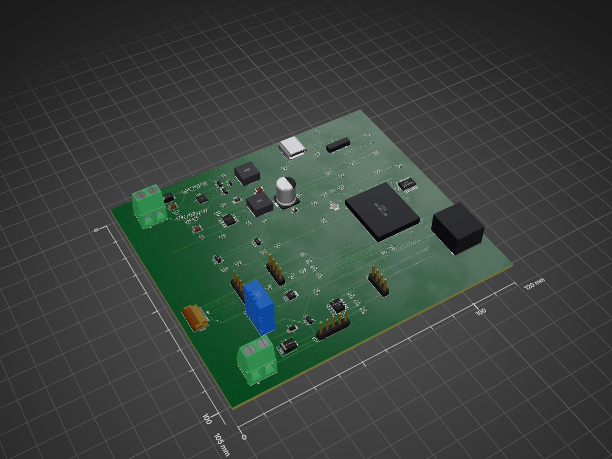
Dlr carrier is an open-source printed circuit board by arcnode-io, from the arcnode-io/dlr-rtu-pcb repository on GitHub. It is a 4-layer board of 120 × 105 mm with 89 parts on 90 nets, routed with 1,363 tracks and 193 vias.
It is built around the DHT22, LMR33630ADDA and ADS1115, with the AP2112K-3.3, BQ24650RVAR and SP3485EN-Y among its other parts. Its parts include 36 capacitors, 24 resistors, 11 connectors, 9 ICs and 4 diodes. It belongs with the power and sensors and measurement boards of this library.





Single-PCB CM4 carrier for a solar-powered, cellular-connected RTU — mounts to a transmission tower cross-arm, integrates SoM + cellular modem + IEEE 738 sensor suite + solar/LiFePO4 power management. Feeds
dlr-rtu-firmware.
Solar-powered remote terminal unit (RTU) deployed unattended on transmission tower cross-arms. A ~20W solar panel and ~50Wh LiFePO4 battery keep the CM4 running indefinitely with cellular PSM idle. A soldered Quectel BG770A (LTE Cat-M1) publishes sensor data and dynamic ratings to the MQTT broker — no site WiFi or wired backhaul required. The unit is designed for 30-year conductor-adjacent deployment with no scheduled maintenance.
~100x80mm 4-layer industrial carrier. Raspberry Pi CM4 (DF40 dual-connector) + Quectel BG770A LCC + FLIR Lepton 3.5 (SPI) + DHT22 (GPIO) + SI1145 (I2C) + YL-83 (analog via ADS1115). MPPT charger from PV input, LiFePO4 BMS, buck for 5V SoM rail, AP2112K LDO for 3.3V analog front-end. Conformal coated, IP55 when potted in field enclosure.
rectangle transmission_tower {
  rectangle field_enclosure {
    rectangle dlr_carrier {
      rectangle cm4_som
      rectangle cellular_module
      rectangle sensors
      rectangle power_mgmt
    }
  }
  rectangle solar_panel
  rectangle lifepo4_battery
  rectangle conductor
}

queue mqtt_broker
rectangle dispatch_api

solar_panel -d- power_mgmt: PV input
power_mgmt -l- lifepo4_battery: charge / discharge
power_mgmt -d- cm4_som: 5V / 3V3
conductor -u- sensors: thermal view\n(FLIR Lepton)
sensors -r- cm4_som: SPI / I2C / GPIO
cm4_som -r- cellular_module: UART + USB2
cellular_module -r- mqtt_broker: LTE Cat-M1
mqtt_broker -r- dispatch_api: dynamic line rating\n(utility/dlr/...)
The carrier is the physical sensing + edge-compute layer of the DLR feedback loop. Every measurement flows through the IEEE 738 calculation in dlr-rtu-firmware, which publishes the resulting dynamic line rating for mock-derms-dispatch-api's DER curtailment trigger.
graph LR
    SOLAR["Solar Panel<br/>~20W 12V"] --> MPPT["BQ24650 MPPT<br/>+ 2x DMN4035L"]
    MPPT --> BAT["LiFePO4 4S<br/>~50Wh + BMS"]
    BAT --> BUCK["Buck<br/>5V 3A"]
    BUCK --> CM4["CM4 SoM<br/>DF40 x2"]
    BUCK --> BG["Quectel BG770A<br/>Cat-M1 LCC"]
    BUCK --> LDO["AP2112K<br/>3.3V LDO"]
    LDO --> ADC["ADS1115<br/>I2C 0x48"]
    LDO --> UV["SI1145<br/>I2C 0x60"]
    CM4 --> FLIR["FLIR Lepton 3.5<br/>SPI0 + GPIO25"]
    CM4 --> DHT["DHT22<br/>GPIO4"]
    CM4 --> ADC
    CM4 --> UV
    ADC --> RAIN["YL-83<br/>Analog 0-3.3V"]

    style SOLAR fill:#dc4,stroke:#333
    style MPPT fill:#a94,stroke:#333
    style BAT fill:#a94,stroke:#333
    style BUCK fill:#a94,stroke:#333
    style LDO fill:#a94,stroke:#333
    style CM4 fill:#4a9,stroke:#333,color:#fff
    style BG fill:#49a,stroke:#333,color:#fff
    style FLIR fill:#49a,stroke:#333,color:#fff
style DHT fill:#94a,stroke:#333,color:#fffflowchart LR
classDef default fill:transparent,stroke:#333
classDef pwr fill:#4a9,stroke:#333,color:#fff
classDef spi fill:#49a,stroke:#333,color:#fff
classDef i2c fill:#94a,stroke:#333,color:#fff
classDef gpio fill:#a94,stroke:#333,color:#fff
classDef uart fill:#a49,stroke:#333,color:#fff
classDef usb fill:#669,stroke:#333,color:#fff
subgraph cm4 ["CM4 (DF40-100)"]
p_5v["5V_IN"]
p_sda["GPIO2 SDA1"]
p_scl["GPIO3 SCL1"]
p_g4["GPIO4"]
p_g25["GPIO25"]
p_mosi["GPIO10 MOSI"]
p_miso["GPIO9 MISO"]
p_sck["GPIO11 SCLK"]
p_ce0["GPIO8 CE0"]
p_txd["GPIO14 TXD"]
p_rxd["GPIO15 RXD"]
p_usb["USB2 D+/D-"]
end
| Sensor | Interface | CM4 Pins | Sample Rate | Measurement | Feeds IEEE 738 Variable |
|---|---|---|---|---|---|
| FLIR Lepton 3.5 | SPI0 + VSYNC | GPIO 8, 9, 10, 11, 25 | 8.6 Hz (frame) | Conductor surface temp | $R_{thermal}$ |
| DHT22 | GPIO4 (1-Wire) | GPIO 4 | 0.5 Hz | Ambient temp + humidity | $T_{amb}$ |
| SI1145 | I2C (0x60) | GPIO 2, 3 | 10 Hz | UV / Visible / IR irradiance | $\Delta T_{solar}$ |
| YL-83 → ADS1115 | I2C (0x48) ch0 | GPIO 2, 3 | 860 SPS | Rain intensity (0–3.3V analog) | $\Delta T_{rain}$ |
Every sensor reading on this board maps to exactly one term in the IEEE 738 dynamic rating equation:
$$ I_{max} = \sqrt{\frac{q_c + q_r - q_s}{R_{ac}}} $$
Single PCB + single firmware binary. Variant lives in the kit BOM — sensor,
cable harness, PV panel, and battery differ per SKU. Both sensors speak
NMEA 0183 ($..MWV) over RS-485, so the firmware driver is talker-agnostic.
| Component | High-wind kit (DLR-CRN-HW) | Low-wind kit (DLR-CRN-LW) |
|---|---|---|
| PCB | dlr-rtu-pcb-v1 (same) | dlr-rtu-pcb-v1 (same) |
| Firmware | dlr-rtu-firmware (same binary) | dlr-rtu-firmware (same binary) |
| Sensor | Calypso ULP STD | Vaisala WMT702 |
| Sensor wire protocol | NMEA $IIMWV over RS-485 | NMEA $WIMWV over RS-485 |
| Sensor accuracy (V<2 m/s) | ±5 % + 0.2 m/s offset (1 m/s threshold) | ±0.1 m/s (0.01 m/s threshold) |
| Sensor op temp | unspecified (consumer-grade) | -10 to +60 °C |
| Cable harness | 5 m bare-wire to M12-5P | 5 m Cannon Trident 19-way to M12-5P |
| PV panel | 20 W | 30 W |
| Battery | 50 Wh LiFePO4 | 100 Wh LiFePO4 |
| Sticker | HW-1.0 | LW-1.0 |
| Kit cost (approx) | ~$650 | ~$2350 |
Per-site SKU pick uses NREL WIND Toolkit climatology (or customer SCADA wx history when available). Threshold: fraction-of-year with V_w < 1 m/s perpendicular to conductor.
| Climatology | Variant | Why |
|---|---|---|
| ≤ 15 % yr V_w < 1 m/s (ridge / coastal / open plain w/ mean ≥ 6 m/s) | high-wind | uplift slice below 1 m/s is marginal; static fallback below threshold is fine |
| > 15 % yr V_w < 1 m/s (valley / sheltered / open plain w/ mean ≤ 5 m/s) | low-wind | uplift slice is material; pay $1.7 k premium to capture it |
When the sensor reports void status, times out, or has a checksum/parse
error, the driver returns None. The IEEE 738 layer collapses None →
V_w = 0.0 → natural-convection-only ampacity = the conductor's static
rating. Same conservative fallback used for the icing-fallback policy.
| High-wind | Low-wind | |
|---|---|---|
| Sensor continuous draw | 1 mW | 480 mW |
| System daily energy | 29.1 Wh | 40.6 Wh |
| Winter PV harvest (worst) | 45 Wh | 67.5 Wh |
| Winter margin | 1.55× | 1.66× |
| Battery autonomy at 0 PV | 1.58 d | 2.22 d |
Low-wind variant's 30 W / 100 Wh upgrade absorbs the WMT702's higher draw and restores both winter margin and 2-day autonomy.
| Rail | Source | Consumer | Idle (PSM) | Typical | Peak |
|---|---|---|---|---|---|
| 5V | Buck | CM4 | 80 mA | 1400 mA | 3000 mA (boot) |
| 5V | Buck | Quectel BG770A | <1 mA | 100 mA | 250 mA (TX) |
| 5V | Buck | FLIR Lepton 3.5 | 150 mA | 150 mA | 650 mA (shutter) |
| 5V | Buck | DHT22 | 1.5 mA | 1.5 mA | 2.5 mA |
| 3.3V | AP2112K LDO | ADS1115 + SI1145 + YL-83 | 9 mA | 9 mA | 14 mA |
| Total @ 5V equiv | 240 mA | 1660 mA | 3920 mA |
The 3920 mA peak is a worst-case sum, not a supported operating point. The LMR33630 delivers 3.375 A with worst-case silicon, so a coincident CM4-boot + Lepton-shutter + modem-TX peak browns the rail out below the CM4's 4.75 V floor — firmware sequences those loads apart (ADR-017, derived in theory.ipynb §7 and asserted in sim/test_spice.py). The CM4 boot peak on its own holds the rail at ~4.95 V.
Daily energy with CM4-always-on idle + 1/min sensor wake + 1/15 min cellular TX: ~29 Wh/day (derived in theory.ipynb). A 50 Wh battery (90% DoD) gives ~1.6 days autonomy with no PV. A 20W panel at 2.5 sun-hours/day (winter Northeast US worst case) delivers ~45 Wh/day after MPPT η — 1.55x winter margin, 2.5x annual avg.
That margin assumes a 120 mA CM4 idle (tuned Pi OS Lite, headless). The CM4 datasheet §5.3 quotes ~400 mA typical idle; at that figure the budget is 62.6 Wh/day and the 20 W panel does not carry winter (0.72x). Idle current is the single measurement that most needs a bench check before committing to the panel size.
| Parameter | Spec | Notes |
|---|---|---|
| Operating temp | -20°C to +85°C | CM4 commercial spec; cold-start heater required below -20°C |
| Conformal coat | Dow Corning 1-2577 | Applied post-assembly, mask connectors |
| Enclosure rating | IP55 (with field enclosure) | Board alone is not rated |
| Vibration | IEC 60068-2-6 (5–500 Hz, 2g) | Transmission tower wind loading |
| Expected service life | 30 years | Matches conductor replacement cycle |
| MTBF | >200,000 hours | Derated per MIL-HDBK-217F |
| Mounting | M3 standoffs, 4-corner | Single rigid PCB — no stack |
Fully scripted — no GUI step. KiCad's "Update PCB from Schematic" is GUI-only, so cad/drawing/sync_pcb.py does the same job from the SKiDL netlist: it rebuilds every footprint from the library and reassigns every pad net, which is what keeps the board honest about what the schematic says.
 1. uv run poe notebook         → theory.ipynb: power, signal integrity, 5V transients
 2. uv run poe build            → SKiDL netlist
 3. uv run poe schematic        → hierarchical .kicad_sch (one sheet per block)
 4. uv run poe validate-model   → ERC, 0 violations (exits non-zero otherwise)
 5. uv run poe sim / cover      → pytest: hand calcs + ngspice transients

 6. uv run poe layout-asm       → the whole board flow, in order:
      build       netlist from SKiDL
      sync-asm    footprints + pad nets  <- replaces the GUI "Update PCB from Schematic"
      place-asm   positions from cad/pcb_placement.yaml
      setup-asm   4-layer stack, design rules, net classes, GND + 5V planes
      fanout-asm  escape vias for the 0.4 mm connector, assigned before routing
      route-asm   Specctra DSN -> Freerouting -> SES import -> zone fill
      stitch-asm  vias from surface pads to their plane
      validate-asm DRC, 0 violations

    ┌──────────────────────────────────────────────────────┐
    │  HUMAN: review the render, adjust pcb_placement.yaml │
    └──────────────────────────────────────────────────────┘

7. uv run poe generate-asm → gerbers + drill + STEP + BOM + CPLERC is 0. DRC is clean of clearance, short, annular-ring, hole and courtyard errors — what is left is 7 silkscreen-overlap warnings and 2 open connections out of 457 pads, both of them ground pins on J5 (Hirose DF40, 0.4 mm pitch):
| Net | Pad | At (mm) |
|---|---|---|
| GND | J5.20 | 197.80, 94.46 |
| GND | J5.25 | 199.00, 97.54 |
Both are redundant pins — the CM4 bonds its grounds internally — so what is missing is
return-path quality at that corner of the connector, not a broken net. It is still a
DRC error, so the gerbers in output/ stay a preview until it closes.
Why they are open. It is a fanout-capacity limit, not a search failure. A row of 0.6 mm escape vias needs 0.75 mm centre to centre, so on a 0.4 mm pad pitch only every other pin gets a via in the first row. The pins that miss out have to reach a second, deeper row — but two 0.6 mm vias 0.75 mm apart leave a 0.15 mm slot, and a 0.2 mm trace with 0.15 mm clearance needs 0.5 mm. Once the first row is populated the second row is unreachable. Via rows have to be assigned before any routing happens; a router that picks the nearest free site per pin always finishes one slot short.
cad/drawing/fanout.py does that assignment: it clears the connector's fanout band and
alternates along each pad row, one pin into the inter-row gap, the next out the back, so
same-side vias land 0.8 mm apart. It places all 39 escapes on J5 with zero clearance,
short or drill violations — the geometry works.
What is not done is the rebuild. Run on a board that is already routed, the pass has
to clear 223 tracks and vias to own its band, and escape_pins rebuilds only 23 of the
35 connections that leaves open — a net regression against the 2 here. Its place is
before Freerouting, where a full-strength router does the reconnection, which is where
poe layout-asm now calls it. That path has not been run end to end yet, so the
board in this repo is still the pre-fanout one. Closing the last two means either that
full regeneration, or 0.45 / 0.25 mm vias (JLCPCB advanced tier, and the 0.13 mm
annular-ring rule would have to come down with them), or six layers.
KiCad 10 required. The board is KiCad 10 format (20260206); on KiCad 9
poe validate-asm says DRC could not run rather than passing silently. The CI
runner gets 10.x from Flatpak. The schematic is format 20250114, which both
versions read.
ERC is a blocking gate in CI. DRC runs and reports but does not gate yet — the two
open ground pins above are real errors; the || echo comes off once they are closed.
4-layer, 1.6 mm FR4, controlled impedance (ADR-016). Applied by cad/drawing/board_setup.py, so a regenerated board always has the same stack.
| Layer | Use |
|---|---|
| F.Cu | Signal — high-speed (SPI 20MHz, USB2.0 to BG770A) |
| In1.Cu | GND plane, unbroken (reference for the USB pair and the Lepton SPI) |
| In2.Cu | 5V_RAIL plane — CM4, both LDOs and the Lepton feed off it via drops |
| B.Cu | Signal — low-speed (I2C, GPIO, UART) |
Signals are confined to F.Cu / B.Cu: the router is told the inner layers are power type, so nothing slices a plane. VBAT, 3V3 and 3V8 run as 0.6 mm traces (power net class), necked to 0.25/0.2 mm where an escape has to squeeze past a 0.4 mm-pitch pad. Every via is 0.6/0.3 mm: a 0.5/0.25 mm via would ease the DF40 fanout but leaves a 0.125 mm annular ring, under the 0.13 mm rule.
Unbroken ground plane under the Lepton is critical — SPI runs at 20 MHz and the thermal imager is noise-sensitive. USB2.0 to the BG770A is differential-routed at 90Ω matched impedance with GND directly below. Analog traces from YL-83 to ADS1115 are guard-ringed on F.Cu. Cellular antenna is 50Ω microstrip to a u.FL connector.
├── pyproject.toml              # Dependencies and build config
├── theory.ipynb                # Power, signal integrity, 5V transient derivations
├── sim/
│   ├── constants.py            # Sourced part parameters (datasheet + edition cited)
│   ├── model.py                # Closed-form: buck current, energy, I2C/SPI/USB
│   ├── spice_bank.py           # Shared 5V output capacitor bank
│   ├── spice_ripple.py         # ngspice: open-loop switching ripple (Eq 7)
│   ├── spice_load_step.py      # ngspice: averaged current-mode boot-peak droop
│   ├── test_run.py             # Assert closed-form results match theory.ipynb
│   └── test_spice.py           # Assert ngspice results match theory.ipynb §7
├── cad/
│   ├── netlist/
│   │   ├── model.py            # Top-level SKiDL circuit (main carrier)
│   │   ├── charger.py          # Solar input + BQ24650 MPPT charger (ADR-015)
│   │   ├── power.py            # LMR33630 5V buck + AP2112K / LP5907 LDOs
│   │   ├── som.py              # CM4 DF40 connector + decoupling
│   │   ├── cellular.py         # BG770A + SIM holder + u.FL
│   │   ├── sensors.py          # FLIR (FFC), DHT22, SI1145, ADS1115, YL-83
│   │   ├── anemometer.py       # RS-485 wind sensor port (SKU-agnostic)
│   │   ├── connectors.py       # Battery + debug + USB-C commissioning
│   │   └── lepton_daughter.py  # Daughterboard SKiDL (Molex socket + FFC)
│   ├── schematic/              # Hierarchical .kicad_sch generator
│   │   ├── schematic.py        # Netlist parse, block classification, placement
│ │ ├── multi_sheet.py # Per-block child sheets, power symbols, PWR_FLAG| Qty | Value | Footprint | References |
|---|---|---|---|
| 18 | 100nF | Capacitor_SMD:C_0402_1005Metric | C2, C14, C15, C16, C17, C19, C20, C23, C24, C25, C26, C27, C28, C30, C34, C35 +2 |
| 8 | 1uF | Capacitor_SMD:C_0402_1005Metric | C10, C11, C12, C13, C31, C32, C33, C36 |
| 7 | 10k | Resistor_SMD:R_0402_1005Metric | R7, R8, R9, R19, R22, R24, R25 |
| 2 | 100k | Resistor_SMD:R_0402_1005Metric | R2, R6 |
| 2 | 2.2k | Resistor_SMD:R_0402_1005Metric | R10, R11 |
| 2 | 22uF | Capacitor_SMD:C_1206_3216Metric | C1, C3 |
| 2 | 5.1k | Resistor_SMD:R_0402_1005Metric | R12, R13 |
| 2 | 680 | Resistor_SMD:R_0402_1005Metric | R15, R16 |
| 2 | DMN4035L-7 | Package_TO_SOT_SMD:SOT-23 | Q1, Q2 |
| 2 | DNP | Capacitor_SMD:C_0402_1005Metric | C21, C22 |
| 1 | 0R | Resistor_SMD:R_0402_1005Metric | R5 |
| 1 | 10 | Resistor_SMD:R_0402_1005Metric | R17 |
| 1 | 10nF | Capacitor_SMD:C_0402_1005Metric | C29 |
| 1 | 10uF | Capacitor_SMD:C_1206_3216Metric | C4 |
| 1 | 10uH | Inductor_SMD:L_Bourns_SRN8040TA | L2 |
| 1 | 120 | Resistor_SMD:R_0402_1005Metric | R14 |
| 1 | 130k | Resistor_SMD:R_0402_1005Metric | R18 |
| 1 | 15k | Resistor_SMD:R_0402_1005Metric | R23 |
| 1 | 20m | Resistor_SMD:R_1206_3216Metric | R1 |
| 1 | 220nF | Capacitor_SMD:C_0402_1005Metric | C5 |
| 1 | 22uF | Capacitor_SMD:C_0805_2012Metric | C8 |
| 1 | 24.9k | Resistor_SMD:R_0402_1005Metric | R3 |
| 1 | 250mA | Resistor_SMD:R_1206_3216Metric | F1 |
| 1 | 297k | Resistor_SMD:R_0402_1005Metric | R20 |
| 1 | 4.7uF | Capacitor_SMD:C_0402_1005Metric | C18 |
| 1 | 470uF | Capacitor_SMD:CP_Elec_8x10 | C7 |
| 1 | 49.9k | Resistor_SMD:R_0402_1005Metric | R21 |
| 1 | 6.8uH | Inductor_SMD:L_Bourns_SRN8040TA | L1 |
| 1 | ADS1115 | Package_SO:MSOP-10_3x3mm_P0.5mm | U6 |
| 1 | ANEMO_M12_5P | Connector_PinHeader_2.54mm:PinHeader_1x05_P2.54mm_Vertical | J13 |
| 1 | AP2112K-3.3 | Package_TO_SOT_SMD:SOT-23-5 | U1 |
| 1 | BAT | TerminalBlock_Phoenix:TerminalBlock_Phoenix_MKDS-1,5-2-5.08_1x02_P5.08mm_Horizontal | J3 |
| 1 | BAT54W | Package_TO_SOT_SMD:SOT-323_SC-70 | D4 |
| 1 | BG770A-NA | RF_GSM:Quectel_BG95 | U3 |
| 1 | BQ24650RVAR | Package_DFN_QFN:Texas_RVA_VQFN-16-1EP_3.5x3.5mm_P0.5mm_EP2.14x2.14mm_ThermalVias | U8 |
| 1 | CM4_J2 | Connector_Hirose_DF40:Hirose_DF40HC(3.0)-40DS-0.4V_2x20_P0.4mm | J5 |
| 1 | DEBUG_UART | Connector_PinHeader_2.54mm:PinHeader_1x04_P2.54mm_Vertical | J11 |
| 1 | DHT22 | Sensor:Aosong_DHT11_5.5x12.0_P2.54mm | U5 |
| 1 | FLIR_LEPTON_FFC | Connector_FFC-FPC:Hirose_FH12-14S-0.5SH_1x14-1MP_P0.50mm_Horizontal | J8 |
| 1 | LMR33630ADDA | Package_SO:Texas_HSOP-8-1EP_3.9x4.9mm_P1.27mm_ThermalVias | U9 |
| 1 | LP5907MFX-3.8 | Package_TO_SOT_SMD:SOT-23-5 | U2 |
| 1 | PV_IN | TerminalBlock_Phoenix:TerminalBlock_Phoenix_MKDS-1,5-2-5.08_1x02_P5.08mm_Horizontal | J1 |
| 1 | SI1145 | Connector_PinHeader_2.54mm:PinHeader_1x05_P2.54mm_Vertical | J9 |
| 1 | SIM | Connector_Card:microSIM_JAE_SF53S006VCBR2000 | J7 |
| 1 | SM712-like | Package_TO_SOT_SMD:SOT-23 | D2 |
| 1 | SMBJ24CA | Diode_SMD:D_SMB | D3 |
| 1 | SP3485EN | Package_SO:SOIC-8_3.9x4.9mm_P1.27mm | U7 |
| 1 | SS34 | Diode_SMD:D_SMA | D1 |
| 1 | TXS0108E | Package_SO:TSSOP-20_4.4x6.5mm_P0.65mm | U4 |
| 1 | U.FL | Connector_Coaxial:U.FL_Hirose_U.FL-R-SMT-1_Vertical | J6 |
| 1 | USBC_COMMISSIONING | Connector_USB:USB_C_Receptacle_GCT_USB4085 | J12 |
| 1 | YL-83 | Connector_PinHeader_2.54mm:PinHeader_1x04_P2.54mm_Vertical | J10 |
arcnode-io/dlr-rtu-pcb
Solar-powered RTU sensor HAT for transmission tower DLR deployment

Kazenzi/The-robotic-farmer
Click the Youtube Thumbnail below for a youtube demo video:


gschuurman/android_vendor_gschuurman_vehicle_interfaces
vehicle interfaces for android automotive for a custom headunit

JulianTasche/Single-Esc-for-BLDC-Motor
The goal is to have a functioning single esc for a bldc motor. I want to use that so i can build a 4in1 esc out of it for a drone.

t3ry4git/stm32Co2
A simple CO2 and environmental monitor based on the STM32F103C8 microcontroller. The firmware reads temperature and humidity from a DHT22 sensor, measures CO2 concentration using an MHZ19B module and displays values on…


kenchangh/kensat
KENSAT, Edge-AI Compute in Orbit - A 2U CubeSat that runs a large language model on-orbit. A power-gated NVIDIA Jetson Orin Nano executes neural-network inference in space, and the results are downlinked over a custom…

Boardoza/SenseTech-Competition-2026
Bu repo, Boardoza SenseTech 2026 yarışmasında kullanılacak kartların kaynak repolarını bir arada tutmak için oluşturulmuştur.
It measures 120 × 105 mm and has 4 copper layers, 1.6 mm thick.
89 parts, built around the DHT22, LMR33630ADDA, ADS1115 and AP2112K-3.3. The full list of its parts is on this page, with links to each part's symbol and footprint where PCBKit's library has them.
From the arcnode-io/dlr-rtu-pcb repository on GitHub, at the commit this page was made from: the board is cad/dlr_carrier.kicad_pcb and its schematic cad/dlr_carrier-anemometer.kicad_sch. PCBKit opens the board in the browser, with nothing to install.
Its repository states no licence, so its author keeps all rights: ask arcnode-io before reusing the design.