2 layers
Vhf uhf IQ Modulator V3
antonjan/IQ_Modulator
IQ Modulator for 2M and 70cm from I2C and ALSA PCM Audio on Orange PI Zero (Estimated TX Power 500mW)
72 parts7GPL-3.0
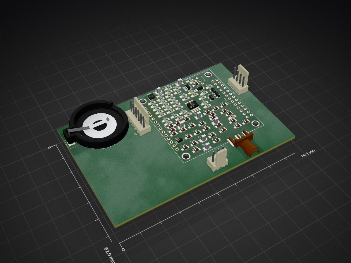
 antonjan/IQ_Modulator7
IQ Modulator for 2M and 70cm from I2C and ALSA PCM Audio on Orange PI Zero (Estimated TX Power 500mW)
Vhf uhf IQ Modulator is an open-source printed circuit board by antonjan, from the antonjan/IQ_Modulator repository on GitHub, published under the GPL-3.0 licence. It is a 2-layer board with 88 parts on 82 nets.
It is built around the MMZ09332BT1, PCF8563 and BC817-40. Its parts include 33 capacitors, 30 resistors, 9 inductors, 5 ICs and 5 connectors. It belongs with the radio and wireless and audio and music boards of this library.


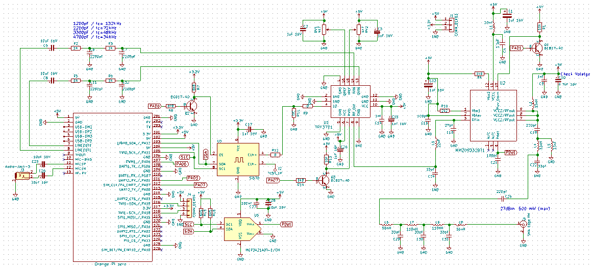
IQ Modulator for 2M generating IQ stream via Audio PCM codec as modelation and using I2C to controle the RF local oselator for the RF mixer. The modulated RF signal is the Amplified to about +27dbm. (estimated 500mW)
I2C Control for LO Local Osxelator with IQ moualtor RF amp and SAW and Ceremic output filters to antenna.
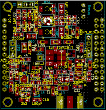
3d View
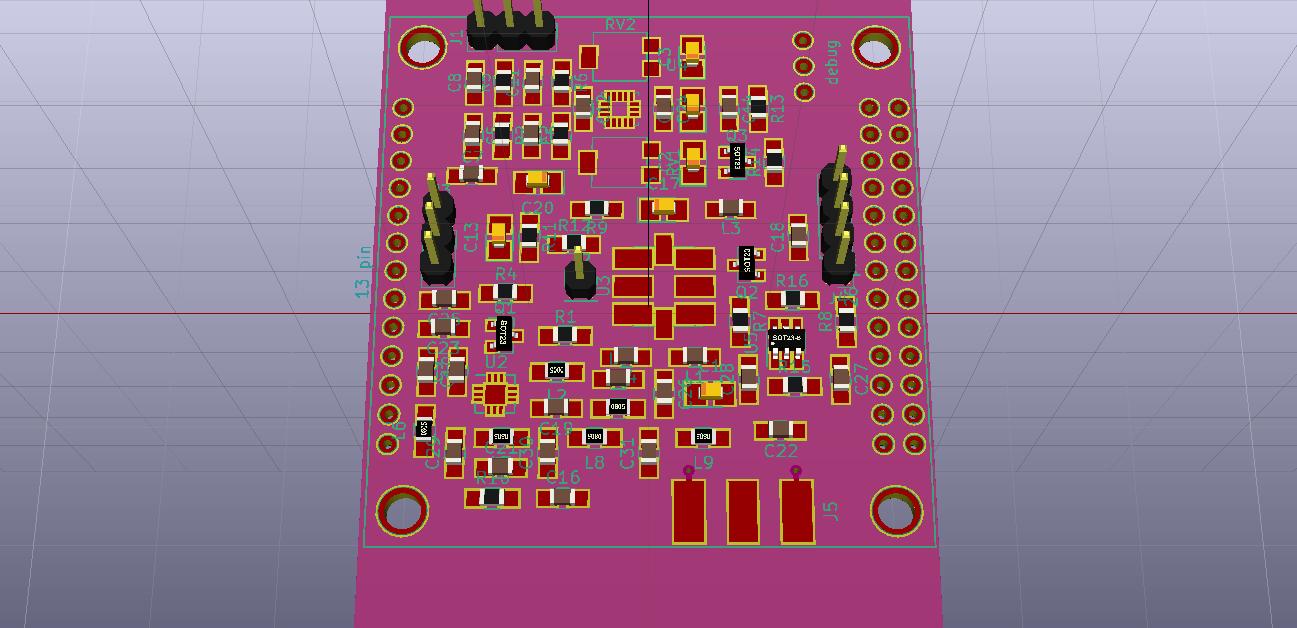
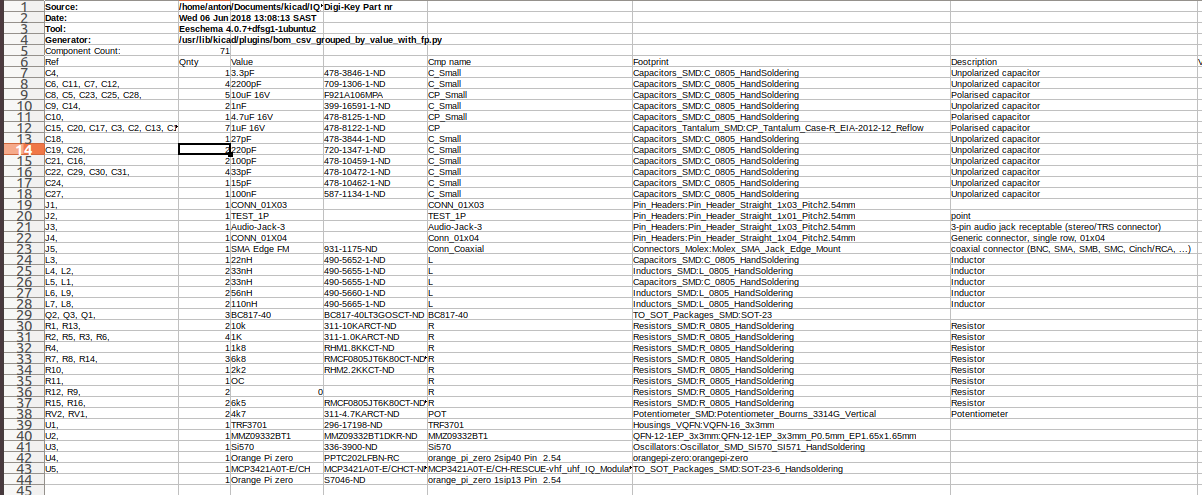
#Component list
I am considering using Orange Pi rather than Raspberry as it has build in Audio in and out with a smaller footprint
An another advantage of the Orange Pi is the additional USB ports witch I want to enable for the RTL dongle to be used as receiver.
The software concept was tested using gnuradio for transponder with a hackrf for TX and a rtl sdr dongle for RX.
I am still working on the telemetry witch works on its own but I need to combine it with Gnuraio transponder.
I have to telemetry modes at the moment CW send Calsign and cubesat name and settings. APRS 1200 FSK sending the status of transponder
Total power usage of board still needs to be calculated but my estimation with full power is 2w including Orange pi.
Power usage in sleep mode possibly 500mw
The PCB design was done in Kicad
This project is not compleet yet. (Almost done 12/06/2018)
My plan is to have it working by 15 July 2018.
The board V3 has the wrong pin configuration for U2 trf3701
I am now working on V4 ans need to get it working by 9 August 2018 for the BACAR6 baloon project.
The software for this Board will be in the following repository https://github.com/antonjan/Balloon-Transponder
| Qty | Value | Footprint | References |
|---|---|---|---|
| 8 | 0 | Resistors_SMD:R_0805_HandSoldering | R9, R12, R13, R15, R20, R21, R22, R23 |
| 7 | 1uF 16V | Capacitors_Tantalum_SMD:CP_Tantalum_Case-R_EIA-2012-12_Reflow | C1, C2, C3, C13, C15, C17, C20 |
| 5 | 10uF 16V | Capacitors_SMD:C_0805_HandSoldering | C5, C8, C23, C25, C27 |
| 4 | 1K | Resistors_SMD:R_0805_HandSoldering | R2, R3, R5, R6 |
| 4 | 2200pF | Capacitors_SMD:C_0805_HandSoldering | C6, C7, C11, C12 |
| 4 | 33pF | Capacitors_SMD:C_0805_HandSoldering | C22, C29, C30, C31 |
| 4 | 4k7 | Resistors_SMD:R_0805_HandSoldering | R27, R28, RV1, RV2 |
| 4 | OC | Resistors_SMD:R_0805_HandSoldering | R11, R16, R24, R25 |
| 3 | 6k8 | Resistors_SMD:R_0805_HandSoldering | R7, R8, R17 |
| 3 | BC817-40 | TO_SOT_Packages_SMD:SOT-23 | Q1, Q2, Q3 |
| 2 | 100nF | Capacitors_SMD:C_0805_HandSoldering | C26, C32 |
| 2 | 100pF | Capacitors_SMD:C_0805_HandSoldering | C16, C21 |
| 2 | 10k | Resistors_SMD:R_0805_HandSoldering | R1, R14 |
| 2 | 110nH | Inductors_SMD:L_0805_HandSoldering | L7, L8 |
| 2 | 1nF | Capacitors_SMD:C_0805_HandSoldering | C9, C14 |
| 2 | 220pF | Capacitors_SMD:C_0805_HandSoldering | C19, C28 |
| 2 | 33nF | Capacitors_SMD:C_0805_HandSoldering | L1, L5 |
| 2 | 33nH | Inductors_SMD:L_0805_HandSoldering | L2, L4 |
| 2 | 56nH | Inductors_SMD:L_0805_HandSoldering | L6, L9 |
| 2 | 6k5 | Resistors_SMD:R_0805_HandSoldering | R18, R19 |
| 1 | 15pF | Capacitors_SMD:C_0805_HandSoldering | C24 |
| 1 | 1N4148 | Diodes_SMD:D_SOD-123 | D1 |
| 1 | 1k8 | Resistors_SMD:R_0805_HandSoldering | R4 |
| 1 | 22nF | Capacitors_SMD:C_0805_HandSoldering | L3 |
| 1 | 22pF | Capacitors_SMD:C_0805_HandSoldering | C33 |
| 1 | 27pF | Capacitors_SMD:C_0805_HandSoldering | C18 |
| 1 | 2k2 | Resistors_SMD:R_0805_HandSoldering | R10 |
| 1 | 3.3V Battery_Cell | Battery_Holders:Keystone_103_1x20mm-CoinCell | BT1 |
| 1 | 3.3pF | Capacitors_SMD:C_0805_HandSoldering | C4 |
| 1 | 32.768Khz | Crystals:Crystal_SMD_G8-2pin_3.2x1.5mm_HandSoldering | Y1 |
| 1 | 4.7uF 16V | Capacitors_SMD:C_0805_HandSoldering | C10 |
| 1 | 56 | Resistors_SMD:R_0805_HandSoldering | R26 |
| 1 | Audio-Jack-3 | Connectors_Molex:Molex_KK-6410-03_03x2.54mm_Straight | J3 |
| 1 | CONN_01X04 | Connectors_Molex:Molex_KK-6410-04_04x2.54mm_Straight | J4 |
| 1 | Conn_01x06 | Connectors_Molex:Molex_KK-6410-06_06x2.54mm_Straight | J1 |
| 1 | MCP3421A0T-E/CH | TO_SOT_Packages_SMD:SOT-23-6_Handsoldering | U5 |
| 1 | MMZ09332BT1 | Resistors_SMD:R_0805_HandSoldering | U2 |
| 1 | Orange Pi zero | orangepi-zero:orangepi-zero | U4 |
| 1 | PCF8563 | Housing_SO8:SO-8 | U6 |
| 1 | SMA Edge FM | Connectors_Molex:Molex_SMA_Jack_Edge_Mount | J5 |
| 1 | TEST_1P | Inductors_SMD:L_0805_HandSoldering | J2 |
| 1 | TRF3701 | Housings_VQFN:VQFN-16_3x3mm | U1 |
antonjan/IQ_Modulator
IQ Modulator for 2M and 70cm from I2C and ALSA PCM Audio on Orange PI Zero (Estimated TX Power 500mW)


victor-chew/espclock3
Internet-enabled Analog Clock using ESP8266 and ATtiny85


r-map/rmap
rete monitoraggio ambientale partecipativo documentation at https://doc.rmap.cc


88 parts, built around the MMZ09332BT1, PCF8563 and BC817-40. The full list of its parts is on this page, with links to each part's symbol and footprint where PCBKit's library has them.
From the antonjan/IQ_Modulator repository on GitHub, at the commit this page was made from: the board is vhf_uhf_IQ_Modulator.kicad_pcb. PCBKit opens the board in the browser, with nothing to install.
Its repository publishes it under the GPL-3.0 licence: you may reuse it on that licence's terms (keep the author's notice, and for a copyleft licence share your changes alike).