
2 layers170 × 140 mm
LibreVerter Controller
imendizabal/LibreVerter
Open Source Power Converter - Hardware Components
215 parts22
 Anthilla/AnthC40
Anthilla AnthC Board
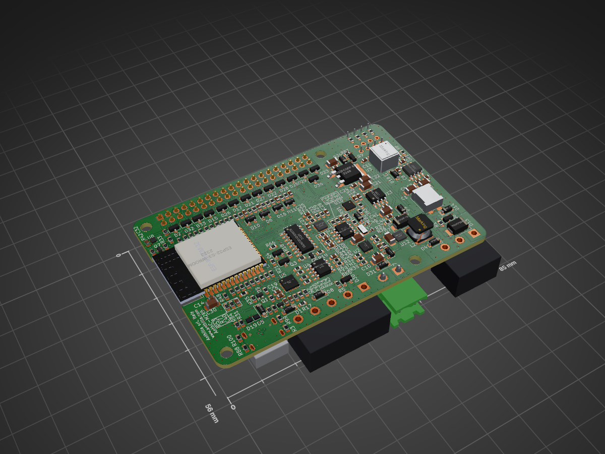
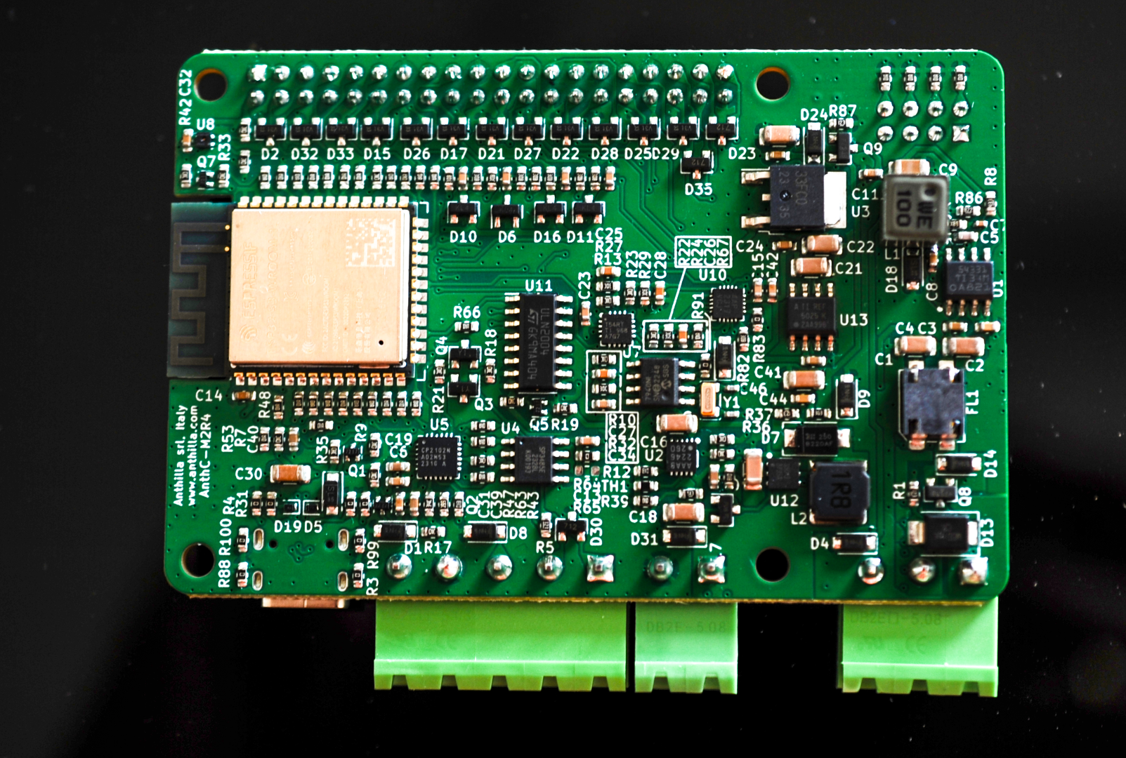
AnthC is an open-source printed circuit board by Anthilla, from the Anthilla/AnthC repository on GitHub. It is a 4-layer board of 85 × 56 mm with 211 parts on 173 nets, routed with 1,690 tracks and 518 vias.
It is built around the ESP32-S3-WROOM-1-N16, SP3485EN-L/TR and TLV9054ID, with the CP2102N-A02-GQFN24, LM2735XMF and SHT40-AD1B-R2 among its other parts. Its parts include 93 resistors, 44 capacitors, 33 diodes, 13 ICs and 9 transistors. It belongs with the ESP32 boards of this library.






AnthC (Anthilla Controller) is an ESP32-based controller for industrial and field IoT: read 4–20 mA sensors, talks RS485, switch loads, and keep running on battery when the supply drops. Raspberry Pi footprint, so it drops into existing enclosures and DIN-rail mounts.
Buy on Elecrow · Download M2-R5 files · Hackaday project · Design articles
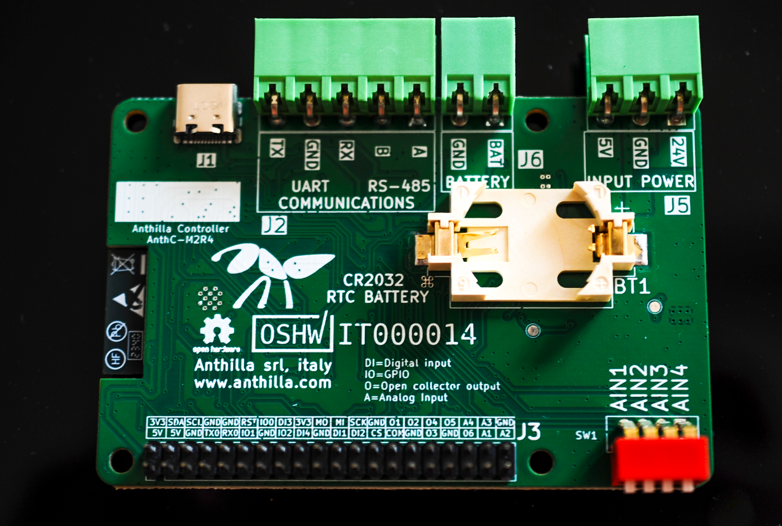
| MCU | ESP32-S3-WROOM-1: Dual-Core 32bit microprocessor. WiFi (802.11b/g/n) and Bluetooth. On board antenna |
| Power input | 7–28 V DC or 5 V direct through USB |
| Battery backup | Rechargeable LiPo, on-board charger |
| Digital inputs | 4 × Digital signals [0-3.3V] |
| Outputs | 6 × open collector (ULN2003), 500mA per channel |
| Analog inputs | 4 × 16-bit ADC, each switchable 0–5V V or 4–20 mA (multiplexed) |
| Fieldbus | RS485 half-duplex (SP3485EN). On-board termination |
| RTC | MCP7940N, CR2032 coin cell |
| Expansion | I2C, SPI |
| USB | USB-C (programming + 5 V power) |
| Form factor | Raspberry Pi footprint, 85 × 56 mm |
For manufacturing or evaluation, use the Releases — each hardware revision ships a fabrication zip (Gerbers, drill), an assembly zip (BOM with MPNs, placement), the schematic as PDF and a STEP model.
| Path | Content |
|---|---|
AnthC/ | KiCad project (requires KiCad 10 or later) and project libraries in AnthC/lib/ |
AnthC/Doc/Schematics/ | Schematic PDFs per revision |
AnthC/Doc/Manufacturing/ | Gerbers and drill files per revision (older revisions in Archive/) |
AnthC/Doc/Assembly/ | BOM and pick-and-place per revision |
AnthC/Doc/STEP/ | 3D models |
AnthC/Doc/Certifications/ | OSHWA certification marks |
Marketing/ | Logos and photos |
The revision is printed on the silkscreen (e.g. AnthC-M2R5).
| Revision | Status | Changes |
|---|---|---|
| M2-R5 | Current | USB-C fixed · ULN2004 replaced by ULN2003 |
| M2-R4 | Superseded · OSHWA IT000014 | Stackup Signal+Power / GND / GND / Signal+Power · Battery control: BJT replaced by MOSFET |
| M2-R3 | Superseded · OSHWA IT000013 | First certified release |
All About Circuits — Building and Certifying an Open-Source IoT Controller:
M2-R4 shown; M2-R5 is visually near-identical (They will be replaced)
| Qty | Value | Footprint | References |
|---|---|---|---|
| 32 | 100 | Resistor_SMD:R_0603_1608Metric | R25, R26, R28, R34, R48, R53, R54, R55, R56, R57, R58, R59, R60, R61, R62, R66 +16 |
| 19 | 100nF | Capacitor_SMD:C_0603_1608Metric | C4, C11, C13, C14, C15, C20, C23, C24, C29, C31, C32, C34, C35, C36, C37, C38 +3 |
| 18 | 10K | Resistor_SMD:R_0603_1608Metric | R6, R7, R10, R13, R14, R15, R16, R17, R19, R22, R23, R30, R33, R35, R42, R81 +2 |
| 12 | PESD3V3L2BT | Semiconductors:SOT-23 | D2, D15, D17, D21, D22, D25, D26, D27, D28, D29, D32, D33 |
| 10 | 0 | Resistor_SMD:R_0603_1608Metric | R3, R20, R31, R64, R65, R83, R88, R91, R99, R100 |
| 9 | 2KΩ | Resistor_SMD:R_0603_1608Metric | R40, R44, R45, R46, R49, R50, R51, R52, R82 |
| 8 | 10uF | Capacitor_SMD:C_1206_3216Metric | C1, C2, C16, C18, C21, C30, C41, C43 |
| 8 | Zener_6V | Semiconductors:D_SOD-123 | D1, D4, D8, D9, D14, D20, D24, D31 |
| 4 | 10nF | Capacitor_SMD:C_0603_1608Metric | C25, C26, C27, C28 |
| 4 | 1uF | Capacitor_SMD:C_0603_1608Metric | C17, C19, C39, C40 |
| 4 | 20K | Resistor_SMD:R_0603_1608Metric | R24, R27, R29, R32 |
| 4 | 2N7002T-7-F | Transistors:SOT-523 | Q1, Q2, Q5, Q7 |
| 4 | BAT54S | Package_TO_SOT_SMD:SOT-23 | D6, D10, D11, D16 |
| 4 | MH | MountingHole:MountingHole_3.2mm_M3 | MH1, MH2, MH3, MH4 |
| 3 | 10KΩ | Resistor_SMD:R_0603_1608Metric | R18, R21, R41 |
| 3 | 12K | Resistor_SMD:R_0603_1608Metric | R1, R37, R87 |
| 3 | 1K | Resistor_SMD:R_0603_1608Metric | R11, R12, R43 |
| 3 | 47uF | Capacitor_SMD:C_1206_3216Metric | C9, C12, C22 |
| 3 | TVS_2-Channel-7V | Semiconductors:SOT-23 | D23, D30, D35 |
| 2 | 5K1Ω | Resistor_SMD:R_0603_1608Metric | R68, R84 |
| 2 | 7pF | Capacitor_SMD:C_0402_1005Metric | C45, C46 |
| 2 | B5819W | Diode_SMD:D_SOD-123 | D3, D18 |
| 2 | MMSS8050-H-TP | Transistors:SOT-23 | Q3, Q4 |
| 2 | SI2347DS-T1-GE3 | Transistors:SOT-23 | Q8, Q9 |
| 2 | SP3205-01ETG | Semiconductors:D_SOD-882 | D5, D19 |
| 2 | TestPoint_1.5mm | TestPoint:TestPoint_Pad_D1.5mm | TP7, TP18 |
| 1 | 01x03 | Connectors:WURTH-691312510003 | J5 |
| 1 | 1.8μH-5.8A | Inductors:Inductor_Wurth_LQS-6045 | L2 |
| 1 | 100KΩ | Resistor_SMD:R_0603_1608Metric | R39 |
| 1 | 10μH-5A | Inductors:Inductor_Wurth_XHMI-6060 | L1 |
| 1 | 120 | Resistor_SMD:R_0603_1608Metric | R5 |
| 1 | 1nF | Capacitor_SMD:C_0603_1608Metric | C44 |
| 1 | 1x02 | Connectors:WURTH-691312510002 | J6 |
| 1 | 1x05 | Connectors:WURTH-691312510005 | J2 |
| 1 | 22K1 | Resistor_SMD:R_0603_1608Metric | R47 |
| 1 | 22nF | Capacitor_SMD:C_0603_1608Metric | C3 |
| 1 | 36KΩ | Resistor_SMD:R_0603_1608Metric | R36 |
| 1 | 4.7nF | Capacitor_SMD:C_0402_1005Metric | C7 |
| 1 | 43K | Resistor_SMD:R_0603_1608Metric | R8 |
| 1 | 47K5 | Resistor_SMD:R_0603_1608Metric | R63 |
| 1 | 47pF | Capacitor_SMD:C_0603_1608Metric | C5 |
| 1 | 49.9 | Resistor_SMD:R_0603_1608Metric | R2 |
| 1 | 51KΩ | Resistor_SMD:R_0603_1608Metric | R38 |
| 1 | 8.2KΩ | Resistor_SMD:R_0603_1608Metric | R86 |
| 1 | ACM7060-701-2PL-TL01 | Inductors:ChokeSMD_ACM7060 | FL1 |
| 1 | B220AF-13 | Diode_SMD:D_SMA | D7 |
| 1 | BD33FC0FP-E2 | IC:TO-252-2 | U3 |
| 1 | Battery_Cell_CR2032 | Connectors:BatteryHolder_WURTH_79527141-C_1x2032 | BT1 |
| 1 | CP2102N-A02-GQFN24 | Package_DFN_QFN:QFN-24-1EP_4x4mm_P0.5mm_EP2.6x2.6mm | U5 |
| 1 | Conn_02x20_Odd_Even | Connectors:PinHeader_2x20_P2.54mm_Vertical | J3 |
| 1 | DMN67D8L-7 | Transistors:SOT-23 | Q10 |
| 1 | ESP32-S3-WROOM | Processor:ESP32-S3-WROOM | U6 |
| 1 | LM2735X | IC:WSON-6-1EP_3x3mm_P0.95mm | U12 |
| 1 | LOGO | nodemcu:anthillaLogo9mm | G*** |
| 1 | MCP3464RT-E_NC | IC:UQFN-20-1EP_3x3mm_P0.4mm_EP1.85x1.85mm_ThermalVias | U10 |
| 1 | MCP73833-DFN | IC:DFN-10-1EP_3x3mm_P0.5mm_EP1.65x2.38mm_ThermalVias | U2 |
| 1 | MCP7940N-I/SN | IC:SOIC-8_3.9x4.9mm_P1.27mm | U7 |
| 1 | NTC_10K | Resistor_SMD:R_0603_1608Metric | TH1 |
| 1 | REF5025AID | Package_SO:SOIC-8_3.9x4.9mm_P1.27mm | U13 |
| 1 | SC32S | Crystal:Crystal_2pin_3.2mm_1.5mm | Y1 |
| 1 | SHT40-AD1B-R2 | IC:DFN-4 | U8 |
| 1 | SMBJ30CA | Semiconductors:D_SMB | D13 |
| 1 | SP3485EN-L/TR | Package_SO:SOIC-8_3.9x4.9mm_P1.27mm | U4 |
| 1 | SW_DIP_x04_Vertical | Electromechanical:SW_DIP_SPSTx04_Vertical_4_poles_P_2.54mm | SW1 |
| 1 | TLV9054 | IC:QFN-16-1EP_3x3mm_P0.5mm_EP1.7x1.7mm | U9 |
| 1 | TPS54331DR | Package_SO:SOIC-8-1EP_3.9x4.9mm_P1.27mm_EP2.29x3mm_ThermalVias | U1 |
| 1 | ULN2004D1013TR | IC:SO-16_3.9x9.9mm_P1.27mm | U11 |
| 1 | USB4105-GF-A | Connectors:USB4105-GF-A | J1 |
It measures 85 × 56 mm and has 4 copper layers, 1.6 mm thick.
211 parts, built around the ESP32-S3-WROOM-1-N16, SP3485EN-L/TR, TLV9054ID and CP2102N-A02-GQFN24. The full list of its parts is on this page, with links to each part's symbol and footprint where PCBKit's library has them.
From the Anthilla/AnthC repository on GitHub, at the commit this page was made from: the board is AnthC/AnthC.kicad_pcb and its schematic AnthC/AnthC.kicad_sch. PCBKit opens the board in the browser, with nothing to install.
Its repository states no licence, so its author keeps all rights: ask Anthilla before reusing the design.
imendizabal/LibreVerter
Open Source Power Converter - Hardware Components

rbala25/YerraGlasses
Audio Augmented Smart Glasses - ESP32, Hardware Build, System Integration, and Firmware (C)

lgugelmann/HD6301_thing
I recently received a few samples of a Hitachi HD6301V1 in a DIP-40 package. It's a 1MHz 8bit CPU derived from the Motorola 6801 with a few extra instructions.


KSullivan20221/SimHub-BMW-E46-Cluster-Module
This repo contains all of the circuitry, code, and resources used to create a shield board for an Arduino Mega that could be used to communicate with a BWM E46 instrument cluster from a PC.

HearnChristian/k-band-fmcw-radar
24 GHz FMCW radar front-end in KiCad (WIP): ADF4159 chirp synth, BGT24LTR11 transceiver, custom Marki AMM-8211PSM driver-amp symbol/footprint, OPA1656 IF, ADS8353 ADC, FT2232H USB.
