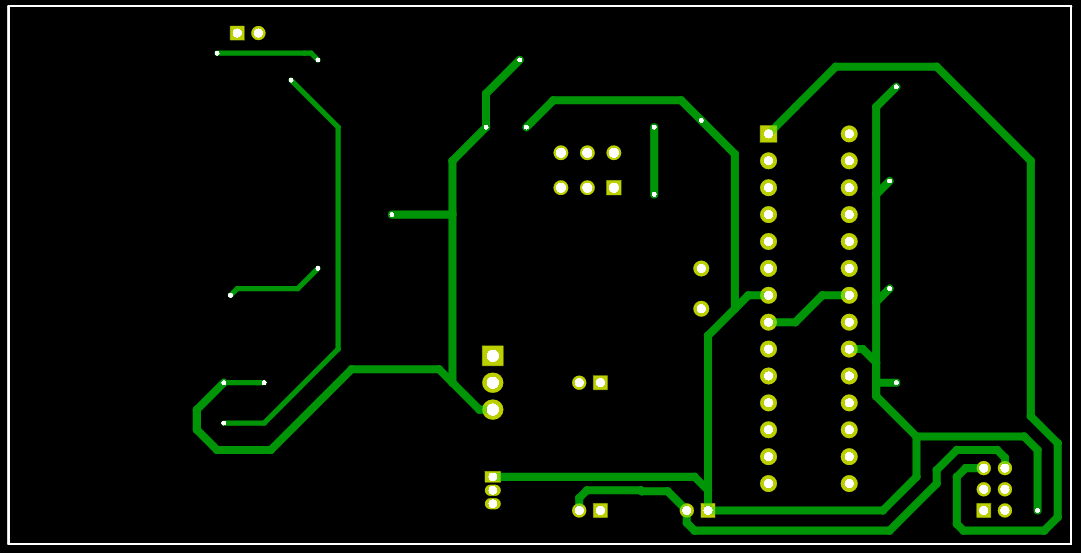
2 layers71.1 × 22.9 mm

 andre-fajar-n/Motor-Speed-Controller
Skill test for position Electrical Embedded Engineer in eFishery
PCB design is an open-source printed circuit board by andre-fajar-n, from the andre-fajar-n/Motor-Speed-Controller repository on GitHub. It is a 2-layer board with 46 parts on 52 nets, routed with 421 tracks and 20 vias.
It is built around the ATMEGA328-PU, ESP-WROOM-02 and BSS138, with the TIP122 among its other parts. Its parts include 14 resistors, 8 capacitors, 8 switches, 6 connectors and 4 ICs. It belongs with the interfaces and adapters boards and the AVR (ATmega, ATtiny) boards of this library.


This is my answer for job test for Electrical Embedded Engineer position from a company. The task is to make motor speed controller used ATMega 328, and trasnfer the data to ESP wroom 02 to save in microSD card and web server
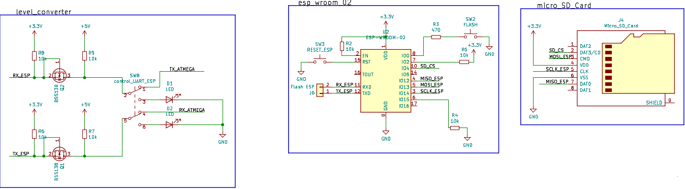
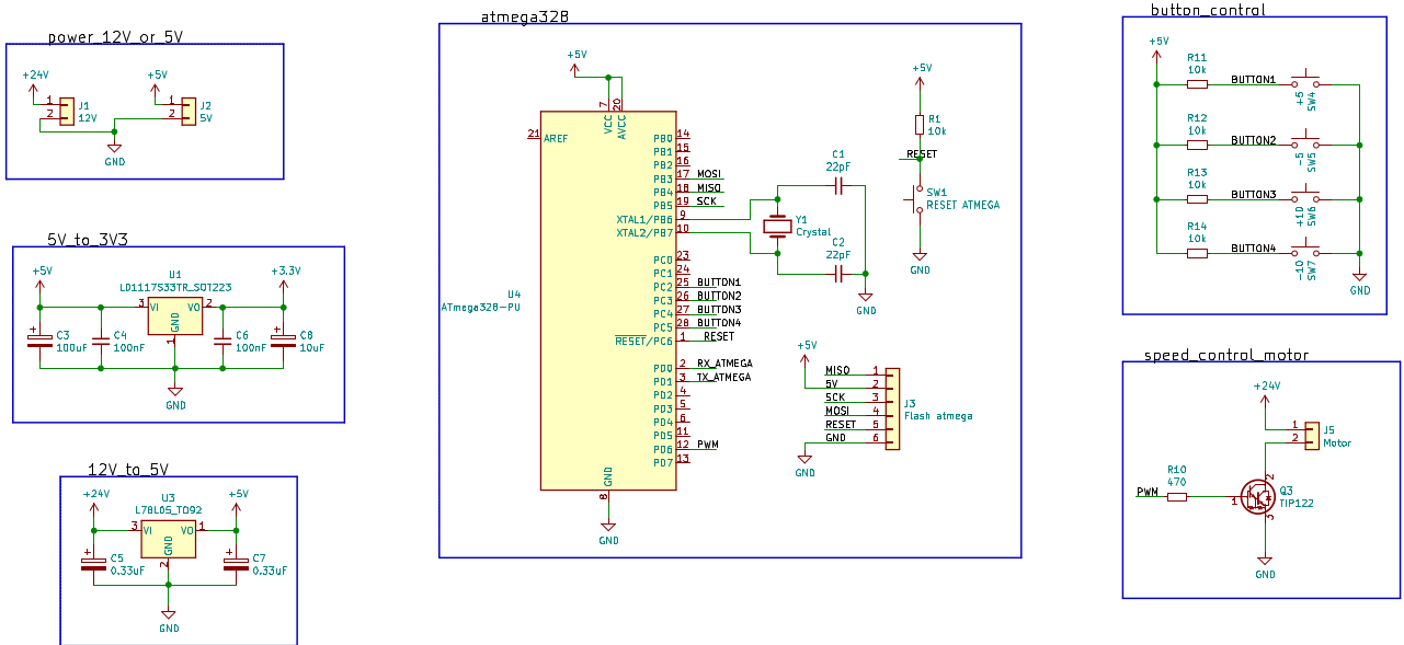 Or you can see the PDF in folder
Schematic
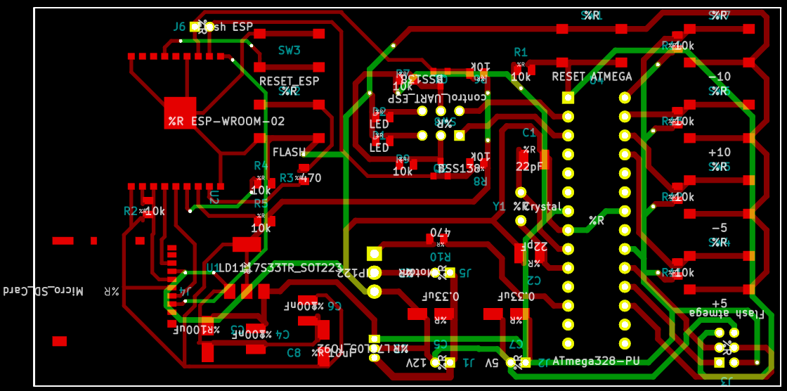
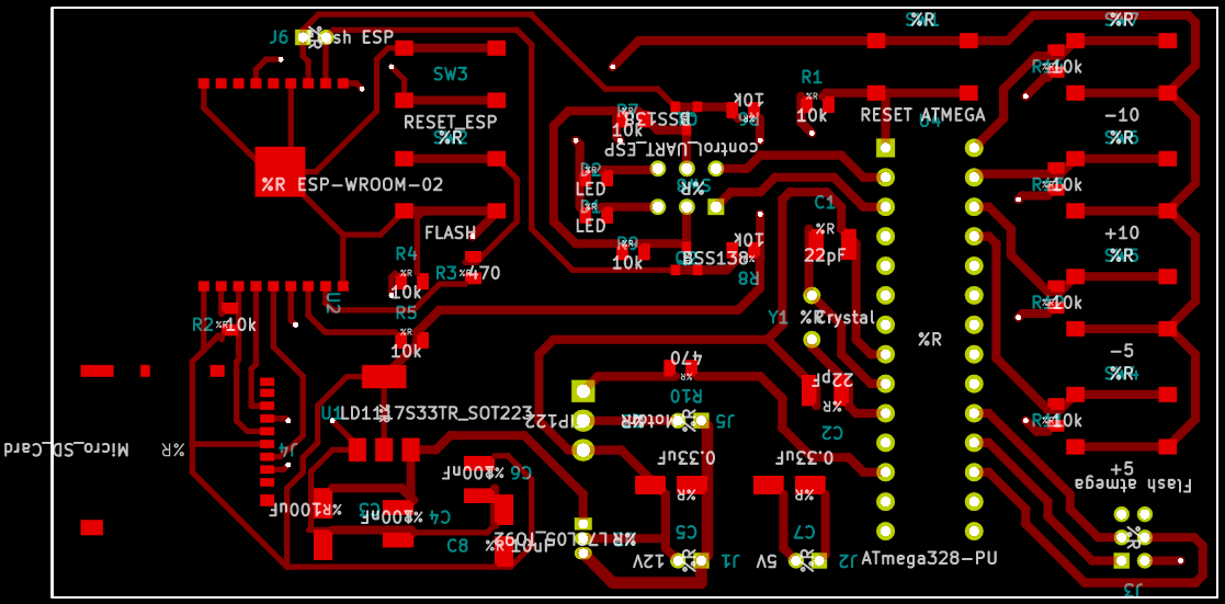
For firmware, I used Arduino programming to both of the microcontroller
| Qty | Value | Footprint | References |
|---|---|---|---|
| 12 | 10k | Resistor_SMD:R_0805_2012Metric | R1, R2, R4, R5, R6, R7, R8, R9, R11, R12, R13, R14 |
| 2 | 0.33uF | Capacitor_SMD:CP_Elec_4x4.5 | C5, C7 |
| 2 | 100nF | Capacitor_SMD:C_1210_3225Metric | C4, C6 |
| 2 | 22pF | Capacitor_SMD:C_1210_3225Metric | C1, C2 |
| 2 | 470 | Resistor_SMD:R_0805_2012Metric | R3, R10 |
| 2 | BSS138 | Package_TO_SOT_SMD:SOT-23 | Q1, Q2 |
| 2 | LED | LED_SMD:LED_0805_2012Metric | D1, D2 |
| 1 | +10 | Button_Switch_SMD:SW_Push_1P1T_NO_6x6mm_H9.5mm | SW6 |
| 1 | +5 | Button_Switch_SMD:SW_Push_1P1T_NO_6x6mm_H9.5mm | SW4 |
| 1 | -10 | Button_Switch_SMD:SW_Push_1P1T_NO_6x6mm_H9.5mm | SW7 |
| 1 | -5 | Button_Switch_SMD:SW_Push_1P1T_NO_6x6mm_H9.5mm | SW5 |
| 1 | 100uF | Capacitor_SMD:CP_Elec_4x4.5 | C3 |
| 1 | 10uF | Capacitor_SMD:CP_Elec_4x4.5 | C8 |
| 1 | 12V | Connector_PinSocket_2.00mm:PinSocket_1x02_P2.00mm_Vertical | J1 |
| 1 | 5V | Connector_PinSocket_2.00mm:PinSocket_1x02_P2.00mm_Vertical | J2 |
| 1 | ATmega328-PU | Package_DIP:DIP-28_W7.62mm | U4 |
| 1 | Crystal | Crystal:Crystal_HC52-6mm_Vertical | Y1 |
| 1 | ESP-WROOM-02 | RF_Module:ESP-WROOM-02 | U2 |
| 1 | FLASH | Button_Switch_SMD:SW_Push_1P1T_NO_6x6mm_H9.5mm | SW2 |
| 1 | Flash ESP | Connector_PinHeader_2.00mm:PinHeader_1x02_P2.00mm_Vertical | J6 |
| 1 | Flash atmega | Connector_PinSocket_2.00mm:PinSocket_2x03_P2.00mm_Vertical | J3 |
| 1 | L78L05_TO92 | Package_TO_SOT_THT:TO-92_Inline | U3 |
| 1 | LD1117S33TR_SOT223 | Package_TO_SOT_SMD:SOT-223-3_TabPin2 | U1 |
| 1 | Micro_SD_Card | Connector_Card:microSD_HC_Hirose_DM3AT-SF-PEJM5 | J4 |
| 1 | Motor | Connector_PinHeader_2.00mm:PinHeader_1x02_P2.00mm_Vertical | J5 |
| 1 | RESET ATMEGA | Button_Switch_SMD:SW_Push_1P1T_NO_6x6mm_H9.5mm | SW1 |
| 1 | RESET_ESP | Button_Switch_SMD:SW_Push_1P1T_NO_6x6mm_H9.5mm | SW3 |
| 1 | TIP122 | Package_TO_SOT_THT:TO-220-3_Vertical | Q3 |
| 1 | control_UART_ESP | Button_Switch_THT:SW_CuK_JS202011CQN_DPDT_Straight | SW8 |

PhysicsUofRAUI/hooting_owl
Hold code and eventually the pcb layout for my hooting owl retrofit

cclienti/tig-welder
A DIY TIG welder that can be plugged to a traditionnal stick welder or to a high current source


embeddedos-org/eCAD-Hardware-Products
Hardware designs + EE docs + Board datasheets of Multiple products


46 parts, built around the ATMEGA328-PU, ESP-WROOM-02, BSS138 and TIP122. The full list of its parts is on this page, with links to each part's symbol and footprint where PCBKit's library has them.
From the andre-fajar-n/Motor-Speed-Controller repository on GitHub, at the commit this page was made from: the board is PCB/PCB design.kicad_pcb. PCBKit opens the board in the browser, with nothing to install.
Its repository states no licence, so its author keeps all rights: ask andre-fajar-n before reusing the design.