2 layers85 × 56 mm

 an-ven/graspib14
GPIB interface board for Raspberry Pi
GrasPiB v1 is an open-source printed circuit board by an-ven, from the an-ven/graspib repository on GitHub. It is a 2-layer board of 85 × 56 mm with 45 parts on 78 nets, routed with 760 tracks and 74 vias.
It is built around the MAX3232ID, SN75160BDW and SN75161BDW, with the LM2576S-5.0 and SBRT5A50SA-13-FS among its other parts. Its parts include 9 capacitors, 6 connectors, 5 resistors, 5 ICs and 3 diodes. It belongs with the computers and single-board computers and interfaces and adapters boards of this library.


A simple adapter board for connecting the GrasPiB Raspberry Pi hat to an Arduino Micro running the AR488 firmware.
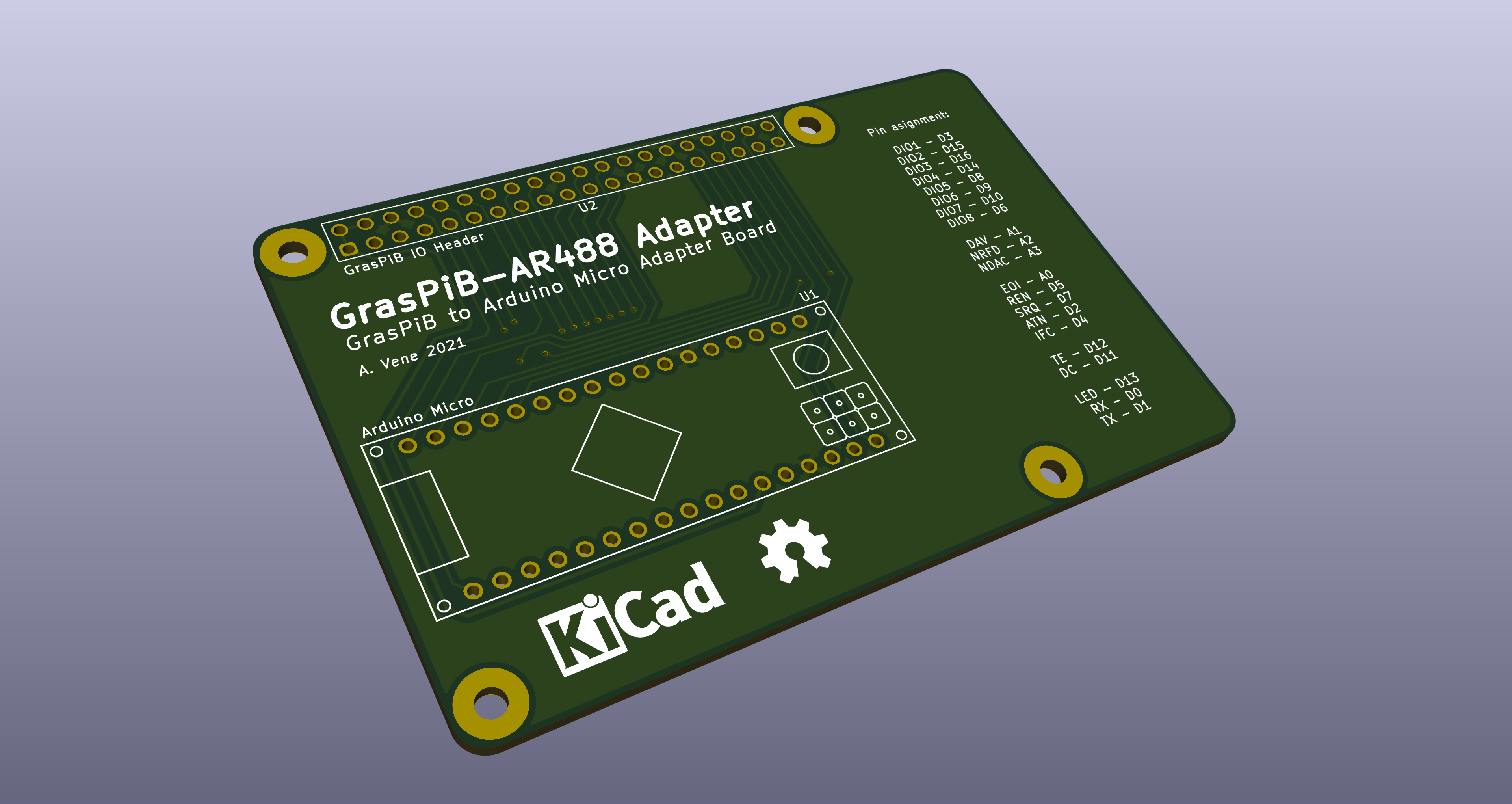
Pin assignment is compatible with the default AR488, except for the TE and DC control signals for the SN7516x bus drivers, which need to be enabled in the AR488_Config.h file.
In the AR488_Config.h config file, search for the Enable SN7516x chips section and modify it as follows:
/***** Enable SN7516x chips *****/
/*
 * Uncomment to enable the use of SN7516x GPIB tranceiver ICs.
 * This will require the use of an additional GPIO pin to control
 * the read and write modes of the ICs.
 */
#define SN7516X
#ifdef SN7516X
  #define SN7516X_TE 12
  #define SN7516X_DC 11
  //#define SN7516X_SC 12
#endif
No other modifications should be needed to use GrasPiB with an Arduino and AR488 software.
GrasPiB - AR488

   DIO1 - D3
   DIO2 - D15
   DIO3 - D16
   DIO4 - D14
   DIO5 - D8
   DIO6 - D9
   DIO7 - D10
   DIO8 - D6

    DAV - A1
   NRFD - A2
   NDAC - A3

    EOI - A0
    REN - D5
    SRQ - D7
    ATN - D2
    IFC - D4

     TE - D12
     DC - D11
| Qty | Value | Footprint | References |
|---|---|---|---|
| 4 | 100 | Resistor_SMD:R_Array_Convex_4x1206 | RN1, RN2, RN3, RN4 |
| 4 | 100nF | Capacitor_SMD:C_0603_1608Metric_Pad1.08x0.95mm_HandSolder | C1, C2, C6, C7 |
| 3 | 10k | Resistor_SMD:R_0603_1608Metric_Pad0.98x0.95mm_HandSolder | R3, R4, R5 |
| 3 | 470nF | Capacitor_SMD:C_0603_1608Metric_Pad1.08x0.95mm_HandSolder | C3, C4, C5 |
| 3 | M2,5 | MountingHole:MountingHole_2.7mm_M2.5 | H1, H2, H3 |
| 2 | CTS_EN | Jumper:SolderJumper-2_P1.3mm_Open_RoundedPad1.0x1.5mm | JP2, JP4 |
| 2 | RTS_EN | Jumper:SolderJumper-2_P1.3mm_Open_RoundedPad1.0x1.5mm | JP1, JP5 |
| 1 | 1000uF 10V | Capacitor_SMD:CP_Elec_10x10 | C9 |
| 1 | 100uF 35V | Capacitor_SMD:CP_Elec_10x10 | C8 |
| 1 | 100uH | Inductor_SMD:L_Wuerth_WE-PD-Typ-LS | L1 |
| 1 | 10pin IDC | Connector_IDC:IDC-Header_2x05_P2.54mm_Vertical | J6 |
| 1 | 3,5mm Pitch | TerminalBlock_Phoenix:TerminalBlock_Phoenix_PT-1,5-2-3.5-H_1x02_P3.50mm_Horizontal | J5 |
| 1 | 330 | Resistor_SMD:R_0603_1608Metric_Pad0.98x0.95mm_HandSolder | R1 |
| 1 | 430 | Resistor_SMD:R_0603_1608Metric_Pad0.98x0.95mm_HandSolder | R2 |
| 1 | Conn_GPIB | Connector_GPIB:NorComp_112-024-213R001 | J2 |
| 1 | DB9_Male | Connector_Dsub:DSUB-9_Male_Horizontal_P2.77x2.84mm_EdgePinOffset7.70mm_Housed_MountingHolesOffset9.12mm | J1 |
| 1 | DIO3_RT | Jumper:SolderJumper-3_P1.3mm_Bridged12_RoundedPad1.0x1.5mm | JP3 |
| 1 | Green | LED_SMD:LED_0603_1608Metric_Pad1.05x0.95mm_HandSolder | D2 |
| 1 | JST_PH | Connector_JST:JST_PH_B5B-PH-K_1x05_P2.00mm_Vertical | J4 |
| 1 | JST_PH | Connector_JST:JST_PH_B2B-PH-K_1x02_P2.00mm_Vertical | J3 |
| 1 | LM2576S-5 | Package_TO_SOT_SMD:TO-263-5_TabPin3 | U5 |
| 1 | MAX3232 | Package_SO:SO-16_3.9x9.9mm_P1.27mm | U2 |
| 1 | PWR SEL | Connector_PinHeader_2.54mm:PinHeader_1x03_P2.54mm_Vertical | JP7 |
| 1 | RPi_GPIO | RaspberryPi:RPi4_Hat | U1 |
| 1 | SBRT5A50SA-13 | Diode_SMD:D_SMA_Handsoldering | D3 |
| 1 | SN75160BDW | Package_SO:SO-20_12.8x7.5mm_P1.27mm | U3 |
| 1 | SN75161BDW | Package_SO:SO-20_12.8x7.5mm_P1.27mm | U4 |
| 1 | V_Sel | Jumper:SolderJumper-3_P1.3mm_Open_RoundedPad1.0x1.5mm | JP6 |
| 1 | Yellow | LED_SMD:LED_0603_1608Metric_Pad1.05x0.95mm_HandSolder | D1 |
The 43 most common of 45 parts.

fachat/csa_cbmio
IO Board for CS/A bus, to implement Commodore B-Series I/O

tridentsx/tmc-gateway
TinyGo firmware for an RP2350-based USB/PoE-LAN instrument gateway: bridges USBTMC/USB488 and HiSLIP to GPIB

achihuahua22/Alex-Harris-Capstone
This project builds on an-ven’s graspib project by adding more RS232 support and a UART breakout pin.


douardda/ESP32-GPIB-pcb
GitHub mirror of the PCB design for an ESP32/Arduino based GPIB interface

joseluu/MCP-AR-488-ESP32
The idea is to have AI help me build electronics. AI needs eyes, the eyes are the oscilloscope which is used through an MCP interface.


FL0WL0W/ESP32C3-CAN-Extender
This module uses an ESP32C3 with WiFi and BLE. It has 3 configurable outputs (5V push pull, Open Drain, 12V pullup), 4 analog or digital inputs, CAN transceiver, and an automotive power supply so it can be installed…
It measures 85 × 56 mm and has 2 copper layers, 1.6 mm thick.
45 parts, built around the MAX3232ID, SN75160BDW, SN75161BDW and LM2576S-5.0. The full list of its parts is on this page, with links to each part's symbol and footprint where PCBKit's library has them.
From the an-ven/graspib repository on GitHub, at the commit this page was made from: the board is GrasPiB_v1.kicad_pcb and its schematic GrasPiB_AR488_Adapter/GrasPiB_AR488_Adapter.kicad_sch. PCBKit opens the board in the browser, with nothing to install.
Its repository states no licence, so its author keeps all rights: ask an-ven before reusing the design.