
2 layers204.5 × 113 mm

Flexible programmable DC constant current/power load using Arduin Nano & custom PCB
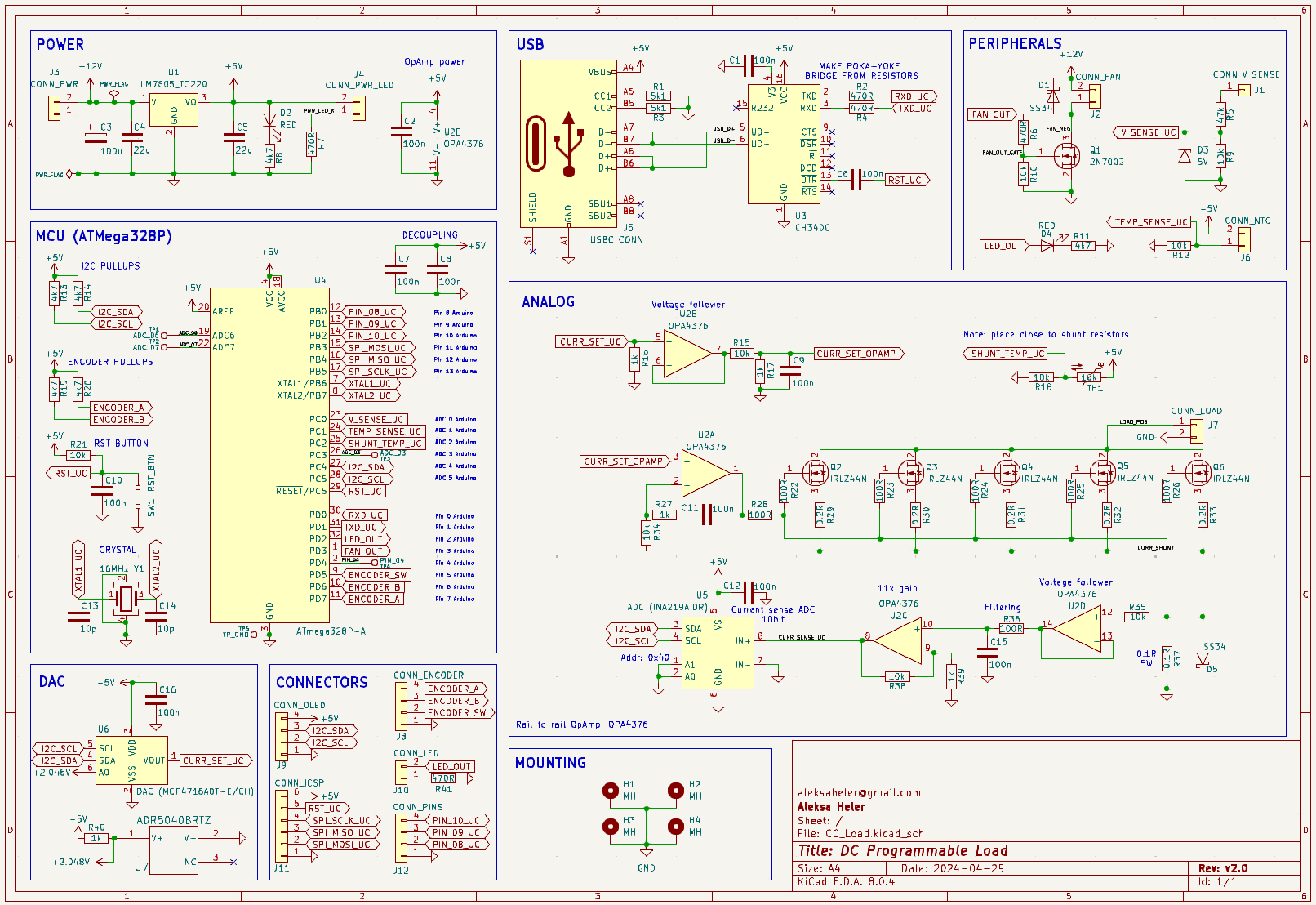
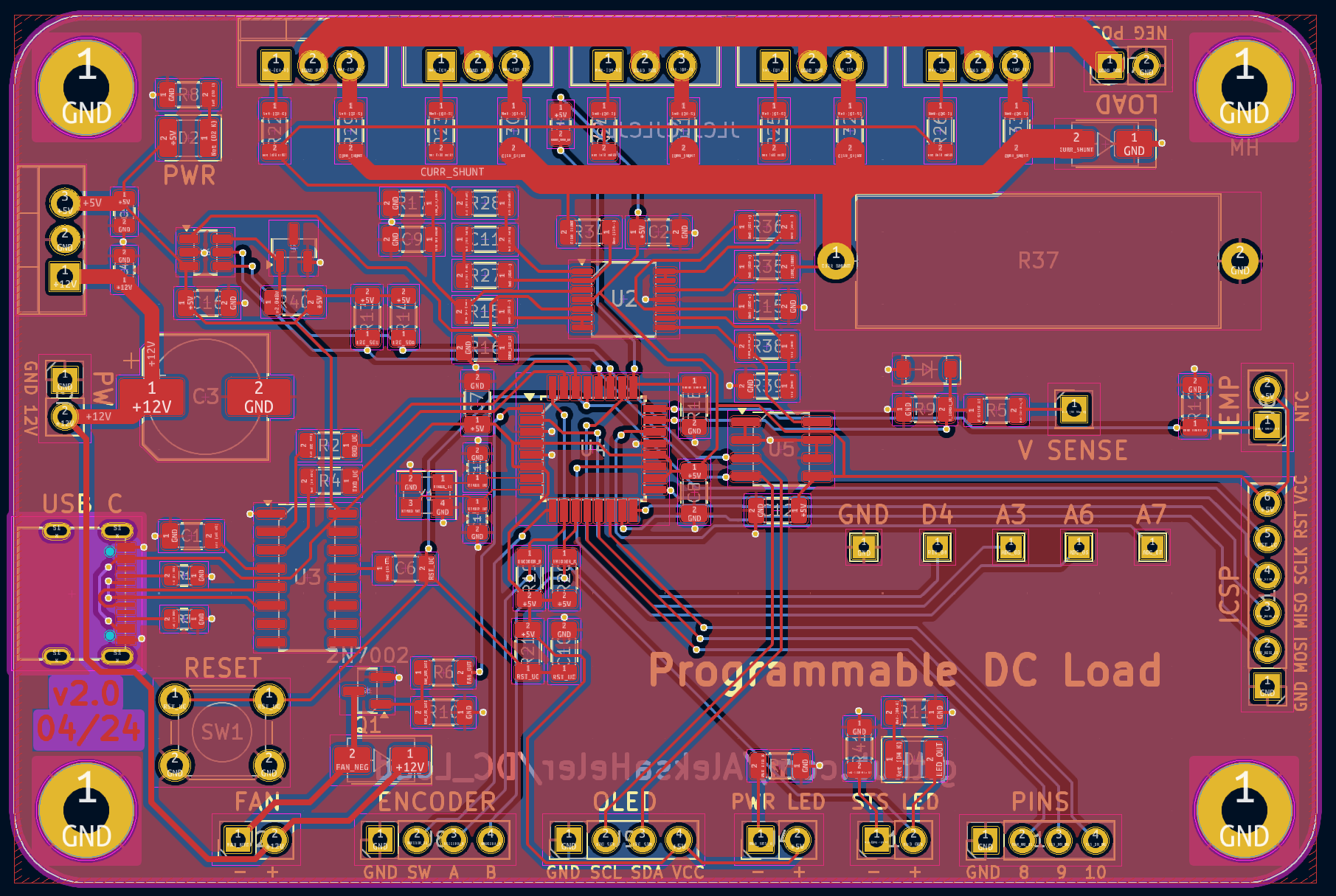
CC Load is an open-source printed circuit board by AleksaHeler, from the AleksaHeler/Programmable-DC-Load repository on GitHub, published under the MIT licence. It is a 2-layer board of 90 × 60 mm with 105 parts on 85 nets, routed with 725 tracks and 89 vias.
It is built around the ATMEGA328P-AU, CH340C and IRLZ44N, with the SS34 among its other parts. Its parts include 43 resistors, 18 capacitors, 14 connectors, 7 ICs and 6 diodes. It belongs with the AVR (ATmega, ATtiny) boards of this library.


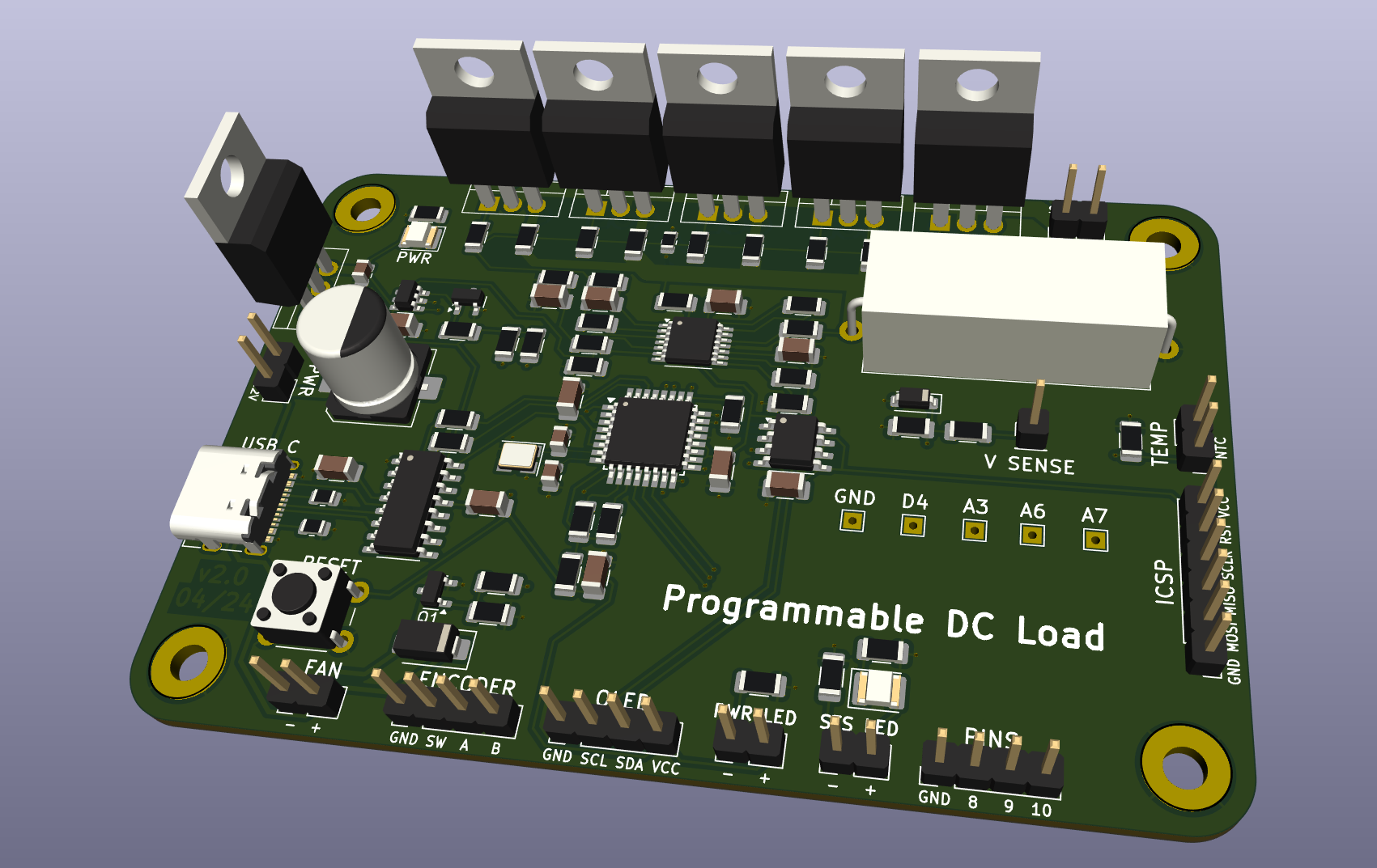
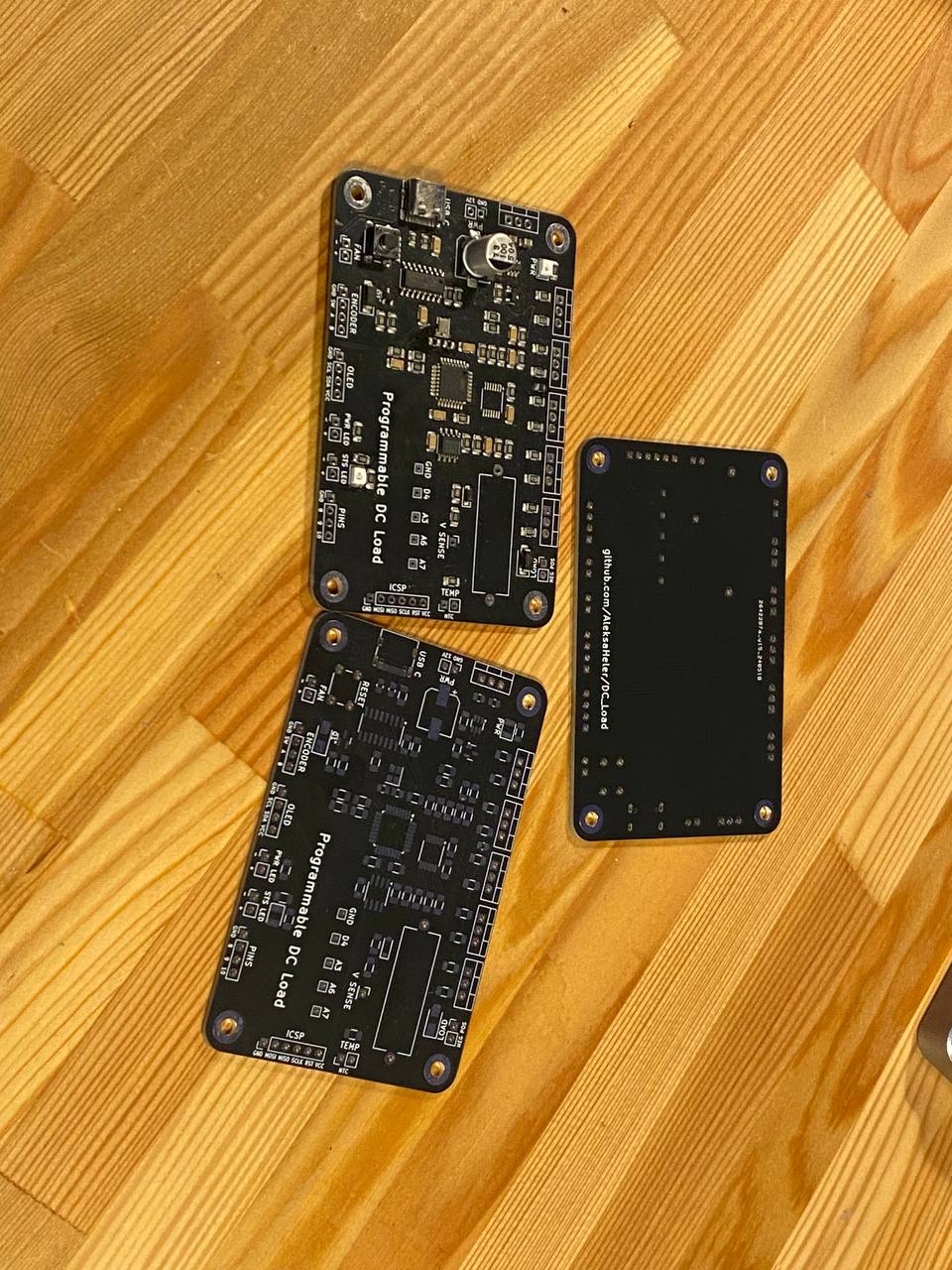
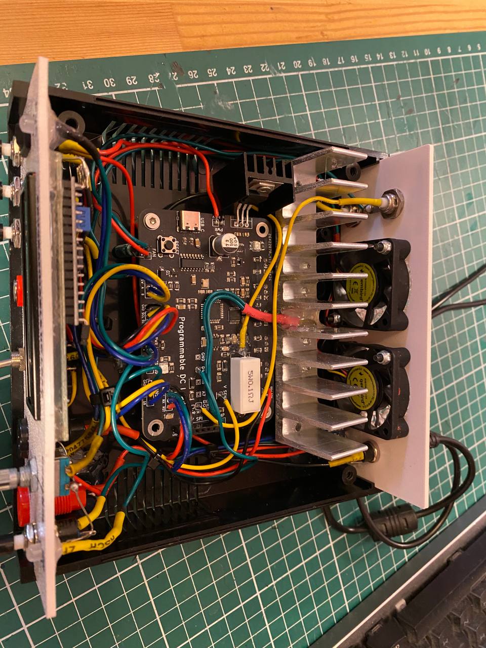
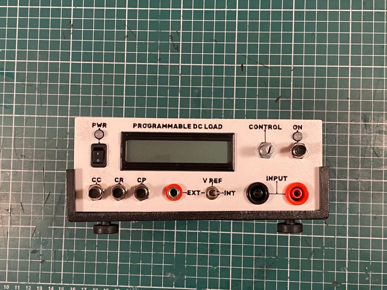
Flexible programmable DC constant current/power load using Arduin Nano and a custom PCB.
Following some ideas from this YouTube playlist from Scullcom Hobby Electronics.
If you just want the same ones as used in a standard Arduino, you can find them in the boards.txt file:
uno.bootloader.low_fuses=0xff
uno.bootloader.high_fuses=0xde
uno.bootloader.extended_fuses=0x05
We will be using another Arduino as ISP, so we should first program it with given example code, then we can use avrdude option 'avrisp', and use the port number of that device. We can read the fuses, and check if conncections are ok with:
.\utils\avrdude-v8.0\avrdude.exe -c avrisp -p m328p -P com23 -b 19200 -U lfuse:r:-:i -U hfuse:r:-:i -U efuse:r:-:i -vSo for these default settings we would use the following command:
.\utils\avrdude-v8.0\avrdude.exe -c avrisp -p m328p -P com23 -b 19200 -U lfuse:w:0xFF:m -U hfuse:w:0xDE:m -U efuse:w:0x05:m -vWhere:
  -c <programmer>                          Specify programmer type.
  -p <partno>                              Required. Specify AVR device.
  -P <port>                                Specify connection port.
  -b <baudrate>                            Override RS-232 baud rate.
  -U <memtype>:r|w|v:<filename>[:format]   Memory operation specification.
  -v                                       Verbose output. -v -v for more.
More options info can be found here.
To burn the bootloader, we will also be using Arduino as ISP, and in Arduino software just select burn bootloader after we select the board as Arduino Uno.
???
| Qty | Value | Footprint | References |
|---|---|---|---|
| 13 | 100n | Capacitor_SMD:C_1206_3216Metric | C1, C2, C6, C7, C8, C9, C10, C11, C12, C15, C16, C17, C18 |
| 10 | 10k | Resistor_SMD:R_1206_3216Metric | R8, R10, R12, R15, R16, R21, R34, R35, R39, R42 |
| 7 | 100R | Resistor_SMD:R_1206_3216Metric | R22, R23, R24, R25, R26, R28, R36 |
| 6 | 4k7 | Resistor_SMD:R_1206_3216Metric | R9, R11, R13, R14, R19, R20 |
| 5 | 0.2R | Resistor_SMD:R_1206_3216Metric | R29, R30, R31, R32, R33 |
| 5 | 1k | Resistor_SMD:R_1206_3216Metric | R17, R18, R27, R40, R43 |
| 5 | IRLZ44N | Package_TO_SOT_THT:TO-220-3_Vertical | Q2, Q3, Q4, Q5, Q6 |
| 4 | MH | MountingHole:MountingHole_3.2mm_M3_Pad | H1, H2, H3, H4 |
| 3 | 470R | Resistor_SMD:R_1206_3216Metric | R6, R7, R41 |
| 2 | 0R | Resistor_SMD:R_1206_3216Metric | R2, R4 |
| 2 | 20p | Capacitor_SMD:C_0805_2012Metric | C13, C14 |
| 2 | 22u | Capacitor_SMD:C_0805_2012Metric | C4, C5 |
| 2 | 5V | Diode_SMD:D_SOD-123 | D3, D6 |
| 2 | 5k1 | Resistor_SMD:R_0805_2012Metric | R1, R3 |
| 2 | RED | LED_SMD:LED_1210_3225Metric | D2, D4 |
| 2 | SS34 | Diode_SMD:D_SMA | D1, D5 |
| 1 | 0.1R | Resistor_THT:R_Axial_Power_L25.0mm_W9.0mm_P27.94mm | R37 |
| 1 | 100k | Resistor_SMD:R_1206_3216Metric | R38 |
| 1 | 100u | Capacitor_SMD:CP_Elec_8x10.5 | C3 |
| 1 | 10k | Resistor_SMD:R_0805_2012Metric | TH1 |
| 1 | 16MHz | Crystal:Crystal_SMD_3225-4Pin_3.2x2.5mm | Y1 |
| 1 | 2N7002 | Package_TO_SOT_SMD:SOT-23 | Q1 |
| 1 | 47k | Resistor_SMD:R_1206_3216Metric | R5 |
| 1 | ADC (INA219AIDR) | Package_SO:SOIC-8_3.9x4.9mm_P1.27mm | U5 |
| 1 | ADC_06 | TestPoint:TestPoint_THTPad_1.5x1.5mm_Drill0.7mm | TP1 |
| 1 | ADC_07 | TestPoint:TestPoint_THTPad_1.5x1.5mm_Drill0.7mm | TP2 |
| 1 | ADR5040BRTZ | Package_TO_SOT_SMD:SOT-23 | U7 |
| 1 | ATmega328P-A | Package_QFP:TQFP-32_7x7mm_P0.8mm | U4 |
| 1 | CH340C | Package_SO:SOIC-16_3.9x9.9mm_P1.27mm | U3 |
| 1 | CONN_ENCODER | Connector_PinHeader_2.54mm:PinHeader_1x04_P2.54mm_Vertical | J8 |
| 1 | CONN_EXT_CURR_SET | Connector_PinHeader_2.54mm:PinHeader_1x02_P2.54mm_Vertical | J14 |
| 1 | CONN_FAN | Connector_PinHeader_2.54mm:PinHeader_1x02_P2.54mm_Vertical | J2 |
| 1 | CONN_ICSP_SPI | Connector_PinHeader_2.54mm:PinHeader_1x06_P2.54mm_Vertical | J12 |
| 1 | CONN_LED | Connector_PinHeader_2.54mm:PinHeader_1x02_P2.54mm_Vertical | J10 |
| 1 | CONN_LOAD | Connector_PinHeader_2.54mm:PinHeader_1x02_P2.54mm_Vertical | J7 |
| 1 | CONN_NTC | Connector_PinHeader_2.54mm:PinHeader_1x02_P2.54mm_Vertical | J6 |
| 1 | CONN_OLED | Connector_PinHeader_2.54mm:PinHeader_1x04_P2.54mm_Vertical | J9 |
| 1 | CONN_PINS | Connector_PinHeader_2.54mm:PinHeader_1x04_P2.54mm_Vertical | J13 |
| 1 | CONN_PWR | Connector_PinHeader_2.54mm:PinHeader_1x02_P2.54mm_Vertical | J3 |
| 1 | CONN_PWR_LED | Connector_PinHeader_2.54mm:PinHeader_1x02_P2.54mm_Vertical | J4 |
| 1 | CONN_UART | Connector_PinHeader_2.54mm:PinHeader_1x04_P2.54mm_Vertical | J11 |
| 1 | CONN_USBC | Connector_USB:USB_C_Receptacle_G-Switch_GT-USB-7010ASV | J5 |
| 1 | CONN_V_SENSE | Connector_PinHeader_2.54mm:PinHeader_1x01_P2.54mm_Vertical | J1 |
| 1 | DAC (MCP4716A0T-E/CH) | Package_TO_SOT_SMD:SOT-23-6 | U6 |
| 1 | LM7805_TO220 | Package_TO_SOT_THT:TO-220-3_Vertical | U1 |
| 1 | OPA4376 | Package_SO:TSSOP-14_4.4x5mm_P0.65mm | U2 |
| 1 | PIN_04 | TestPoint:TestPoint_THTPad_1.5x1.5mm_Drill0.7mm | TP3 |
| 1 | RST_BTN | Button_Switch_THT:SW_PUSH_6mm | SW1 |
| 1 | TP_GND | TestPoint:TestPoint_THTPad_1.5x1.5mm_Drill0.7mm | TP4 |
It measures 90 × 60 mm and has 2 copper layers, 1.6 mm thick.
105 parts, built around the ATMEGA328P-AU, CH340C, IRLZ44N and SS34. The full list of its parts is on this page, with links to each part's symbol and footprint where PCBKit's library has them.
From the AleksaHeler/Programmable-DC-Load repository on GitHub, at the commit this page was made from: the board is DC_Load_KiCAD/CC_Load.kicad_pcb and its schematic DC_Load_KiCAD/CC_Load.kicad_sch. PCBKit opens the board in the browser, with nothing to install.
Its repository publishes it under the MIT licence: you may reuse it on that licence's terms (keep the author's notice, and for a copyleft licence share your changes alike).

vadymtaranenko/ESP32-3S-BMS
Prosty, niezawodny system zarządzania pakietami Li-Po 3S oparty na mikrokontrolerze ESP32. Układ komunikuje się po magistrali SPI.


HeyPCB/whisker
Drop-in controller for Petoi's Nybble robot cat running the stock OpenCat firmware: ATmega328P, PCA9685, MPU-6050, USB-C, 3 A buck, protected battery input. 4-layer KiCad 10 board plus printed cradle.

adeboni/eurorack
This repository stores various eurorack module designs I've made


tpanajott/DMX512_LedDimmer
Wireless DMX512 controller with remote LED driver boards
