
2 layers36 × 20 mm

 adamb314/ServoProject545
Getting the most out of your hobby servo
OpticalEncoder is an open-source printed circuit board by adamb314, from the adamb314/ServoProject repository on GitHub. It is a 2-layer board of 9 × 3.6 mm with 6 parts on 6 nets.
It is built around the ITR8307. Its parts include 4 resistors and 2 ICs. It belongs with the robots and motor control boards of this library.
by Adam Bäckström
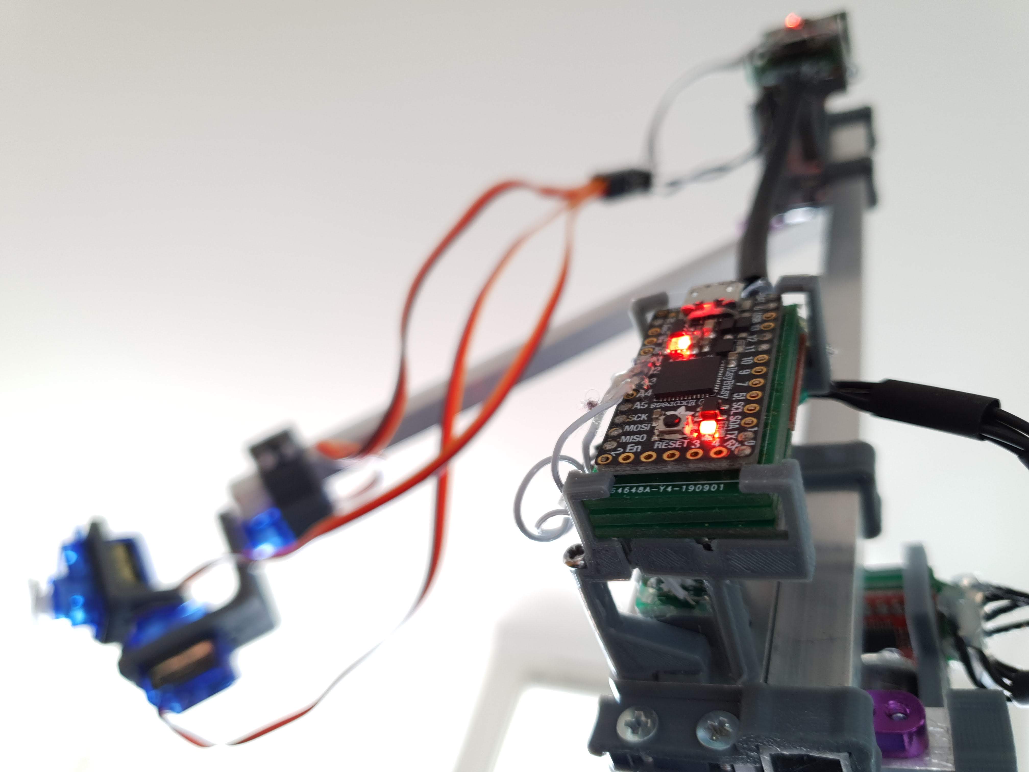
This folder contains the Arduino project for the Adafruit ItsyBitsy M0 Express boards.
Easiest way to program and configure the servos is through the configurationWizard.py script.
Just run python3 ./ArduinoSketch/configurationWizard.py to get started. The script will ask if it should install any missing dependencies.
PLEASE NOTE! Windows users must use MSYS2 due to the the PyGObject package, see https://pygobject.readthedocs.io/en/latest/getting_started.html. After installing MSYS2 run the script with:
C:\msys64\mingw64\bin\python.exe ArduinoSketch\configurationWizard.pyWhen compiling, the active configuration is selected by modifying the #include "*.h" line in the config/config.h file to include the desired config file. The configSelector.py script can be used to simplify the config selecting process by giving a drop-down list with all configs in the config folder.
The folder also holds a Makefile which can be used to compile and transfer the project. One benefit of using the Makefile is that the configSelector script is always executed prior to compiling. To be able to use the Makefile you must first install arduino-cli.
Arduino sketch dependencies:
  - Adafruit DotStar `source:` Arduino Library List
- Eigen `source:` Arduino Library ListArduino library for communicating with the servos.
Holds the C++ library for communicating with the servos.
Dependencies:
  - GNU Make >= 4.2.1
  - gcc >= 9.3.0
- boost >= 1.71.0Minimal c++ demo project.
Example 6dof robot project.
To compile run make. This creates the program ./executable with the following options.
Allowed options:
  --playPath            play the path defined in createPath()
  --gui                 open jogging gui
  --output arg          data output file
--simulate simulate servosDependencies:
- Eigen >= 3.4.0
- gtkmm-3.0 >= 3.24Holds all .stl and the original Freecad files
Holds all KiCad projects for the electronics
Python demo project.
Holds all python modules for the project.
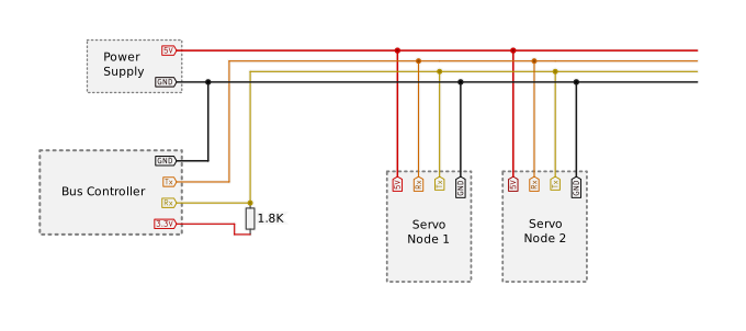
PLEASE NOTE! The bus controller needs to have a low latency to get fast communication with the servos. Most standard USB to Serial converters buffer the data and only transfers every 10 ms or so. This becomes a problem since the communication protocol will wait for the response from each servo before moving on to the next, adding huge delays.
To get the best communication speed it is recommended to use an "Adafruit ItsyBitsy M0 Express" (or similar ARM based Arduino) as the USB to Serial converter. Just program the Arduino with the usbToSerial.h configuration in the ArduinoSketch to get started. In usbToSerial.h you can also configure any regular servos you want to control together with the ServoProject modified ones.
Using the PWM interface is not recommended due to low resolution and high noise, but it is possible by modifying the configuration file. To enable PWM control replace the getCommunicationHandler() function with the version below.
    static std::unique_ptr<Communication> getCommunicationHandler()
    {
        Serial.begin(115200);
        auto com = std::make_unique<Communication>(SerialComOptimizer(&Serial));
        uint8_t pwmPin = 0; // Rx pin, ONLY CONNECT TO 3.3V LOGIC!!!!
        uint8_t controlSpeed = 14;
        uint8_t backlashControlSpeed = 2;
        float scale = 2.0f; // 2 units per us (4096 units == 360 deg)
        float offset = 1024.0f; // move to 1024 units (90 deg) for 1500 us pwm signal
        com->addCommunicationNode(
                std::make_unique<DCServoCommunicationHandlerWithPwmInterface>(1,
                    createDCServo<SetupConfigHolder>(controlSpeed, backlashControlSpeed),
                    pwmPin, scale, offset));
        return com;
}Open Source License
ServoProject is free software. You can redistribute it and/or modify it under the terms of Creative Commons Attribution 3.0 United States License.
To view a copy of this license, visit http://creativecommons.org/licenses/by/3.0/us/
| Qty | Value | Footprint | References |
|---|---|---|---|
| 2 | 120 | Resistor_THT:R_Axial_DIN0207_L6.3mm_D2.5mm_P7.62mm_Horizontal | R1, R3 |
| 2 | 8.2K | Resistor_THT:R_Axial_DIN0207_L6.3mm_D2.5mm_P7.62mm_Horizontal | R2, R4 |
| 2 | ITR8307 | OptoDevice:Everlight_ITR8307 | U1, U2 |
It measures 9 × 3.6 mm and has 2 copper layers, 1.6 mm thick.
6 parts, built around the ITR8307. The full list of its parts is on this page, with links to each part's symbol and footprint where PCBKit's library has them.
From the adamb314/ServoProject repository on GitHub, at the commit this page was made from: the board is PcbDesignes/legacy/ServoCoreless/OpticalEncoder/OpticalEncoder.kicad_pcb and its schematic PcbDesignes/combined/combined.kicad_sch. PCBKit opens the board in the browser, with nothing to install.
Its repository states no licence, so its author keeps all rights: ask adamb314 before reusing the design.


erufes/Seguidor2021-H
Projeto de hardware do robô da equipe de Seguidor de Linha do projeto Equipe de Robótica da UFES (ERUS) para o robô de 2020 e 2021, com objetivo de construir um robô para competir pelas primeiras posições na IronCup…

RoboticsBrno/RB0001-LineSensor
Line sensor with 8 sensors for measuring the reflectance of the surface with integrated I2C A/D converter.


BartekOrchowski/MiniSumoAVR
This project is a MiniSumo robot developed during a workshop organized by the KoNaR student scientific association.


ToonVanEyck/OpenFlap
The OpenFlap project aims to create a open source, affordable split-flap display for the makers and tinkerers of the world.
