2 layers110 × 125 mm
Chaincom test
ToonVanEyck/OpenFlap
The OpenFlap project aims to create a open source, affordable split-flap display for the makers and tinkerers of the world.
182 parts98

 ToonVanEyck/OpenFlap98
The OpenFlap project aims to create a open source, affordable split-flap display for the makers and tinkerers of the world.
Side panel is an open-source printed circuit board by ToonVanEyck, from the ToonVanEyck/OpenFlap repository on GitHub. It is a 2-layer board of 96 × 120.1 mm with 43 parts on 32 nets, routed with 334 tracks and 97 vias.
It is built around the L9110S, ITR8307 and NUP4202W1, with the XC6206P332MR, AP2302B and PESD5V0L among its other parts. Its parts include 9 resistors, 7 ICs, 5 capacitors, 4 connectors and 3 diodes. It belongs with the lEDs and displays boards of this library.


!!! warning
🚨 This is still a work in progress. Using the the code and files in this repository to create your own display is not recommended at the moment! 🚨The OpenFlap project aims to create a open source, affordable split-flap display for the makers and tinkerers of the world. This repository houses all the required files to build, program and modify your very own split-flap display.
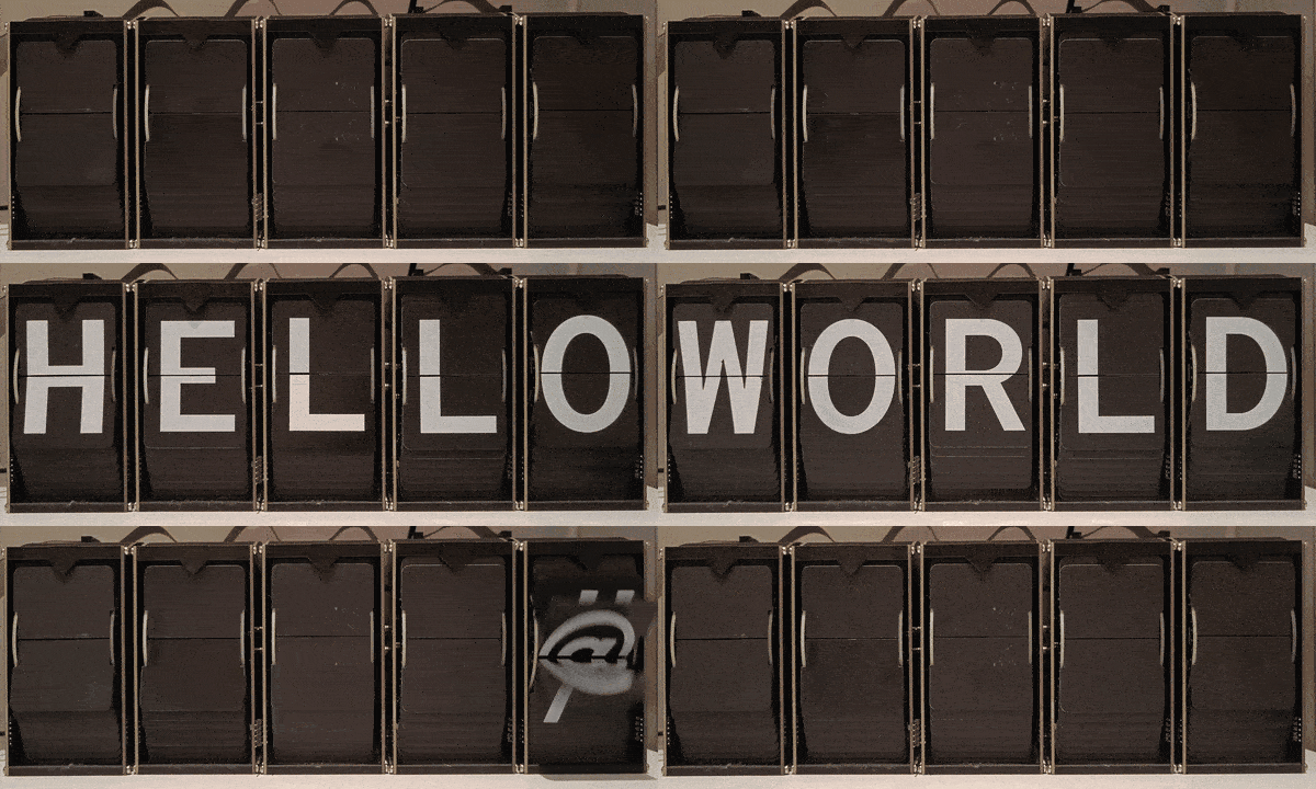
The OpenFlap system is designed to be modular and expandable, using common components and manufacturing techniques such as 3D printing and printed circuit boards.
The OpenFlap system uses DC geared motors instead of traditional stepper motors. This simplifies the mechanical design and reduces the cost of the system. Additionally this reduces the power consumption of the system and allows the split-flap display to rotate faster than the traditionally used stepper motors.
The OpenFlap system is designed to be as plug and play as possible. The system is able to determine it's own display size, and should only require calibration once.
The OpenFlap system has a web interface that allows local control of the display. The web interface uses a HTTP API to communicate with the display, this API also allows external services to communicate with the display. No authentication or security measures are implemented at the moment.
The OpenFlap system can connect to your local WiFi network or host it's own network.
... know more about how the OpenFlap system works.
| Qty | Value | Footprint | References |
|---|---|---|---|
| 10 | MountingHole | MountingHole:MountingHole_2.7mm | H1, H2, H3, H4, H5, H6, H7, H8, H9, H10 |
| 5 | 20K | Resistor_SMD:R_0805_2012Metric | R1, R2, R3, R6, R8 |
| 3 | 1uF | Capacitor_SMD:C_0805_2012Metric | C3, C4, C5 |
| 3 | ITR8307 | OptoDevice:OnSemi_CASE100CY | U3, U4, U5 |
| 2 | 100nF | Capacitor_SMD:C_0805_2012Metric | C1, C2 |
| 2 | OSHW-Logo_7.5x8mm_SilkScreen | Symbol:OSHW-Logo_7.5x8mm_SilkScreen | OSHW-LOGO-1, OSHW-LOGO-2 |
| 1 | 100R | Resistor_SMD:R_0805_2012Metric | R5 |
| 1 | 12p redfit skedd | Skedd Connector:490107671212 | J4 |
| 1 | 16R | Resistor_SMD:R_0805_2012Metric | R4 |
| 1 | 220R | Resistor_SMD:R_0805_2012Metric | R9 |
| 1 | 75K | Resistor_SMD:R_0805_2012Metric | R7 |
| 1 | 8p redfit skedd | Skedd Connector:490107670812 | J3 |
| 1 | AP2302B | Package_TO_SOT_SMD:SOT-23 | Q1 |
| 1 | Bottom Connector | Connector_PinSocket_2.54mm:PinSocket_2x07_P2.54mm_Horizontal | J2 |
| 1 | GA12-N20 12V 60rpm | GA12-N20:GA12-N20 Motor Vertical | M1 |
| 1 | L9110S | Package_SO:SOP-8_3.76x4.96mm_P1.27mm | U2 |
| 1 | NUP4202 | Package_TO_SOT_SMD:SOT-23-6 | U7 |
| 1 | PESD12V | Package_TO_SOT_SMD:SOT-23-3 | D2 |
| 1 | PESD5V | Package_TO_SOT_SMD:SOT-23-3 | D1 |
| 1 | PY32F003F1xPx | Package_SO:TSSOP-20_4.4x6.5mm_P0.65mm | U1 |
| 1 | TestPoint | TestPoint:TestPoint_Pad_D1.5mm | TP1 |
| 1 | Top Connector | Connector_PinHeader_2.54mm:PinHeader_2x07_P2.54mm_Horizontal | J1 |
| 1 | XC6206P332MR | Package_TO_SOT_SMD:SOT-23-3 | U9 |
| 1 | XL-1606SURC | LED_SMD:LED_Kingbright_APA1606_1.6x0.6mm_Horizontal | D3 |
ToonVanEyck/OpenFlap
The OpenFlap project aims to create a open source, affordable split-flap display for the makers and tinkerers of the world.

ToonVanEyck/OpenFlap
The OpenFlap project aims to create a open source, affordable split-flap display for the makers and tinkerers of the world.

ToonVanEyck/OpenFlap
The OpenFlap project aims to create a open source, affordable split-flap display for the makers and tinkerers of the world.

PowerPlane/insert-coin
The "Insert Coin" cards are PCB-as-business-card builds where the coin cell is the user interaction: slide it into the holder and the card boots, blinks, listens, taps NFC, then sleeps.

MeesCode/gameboy-pcb
custom gameboy-esque pcb running an stm32 and my own tiny game engine


AndreaGiulianini/lira
57-key 40% + numpad keyboard: Bluetooth/USB-C, hot-swap MX, RMK/Vial, and a built-in USB sound card (3.5 mm headset jack). Generated from source with KiCad.


bryan-bpms/Reservoir_Circuit
ECE 298 Reservoir Circuit Schematic and PCB Design, modeled in KiCad
It measures 96 × 120.1 mm and has 2 copper layers, 1.6 mm thick.
43 parts, built around the L9110S, ITR8307, NUP4202W1 and XC6206P332MR. The full list of its parts is on this page, with links to each part's symbol and footprint where PCBKit's library has them.
From the ToonVanEyck/OpenFlap repository on GitHub, at the commit this page was made from: the board is hardware/module/side_panel/src/side_panel.kicad_pcb and its schematic hardware/controller/src/controller.kicad_sch. PCBKit opens the board in the browser, with nothing to install.
Its repository states no licence, so its author keeps all rights: ask ToonVanEyck before reusing the design.