
2 layers247.7 × 127 mm
Euclid36
sadekbaroudi/euclid36
At the time of creation, using Kicad 5.1.9 - This may not work with future versions
130 parts24

 Zokhoi/mf3dre2
Reverse engineered schematics and PCB design of DJTechTools Midi Fighter 3D
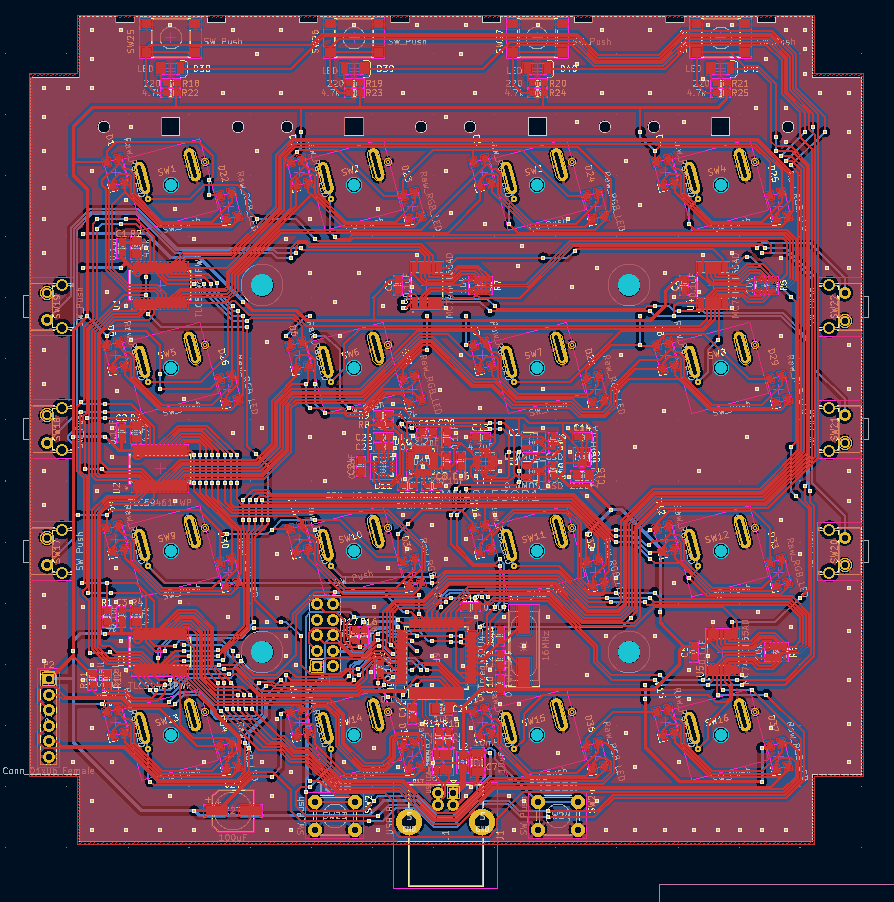
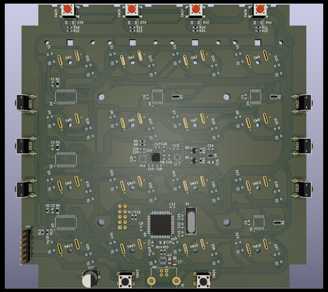
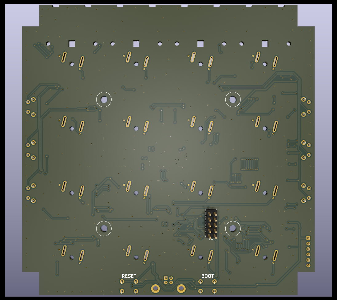
Re mf3d is an open-source printed circuit board by Zokhoi, from the Zokhoi/mf3dre repository on GitHub. It is a 2-layer board of 136 × 135 mm with 143 parts on 164 nets, routed with 3,024 tracks and 531 vias.
It is built around the ATMEGA32U4-AU, TLC59461PWP and MC74HC165AD, with the MMA8453QR1, ZXCL330H5TA and USBLC6-2SC6 among its other parts. Its parts include 37 diodes, 28 switches, 27 capacitors, 25 resistors and 11 ICs. It belongs with the AVR (ATmega, ATtiny) boards of this library.


This repo holds the reverse engineered schematics and PCB design that should hopefully be functionally identical to the DJTechTools Midi Fighter 3D. This was done in the effort of creating functional firmware for the MF3D, as DJTechTools has shared or open sourced every Midi Fighter firmware except for MF3D.
The repository requires KiCAD v7.
However, there are also some components that I am not very certain about, which I hope would be uncovered as time goes by. In specific, the list of items are:
Here are some of the other details that I have noticed while performing the reverse engineering.
In an email exchange with DJTT, they have stated that the magnometer IST8308 has been replaced by accelerometer MMA8453Q, but both of these chips are present on my board. In addition, the circuitry around IST8308 (U11) does not seem to correspond to the application circuit given in its datasheet.
| Qty | Value | Footprint | References |
|---|---|---|---|
| 32 | Raw_RGB_LED | assets:Raw_RGB_LED_Tilted | D1, D2, D10, D11, D12, D13, D14, D15, D16, D22, D23, D24, D25, D26, D27, D28 +16 |
| 16 | 0.1uF | Capacitor_SMD:C_0603_1608Metric_Pad1.08x0.95mm_HandSolder | C1, C2, C3, C4, C5, C6, C8, C9, C10, C11, C12, C16, C18, C20, C24, C25 |
| 16 | SW_Push | assets:SW-68-Tilted | SW1, SW2, SW3, SW4, SW5, SW6, SW7, SW8, SW9, SW10, SW11, SW12, SW13, SW14, SW15, SW16 |
| 9 | 4.7k | Resistor_SMD:R_0603_1608Metric_Pad0.98x0.95mm_HandSolder | R1, R8, R9, R16, R17, R22, R23, R24, R25 |
| 6 | SW_Push | Button_Switch_THT:SW_Tactile_SPST_Angled_PTS645Vx39-2LFS | SW17, SW18, SW19, SW20, SW21, SW22 |
| 4 | 220 | Resistor_SMD:R_0603_1608Metric_Pad0.98x0.95mm_HandSolder | R18, R19, R20, R21 |
| 4 | LED | assets:White_LED | D38, D39, D40, D41 |
| 4 | SW_Push | Button_Switch_SMD:SW_SPST_PTS645 | SW25, SW26, SW27, SW28 |
| 3 | 10k | Resistor_SMD:R_Array_Convex_5x0603 | R5, R6, R7 |
| 3 | 4.7k | Resistor_SMD:R_0805_2012Metric_Pad1.20x1.40mm_HandSolder | R2, R3, R4 |
| 3 | MC74HC165AD | assets:SOP65P640X120-16N | U4, U5, U6 |
| 3 | TLC59461PWP | assets:TLC59461PWP | U1, U2, U3 |
| 2 | 10k | Resistor_SMD:R_0603_1608Metric_Pad0.98x0.95mm_HandSolder | R10, R13 |
| 2 | 22 | Resistor_SMD:R_0603_1608Metric_Pad0.98x0.95mm_HandSolder | R14, R15 |
| 2 | 22pF | Capacitor_SMD:C_0603_1608Metric_Pad1.08x0.95mm_HandSolder | C22, C23 |
| 2 | 4.7uF | Capacitor_SMD:C_0603_1608Metric_Pad1.08x0.95mm_HandSolder | C13, C26 |
| 2 | Q_NMOS_GSD | Package_TO_SOT_SMD:SOT-23 | Q1, Q2 |
| 2 | R_Small | Resistor_SMD:R_0603_1608Metric_Pad0.98x0.95mm_HandSolder | R11, R12 |
| 2 | SW_Push | Button_Switch_THT:SW_PUSH_6mm | SW23, SW24 |
| 1 | 100uF | Capacitor_SMD:CP_Elec_6.3x5.2 | C27 |
| 1 | 10mH | Inductor_SMD:L_0805_2012Metric_Pad1.15x1.40mm_HandSolder | L2 |
| 1 | 10nF | Capacitor_SMD:C_0603_1608Metric_Pad1.08x0.95mm_HandSolder | C19 |
| 1 | 10uF | Capacitor_SMD:C_1206_3216Metric_Pad1.33x1.80mm_HandSolder | C7 |
| 1 | 16MHz | Crystal:Crystal_SMD_HC49-SD | X1 |
| 1 | 1uF | Capacitor_SMD:C_0603_1608Metric_Pad1.08x0.95mm_HandSolder | C14 |
| 1 | 1uF | Capacitor_SMD:C_0805_2012Metric_Pad1.18x1.45mm_HandSolder | C21 |
| 1 | 2.2nF | Capacitor_SMD:C_0603_1608Metric_Pad1.08x0.95mm_HandSolder | C17 |
| 1 | 2.2uF | Capacitor_SMD:C_0805_2012Metric_Pad1.18x1.45mm_HandSolder | C15 |
| 1 | ATmega32U4-A | Package_QFP:TQFP-44_10x10mm_P0.8mm | U9 |
| 1 | Conn_01x06_Female | Connector_PinHeader_2.54mm:PinHeader_1x06_P2.54mm_Vertical | P2 |
| 1 | Conn_02x05_Odd_Even | Connector_PinHeader_2.54mm:PinHeader_2x05_P2.54mm_Vertical | P1 |
| 1 | ITG-3200 | assets:QFN-24_4x4mm_P0.5mm | U10 |
| 1 | MMA8453QR1 | assets:QFN50P300X300X100-16N | U7 |
| 1 | QFN-16_3x3mm_P0.5mm | assets:QFN-16_3x3mm_P0.5mm | U11 |
| 1 | USBLC6-2SC6 | assets:SOT95P280X145-6N | D17 |
| 1 | USB_B | Connector_USB:USB_B_Lumberg_2411_02_Horizontal | J1 |
| 1 | ZXCL330H5TA | Package_TO_SOT_SMD:SOT-353_SC-70-5 | U8 |
The 135 most common of 143 parts.
sadekbaroudi/euclid36
At the time of creation, using Kicad 5.1.9 - This may not work with future versions

eightbitraptor/65_keyboard_untitled
My as yet unnamed 65% keyboard design


sini6a/phnx
PHNX is an ergonomic keyboard featuring 54 MX compatible switches. It is inspired by the Miryoku layout and includes one additional row at the top along with macro keys on both sides.

palexander23/HurdyGurdy-PCB
This repository contains PCB design files, that will go towards the eventual creation of an electronic Hurdy Gurdy.


jackhumbert/reform
This is the main repository for the MNT Reform open source laptop.
It measures 136 × 135 mm and has 2 copper layers, 1.6 mm thick.
143 parts, built around the ATMEGA32U4-AU, TLC59461PWP, MC74HC165AD and MMA8453QR1. The full list of its parts is on this page, with links to each part's symbol and footprint where PCBKit's library has them.
From the Zokhoi/mf3dre repository on GitHub, at the commit this page was made from: the board is PCB/re-mf3d.kicad_pcb and its schematic PCB/btn.kicad_sch. PCBKit opens the board in the browser, with nothing to install.
Its repository states no licence, so its author keeps all rights: ask Zokhoi before reusing the design.