4 layers60 × 66.5 mm

 VladimirBioACS/lora-sensor-tag-pcb-project1
Simple LoRa humidity and temperature monitoring device, based on the ESP32-Wroom-D SoC module. Repo contains KiCAD 10 project for LoRa Sensor TAG device with external component libs.
Lora sensor tag is an open-source printed circuit board by VladimirBioACS, from the VladimirBioACS/lora-sensor-tag-pcb-project repository on GitHub. It is a 4-layer board of 55.4 × 63.3 mm with 147 parts on 126 nets, routed with 268 tracks and 134 vias.
It is built around the ESP32-WROOM-32D, PE4259-63 and SX1276IMLTRT, with the SHT20 and TPS63070RNMR among its other parts. Its parts include 46 resistors, 43 capacitors, 10 diodes, 8 ICs and 7 inductors. It belongs with the radio and wireless and sensors and measurement boards and the ESP32 boards of this library.


Simple LoRa humidity and temperature monitoring device, based on the ESP32-Wroom-D SoC module. Repo contains KiCAD 10 project for LoRa Sensor TAG device with external component libs.
The architecture of the project is described with the diagram below (lora_sensor_tag_architecture.jpg):
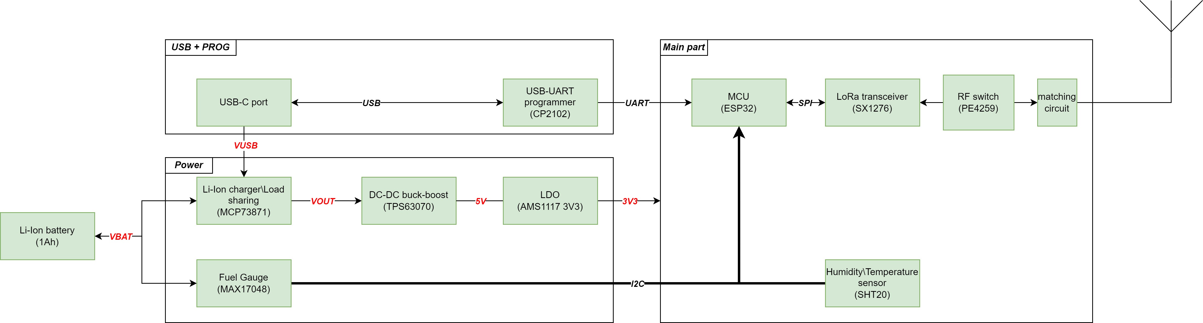
The LoRa Sensor Project is designed to create a network of low-power, long-range sensors for environmental monitoring. The project aims to leverage LoRa technology to enable efficient data collection from remote locations, providing real-time insights into various environmental parameters such as temperature and humidity. The LoRa modem works within 433 Mhz LF baseband.
It is developed simply for the educational purpose, aiming to provide students and hobbyists with hands-on experience in building and managing a LoRa-based sensor network.
The device composed of several key components:
The following key components were used:
| Qty | Value | Footprint | References |
|---|---|---|---|
| 17 | TestPoint | TestPoint:TestPoint_Pad_D1.0mm | TP1, TP2, TP3, TP4, TP5, TP6, TP7, TP8, TP10, TP11, TP12, TP14, TP15, TP16, TP17, TP18 +1 |
| 12 | 100nF | Capacitor_SMD:C_0603_1608Metric | C1, C2, C3, C4, C5, C6, C7, C28, C29, C30, C43, C44 |
| 9 | 470R | Resistor_SMD:R_0603_1608Metric | R5, R6, R7, R23, R27, R30, R31, R42, R45 |
| 7 | 0R | Resistor_SMD:R_0603_1608Metric | R2, R13, R14, R15, R16, R17, R18 |
| 7 | 10K | Resistor_SMD:R_0603_1608Metric | R8, R11, R21, R25, R26, R28, R43 |
| 4 | 47pF | Capacitor_SMD:C_0402_1005Metric | C9, C21, C22, C25 |
| 4 | MountingHole | MountingHole:MountingHole_2.1mm | H1, H2, H3, H4 |
| 4 | R | Resistor_SMD:R_0603_1608Metric | R19, R20, R41, R44 |
| 3 | 10uF | Capacitor_SMD:C_0603_1608Metric | C31, C35, C41 |
| 3 | 1N630xCA | Diode_SMD:D_0603_1608Metric | D6, D7, D8 |
| 3 | 22uF | Capacitor_SMD:C_0805_2012Metric | C36, C37, C38 |
| 3 | 5K | Resistor_SMD:R_0603_1608Metric | R1, R32, R35 |
| 3 | NC | Capacitor_SMD:C_0402_1005Metric | C11, C16, C17 |
| 3 | NPN | Package_TO_SOT_SMD:SOT-23 | Q1, Q2, Q3 |
| 2 | 10pF | Capacitor_SMD:C_0603_1608Metric | C18, C19 |
| 2 | 10uF | Capacitor_SMD:C_0805_2012Metric | C33, C34 |
| 2 | 1nF | Capacitor_SMD:C_0603_1608Metric | C23, C24 |
| 2 | 4.7pF | Capacitor_SMD:C_0402_1005Metric | C8, C14 |
| 2 | 4.7uF | Capacitor_SMD:C_0603_1608Metric | C32, C39 |
| 2 | 47K | Resistor_SMD:R_0603_1608Metric | R22, R38 |
| 2 | 4K7 | Resistor_SMD:R_0603_1608Metric | R3, R4 |
| 2 | 5K1 | Resistor_SMD:R_0603_1608Metric | R33, R34 |
| 2 | Conn_Coaxial | Connector_Coaxial:SMA_BAT_Wireless_BWSMA-KWE-Z001 | J1, J2 |
| 1 | 0R | Resistor_SMD:R_0402_1005Metric | R46 |
| 1 | 1.5uH | Inductor_SMD:L_Coilcraft_XxL4040 | L7 |
| 1 | 100K | Resistor_SMD:R_0603_1608Metric | R9 |
| 1 | 100nF | Capacitor_SMD:C_0402_1005Metric | C40 |
| 1 | 10nF | Capacitor_SMD:C_0402_1005Metric | C20 |
| 1 | 110K | Resistor_SMD:R_0603_1608Metric | R29 |
| 1 | 12nH | Inductor_SMD:L_0402_1005Metric | L3 |
| 1 | 150K | Resistor_SMD:R_0603_1608Metric | R12 |
| 1 | 18nH | Inductor_SMD:L_0402_1005Metric | L1 |
| 1 | 1K3 | Resistor_SMD:R_0603_1608Metric | R37 |
| 1 | 2.2pF | Capacitor_SMD:C_0402_1005Metric | C12 |
| 1 | 220nH | Inductor_SMD:L_0402_1005Metric | L6 |
| 1 | 22K | Resistor_SMD:R_0603_1608Metric | R36 |
| 1 | 2K5 | Resistor_SMD:R_0603_1608Metric | R39 |
| 1 | 32 MHz | Crystal:Crystal_SMD_3225-4Pin_3.2x2.5mm | Y1 |
| 1 | 330K | Resistor_SMD:R_0603_1608Metric | R24 |
| 1 | 47 pF | Capacitor_SMD:C_0402_1005Metric | C10 |
| 1 | 470K | Resistor_SMD:R_0603_1608Metric | R10 |
| 1 | 5.1pF | Capacitor_SMD:C_0402_1005Metric | C26 |
| 1 | 5.6pF | Capacitor_SMD:C_0402_1005Metric | C27 |
| 1 | 6.8pF | Capacitor_SMD:C_0402_1005Metric | C15 |
| 1 | C | Capacitor_SMD:C_0402_1005Metric | C13 |
| 1 | CP2102N-Axx-xQFN28 | Package_DFN_QFN:QFN-28-1EP_5x5mm_P0.5mm_EP3.35x3.35mm | U9 |
| 1 | ESP32-WROOM-32D | RF_Module:ESP32-WROOM-32D | U2 |
| 1 | L | Inductor_SMD:L_0402_1005Metric | L5 |
| 1 | L | Resistor_SMD:R_0402_1005Metric | L2 |
| 1 | L | Capacitor_SMD:C_0402_1005Metric | L4 |
| 1 | LED_PWR | LED_SMD:LED_0603_1608Metric | D5 |
| 1 | LED_RX | LED_SMD:LED_0603_1608Metric | D9 |
| 1 | LED_TX | LED_SMD:LED_0603_1608Metric | D10 |
| 1 | LOGO | wifi_sign:wifi_sign_footprint | G*** |
| 1 | Li-ion_bat_conn | Connector_PinHeader_2.54mm:PinHeader_1x02_P2.54mm_Vertical | J3 |
| 1 | MAX17048G_T10 | MAX17048G_T10:SON50P200X200X80-9N | U8 |
| 1 | MCP73871-2CAI_ML | MCP73871-2CAI_ML:QFN50P400X400X100-21N | U6 |
| 1 | MCU_ST | LED_SMD:LED_0603_1608Metric | D1 |
| 1 | NC | Resistor_SMD:R_0603_1608Metric | R40 |
| 1 | PE4259 | PE4259:SOT65P215X110-6N | U3 |
| 1 | PG | LED_SMD:LED_0603_1608Metric | D2 |
| 1 | SHT20 | SHT20:XDCR_SHT20 | U4 |
| 1 | STAT1\LBO | LED_SMD:LED_0603_1608Metric | D4 |
| 1 | STAT2 | LED_SMD:LED_0603_1608Metric | D3 |
| 1 | SW_MCU_PROG | Button_Switch_SMD:SW_Push_1TS009xxxx-xxxx-xxxx_6x6x5mm | SW2 |
| 1 | SW_MCU_RST | Button_Switch_SMD:SW_Push_1TS009xxxx-xxxx-xxxx_6x6x5mm | SW1 |
| 1 | SW_Nidec_CAS-120A1 | Button_Switch_SMD:Nidec_Copal_CAS-120A | SW_PWR1 |
| 1 | SX1276IMLTRT | SX1276IMLTRT:QFN65P600X600X100-29N | U1 |
| 1 | TPS63070RNMR | TPS63070RNMR:VREG_TPS63070RNMR | U5 |
| 1 | USB_C_Receptacle_USB2.0_14P | Connector_USB:USB_C_Receptacle_XKB_U262-16XN-4BVC11 | J4 |

proveskit/development_boards
Miscellaneous dev boards to test the components of the PROVES Kit on a smaller scale.


Chromico/sht20-breakout-board
A simple breakout board based on the SHT20 sensor


softerhardware/Hermes-Lite2
A second generation low-cost amateur HF software defined radio transceiver.
It measures 55.4 × 63.3 mm and has 4 copper layers, 1.6 mm thick.
147 parts, built around the ESP32-WROOM-32D, PE4259-63, SX1276IMLTRT and SHT20. The full list of its parts is on this page, with links to each part's symbol and footprint where PCBKit's library has them.
From the VladimirBioACS/lora-sensor-tag-pcb-project repository on GitHub, at the commit this page was made from: the board is lora_sensor_tag/lora_sensor_tag.kicad_pcb and its schematic lora_sensor_tag/lora_sensor_tag.kicad_sch. PCBKit opens the board in the browser, with nothing to install.
Its repository states no licence, so its author keeps all rights: ask VladimirBioACS before reusing the design.