2 layers100 × 100 mm

 VIP-LES/leos-F26-radio-pcb
radio pcb updated fall 2026
LEOS F26-radio is an open-source printed circuit board by VIP-LES, from the VIP-LES/leos-F26-radio-pcb repository on GitHub. It is a 2-layer board of 100 × 100 mm with 29 parts on 62 nets, routed with 180 tracks and 81 vias.
It is built around the E22-900M30S, MCP2562FD-E/P and MCP2518FDT-E/SL-HX, with the CL21B104KBCNNNC, CL21C100CBANNNC and CL31B226MPHNNNE among its other parts. Its parts include 13 capacitors, 3 ICs, 2 resistors, 2 connectors and 1 crystal. It belongs with the radio and wireless boards and the RP2040 boards of this library.


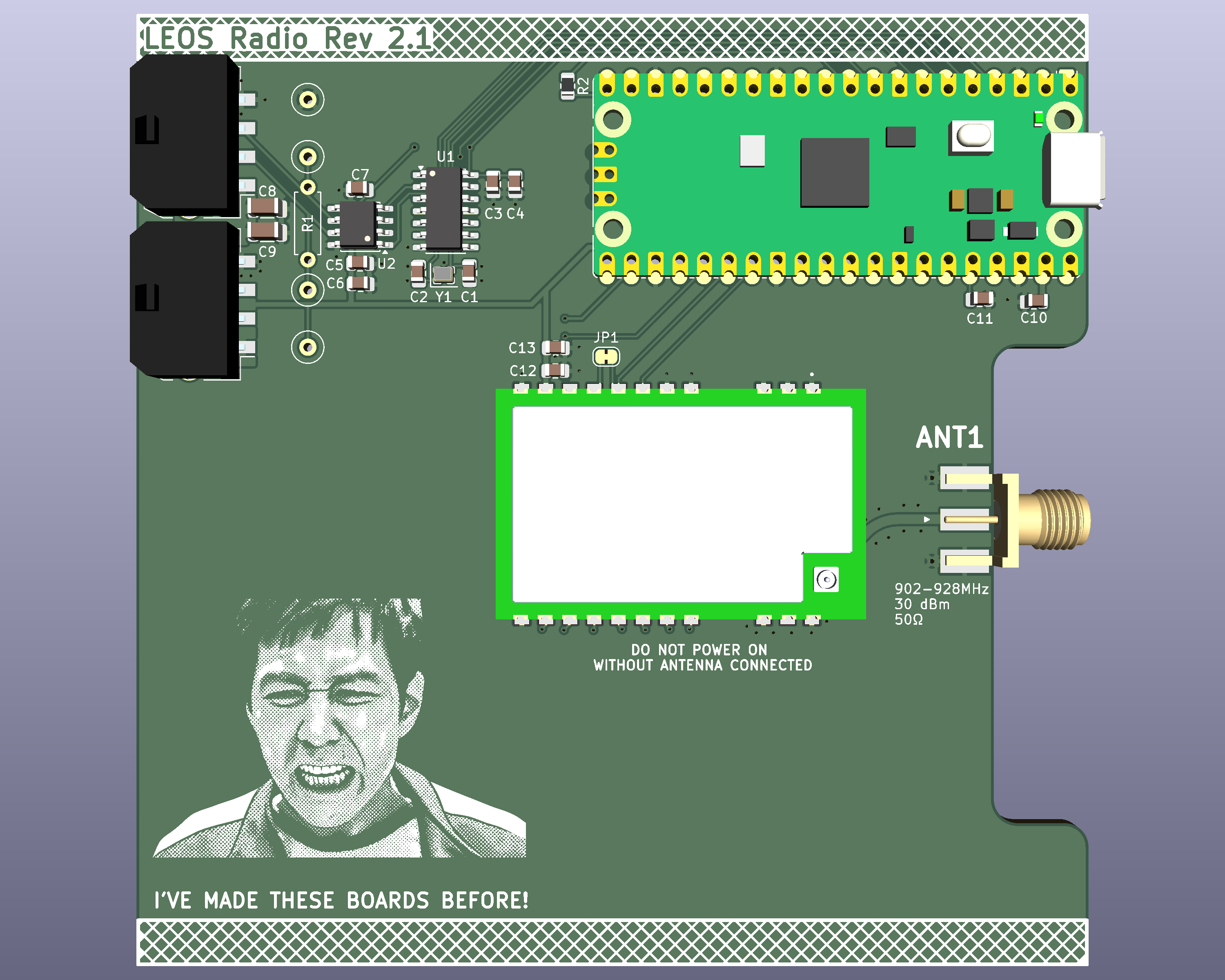
This repository contains the KiCad schematic and PCB layout for the LEOS Radio PCB made fall 2026. The board integrates a Raspberry Pi Pico, an E22-900M30S LoRa radio module, and a CAN-FD interface.
The Raspberry Pi Pico communicates with the radio module through SPI1 and the MCP2518FD CAN-FD controller through SPI0. An MCP2562FD transceiver connects the CAN controller to the LEOS CAN bus. An SMA connector provides the connection for an external antenna.
Main hardware functions:
| Qty | Value | Footprint | References |
|---|---|---|---|
| 5 | 0.1u | Capacitor_SMD:C_0805_2012Metric | C3, C5, C7, C10, C12 |
| 3 | 1u | Capacitor_SMD:C_0805_2012Metric | C4, C6, C13 |
| 2 | 10p | Capacitor_SMD:C_0805_2012Metric | C1, C2 |
| 2 | 22u | Capacitor_SMD:C_1206_3216Metric | C8, C9 |
| 2 | MicroFit_1x4 | LEOS:Molex_MicroFit3.0_43650-0410_1x04_Horizontal | J1, J2 |
| 1 | 10k | Resistor_SMD:R_0805_2012Metric | R2 |
| 1 | 10u | Capacitor_SMD:C_0805_2012Metric | C11 |
| 1 | 120 | Resistor_THT:R_Axial_DIN0207_L6.3mm_D2.5mm_P7.62mm_Horizontal | R1 |
| 1 | 40 MHz | Crystal:Crystal_SMD_2016-4Pin_2.0x1.6mm | Y1 |
| 1 | 5V Test Point | TestPoint:TestPoint_Loop_D2.60mm_Drill0.9mm_Beaded | TP3 |
| 1 | 900MHz SMA | Connector_Coaxial:SMA_Molex_73251-1153_EdgeMount_Horizontal | ANT1 |
| 1 | CAN-H Test Point | TestPoint:TestPoint_Loop_D2.60mm_Drill0.9mm_Beaded | TP1 |
| 1 | CAN-L Test Point | TestPoint:TestPoint_Loop_D2.60mm_Drill0.9mm_Beaded | TP2 |
| 1 | E22-900M30S | LEOS:XCVR_E22-900M30S | U3 |
| 1 | GND Test Point | TestPoint:TestPoint_Loop_D2.60mm_Drill0.9mm_Beaded | TP4 |
| 1 | LOGO | LOGO | G*** |
| 1 | MCP2518FD | Package_SO:SOIC-14_3.9x8.7mm_P1.27mm | U1 |
| 1 | MCP2562FD | Package_SO:SOIC-8_3.9x4.9mm_P1.27mm | U2 |
| 1 | RaspberryPi Pico | Module:RaspberryPi_Pico_Common_Unspecified | A1 |
| 1 | SolderJumper_2_Bridged | Jumper:SolderJumper-2_P1.3mm_Bridged_RoundedPad1.0x1.5mm | JP1 |

VIP-LES/leos-efm-pcb
This repository is the starting-point PCB template for VIP Lightning From the Edge of Space (LEOS). All LEOS modules should be spun off from this template so that every module begins with the standard Raspberry Pi Pico…


VIP-LES/flight-computer-pcb
The flight computer PCB stack design. Started Fall '25

It measures 100 × 100 mm and has 2 copper layers, 1.6 mm thick.
29 parts, built around the E22-900M30S, MCP2562FD-E/P, MCP2518FDT-E/SL-HX and CL21B104KBCNNNC. The full list of its parts is on this page, with links to each part's symbol and footprint where PCBKit's library has them.
From the VIP-LES/leos-F26-radio-pcb repository on GitHub, at the commit this page was made from: the board is LEOS-F26-radio.kicad_pcb and its schematic LEOS-F26-radio.kicad_sch. PCBKit opens the board in the browser, with nothing to install.
Its repository states no licence, so its author keeps all rights: ask VIP-LES before reusing the design.