2 layers100 × 100 mm
LEOS dualpower
MatthewIsHere/leos-dualpower-pcb
A backup 5V stackable power supply for the LEOS High Altitude Balloon Stack
39 parts

 VIP-LES/leos-F26-power-pcb
power board made in fall 2026
LEOS F26-power is an open-source printed circuit board by VIP-LES, from the VIP-LES/leos-F26-power-pcb repository on GitHub. It is a 4-layer board of 100 × 100 mm with 64 parts on 95 nets, routed with 207 tracks and 127 vias.
It is built around the MCP2562FD-E/P, TPS54540BDDA and MCP2518FDT-E/SL-HX, with the CL21B104KBCNNNC, CL21A475KBQNNNE and S2B-XH-A among its other parts. Its parts include 15 capacitors, 9 connectors, 6 ICs, 2 diodes and 2 inductors. It belongs with the RP2040 boards of this library.


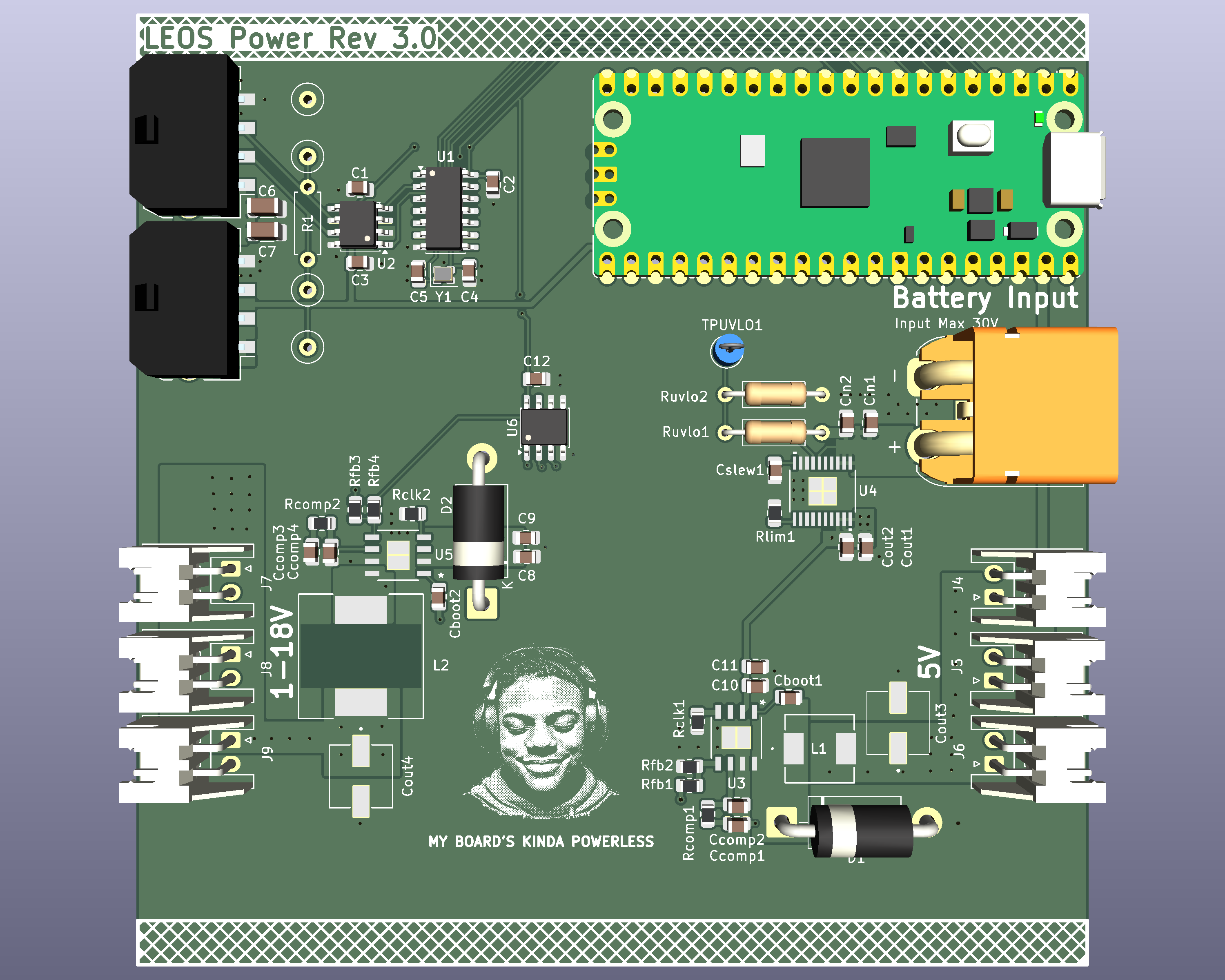
This repository contains the KiCad design files for the LEOS power board made fall 2026. The board is designed to accept power from a 6S LiPo battery, provide input protection, and generate adjustable DC output for other LEOS components. This board also includes the base elements from the template board.
The design uses a Texas Instruments TPS16630 eFuse for input protection and two TPS54540B buck converters for voltage regulation. A Raspberry Pi Pico controls the output voltage through the MCP41100 SPI digital potentiometer in one of the buck converter's feedback network.
The target output ranges are 5V at up to 5A and 1-18V at up to 5A.
The power board has three main functions: Input protection: A TPS16630 eFuse provides adjustable undervoltage lockout, overvoltage protection, current limiting, and controlled startup. DC-DC conversion: Two TPS54540B switching buck converters step down the battery voltage to both a fixed and adjustable output voltage. Digital control: A Raspberry Pi Pico communicates with an MCP41100 digital potentiometer over SPI to adjust one of the buck converters' feedback resistance.
Input source: 6S LiPo battery Nominal input voltage: 22.2V Fully charged battery voltage: 25.2V Input undervoltage cutoff: Approximately 19-19.5V Output voltage: 5V and approximately 1-18V adjustable Maximum output current: 5A Buck converter: TPS54540B eFuse: TPS16630 Digital potentiometer: MCP41100T-I/SN Control interface: SPI from Raspberry Pi Pico
| Qty | Value | Footprint | References |
|---|---|---|---|
| 7 | 0.1u | Capacitor_SMD:C_0805_2012Metric | C1, C2, C3, C12, Cboot1, Cboot2, Cin2 |
| 4 | 4.7uF | Capacitor_SMD:C_0805_2012Metric | C8, C9, C10, C11 |
| 3 | 1-18V | Connector_JST:JST_XH_S2B-XH-A_1x02_P2.50mm_Horizontal | J7, J8, J9 |
| 3 | 10uF | Capacitor_SMD:C_0805_2012Metric | Cin1, Cout1, Cout2 |
| 3 | 5V | Connector_JST:JST_XH_S2B-XH-A_1x02_P2.50mm_Horizontal | J4, J5, J6 |
| 2 | 10p | Capacitor_SMD:C_0805_2012Metric | C4, C5 |
| 2 | 22u | Capacitor_SMD:C_1206_3216Metric | C6, C7 |
| 2 | 4.7n | Capacitor_SMD:C_0805_2012Metric | Ccomp1, Cslew1 |
| 2 | 47u | LEOS:CAPAE660X600N | Cout3, Cout4 |
| 2 | 6.8p | Capacitor_SMD:C_0805_2012Metric | Ccomp2, Ccomp4 |
| 2 | 60V 20A | Diode_THT:D_DO-201AD_P15.24mm_Horizontal | D1, D2 |
| 2 | MicroFit_1x4 | LEOS:Molex_MicroFit3.0_43650-0410_1x04_Horizontal | J1, J2 |
| 2 | TPS54540BDDA | LEOS:SO-POWERPAD8_DDA_TEX | U3, U5 |
| 1 | 1.1k | Resistor_SMD:R_0805_2012Metric | Rfb4 |
| 1 | 10k | Resistor_THT:R_Axial_DIN0207_L6.3mm_D2.5mm_P10.16mm_Horizontal | Ruvlo2 |
| 1 | 10uH | LEOS:IND_BOURNS_SRR1280 | L2 |
| 1 | 11.5k | Resistor_SMD:R_0805_2012Metric | Rfb2 |
| 1 | 120 | Resistor_THT:R_Axial_DIN0207_L6.3mm_D2.5mm_P7.62mm_Horizontal | R1 |
| 1 | 147k | Resistor_SMD:R_0805_2012Metric | Rclk1 |
| 1 | 160k | Resistor_THT:R_Axial_DIN0207_L6.3mm_D2.5mm_P10.16mm_Horizontal | Ruvlo1 |
| 1 | 23.7k | Resistor_SMD:R_0805_2012Metric | Rcomp1 |
| 1 | 26.1k | Resistor_SMD:R_0805_2012Metric | Rfb3 |
| 1 | 3.0k | Resistor_SMD:R_0805_2012Metric | Rlim1 |
| 1 | 390k | Resistor_SMD:R_0805_2012Metric | Rclk2 |
| 1 | 4.7uH | LEOS:IND_SRP7028A-4R7M_BRN | L1 |
| 1 | 40 MHz | Crystal:Crystal_SMD_2016-4Pin_2.0x1.6mm | Y1 |
| 1 | 56.2k | Resistor_SMD:R_0805_2012Metric | Rcomp2 |
| 1 | 5V Test Point | TestPoint:TestPoint_Loop_D2.60mm_Drill0.9mm_Beaded | TP3 |
| 1 | 60.4k | Resistor_SMD:R_0805_2012Metric | Rfb1 |
| 1 | 620p | Capacitor_SMD:C_0805_2012Metric | Ccomp3 |
| 1 | CAN-H Test Point | TestPoint:TestPoint_Loop_D2.60mm_Drill0.9mm_Beaded | TP1 |
| 1 | CAN-L Test Point | TestPoint:TestPoint_Loop_D2.60mm_Drill0.9mm_Beaded | TP2 |
| 1 | GND Test Point | TestPoint:TestPoint_Loop_D2.60mm_Drill0.9mm_Beaded | TP4 |
| 1 | LOGO | LOGO | G*** |
| 1 | MCP2518FD | Package_SO:SOIC-14_3.9x8.7mm_P1.27mm | U1 |
| 1 | MCP2562FD | Package_SO:SOIC-8_3.9x4.9mm_P1.27mm | U2 |
| 1 | MCP41100T-I/SN | Package_SO:SOIC-8_3.9x4.9mm_P1.27mm | U6 |
| 1 | RaspberryPi Pico | Module:RaspberryPi_Pico_Common_Unspecified | A1 |
| 1 | TPS16630PWPR | LEOS:HTSSOP20_PWP_TEX | U4 |
| 1 | TestPoint | TestPoint:TestPoint_Loop_D2.60mm_Drill0.9mm_Beaded | TPUVLO1 |
| 1 | XT60IPW-M | LEOS:AMASS_XT60IPW-M_1x03_P7.20mm_Horizontal | J3 |
MatthewIsHere/leos-dualpower-pcb
A backup 5V stackable power supply for the LEOS High Altitude Balloon Stack


filliformes/pandore
pandore is an open-source digital audio instrument protyping platform based on the LattePanda Mu.


SreeniEadara/Hopkins-iGEM-2022-electrical
Schematics and PCB designs for Hopkins iGEM 2022


matthieuvigne/MiAM_robotics
Generic repo for robotic projects with the former MiAM Eurobot team !
It measures 100 × 100 mm and has 4 copper layers, 1.6 mm thick.
64 parts, built around the MCP2562FD-E/P, TPS54540BDDA, MCP2518FDT-E/SL-HX and CL21B104KBCNNNC. The full list of its parts is on this page, with links to each part's symbol and footprint where PCBKit's library has them.
From the VIP-LES/leos-F26-power-pcb repository on GitHub, at the commit this page was made from: the board is LEOS-F26-power.kicad_pcb and its schematic 5v_buck.kicad_sch. PCBKit opens the board in the browser, with nothing to install.
Its repository states no licence, so its author keeps all rights: ask VIP-LES before reusing the design.