2 layers68 × 110 mm

 TobiasNetzer/nanoLogger
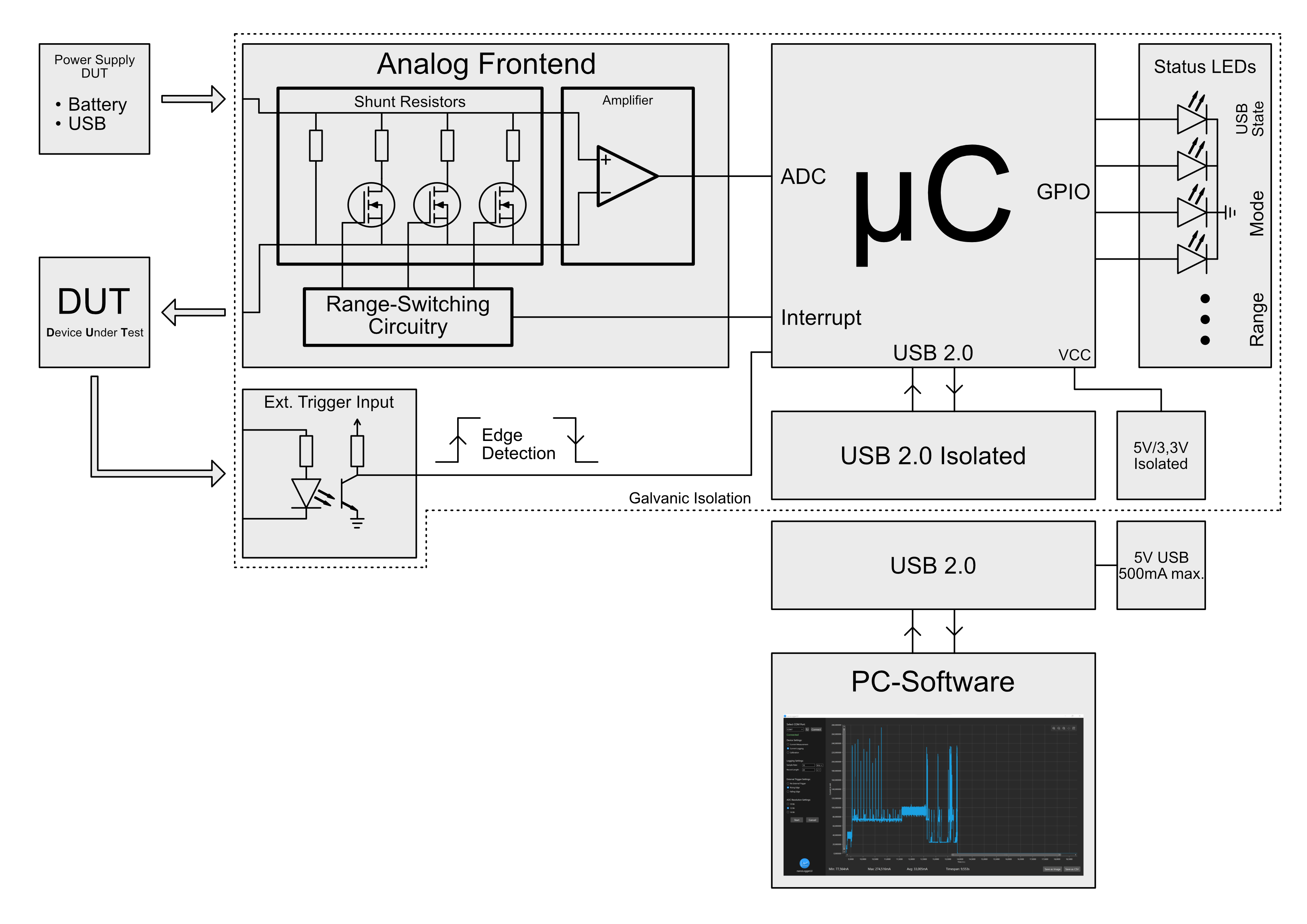
Here is a simplified block diagram of the data logger. To measure the current of a device, the data logger is simply connected in series between the voltage source and the DUT/load.
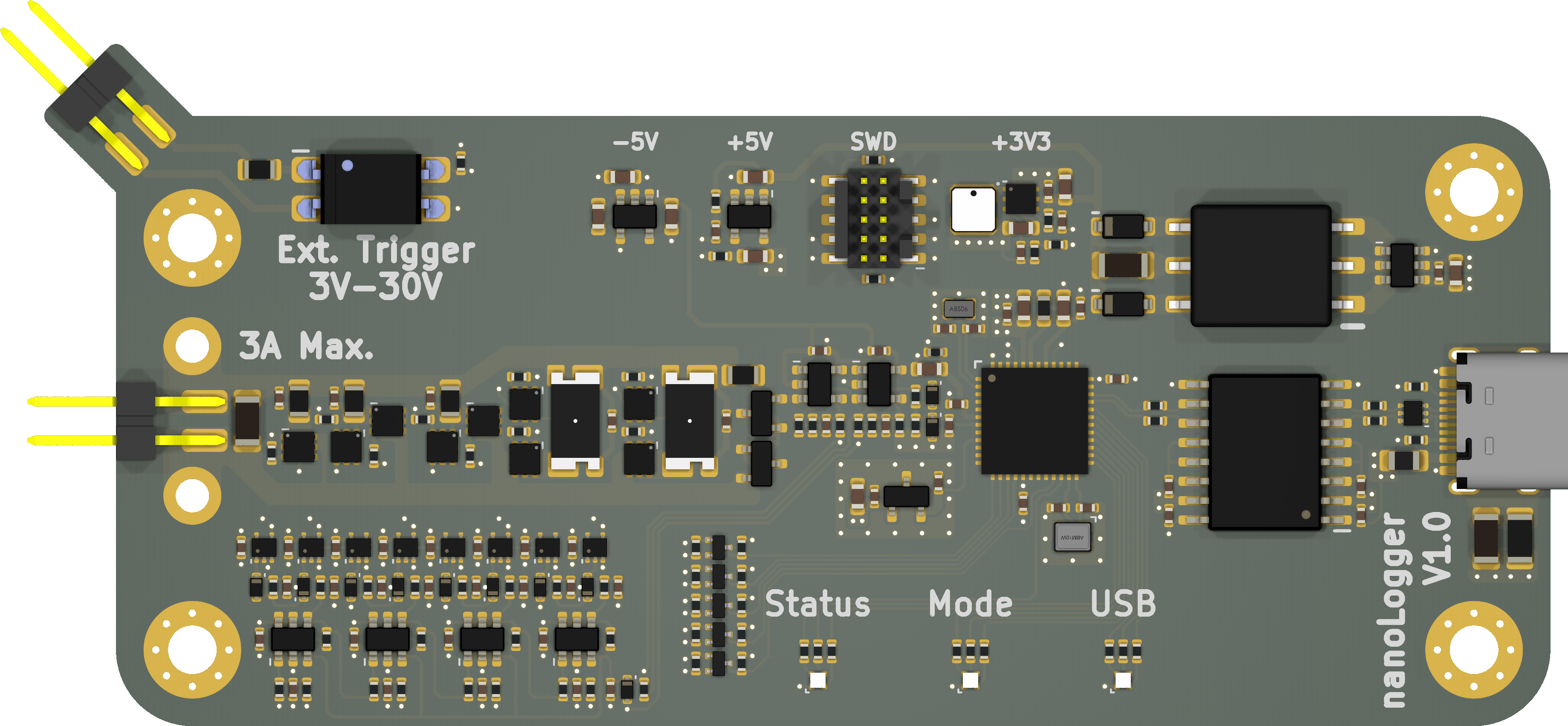
NanoLogger is an open-source printed circuit board by TobiasNetzer, from the TobiasNetzer/nanoLogger repository on GitHub. It is a 4-layer board of 98.7 × 44.7 mm with 221 parts on 150 nets, routed with 1,091 tracks and 240 vias.
It is built around the ATSAMD51G18A-MF, OPA189ID and SN6505BDBV, with the TPS62290DRV, LMV761MF and SN74AHC1G04DBV among its other parts. Its parts include 79 resistors, 70 capacitors, 23 ICs, 16 diodes and 16 transistors. It belongs with the SAM D and SAM boards of this library.


Here is a simplified block diagram of the data logger. To measure the current of a device, the data logger is simply connected in series between the voltage source and the DUT/load.
The current flow creates a small voltage drop across the selected shunt resistor, which is amplified by a factor of 100. The output voltage is then measured by the microcontroller's internal ADC. A change of the current range is also observed by the microcontroller, to correctly convert the measured current.
An external trigger signal can optionally be connected. This allows to start the measurement on a rising or falling edge. Perfect to always have the same starting point of a measurement, for example when the DUT enters active mode.
Status LEDs provide the user with information about the device's current state/mode, for example: logger in standby mode, or data recording in progress.
The captured data is buffered internally in the microcontroller and then transferred to a PC via an isolated USB 2.0 interface.
I've written a very detailed explanation as part of the project documentation. You can read more about it here if you are interested in the design aspects and my thoughts behind them. This is also where you can find all the schematics and technical drawings. The documentation was however written in German.
| Qty | Value | Footprint | References |
|---|---|---|---|
| 33 | 100nF | nanoLogger:Capacitor_0402 | C3, C4, C10, C14, C20, C21, C22, C24, C26, C28, C36, C37, C38, C39, C40, C41 +17 |
| 14 | 68R | nanoLogger:Resistor_0402 | R38, R39, R40, R41, R42, R43, R44, R45, R46, R47, R49, R51, R53, R55 |
| 11 | 1PS79SB30 | nanoLogger:SOD523 | D6, D7, D8, D9, D10, D11, D12, D13, D14, D15, D16 |
| 10 | 10k | nanoLogger:Resistor_0402 | R8, R11, R14, R48, R50, R52, R54, R56, R60, R66 |
| 9 | 1nF | nanoLogger:Capacitor_0402 | C45, C54, C55, C56, C57, C58, C59, C60, C61 |
| 9 | DMN6040SFDE | nanoLogger:UDFN2020-6_Type-E | Q1, Q2, Q3, Q4, Q5, Q6, Q7, Q8, Q9 |
| 8 | 100R | nanoLogger:Resistor_0402 | R72, R73, R74, R75, R76, R77, R78, R79 |
| 7 | 22pF | nanoLogger:Capacitor_0402 | C11, C43, C44, C50, C51, C52, C53 |
| 6 | 10µF | nanoLogger:Capacitor_0603 | C2, C8, C12, C19, C23, C27 |
| 5 | 1k | nanoLogger:Resistor_0402 | R13, R15, R18, R21, R59 |
| 5 | 2N7002T | nanoLogger:SOT-523 | Q12, Q13, Q14, Q15, Q16 |
| 4 | 24R | nanoLogger:Resistor_0402 | R4, R5, R6, R7 |
| 4 | LMV761 | nanoLogger:SOT-23-6 | U12, U13, U14, U15 |
| 4 | MountingHole_M3 | nanoLogger:MountingHole_M3 | H1, H2, H3, H4 |
| 4 | SN74AHC1G04 | nanoLogger:SOT-553 | U16, U17, U18, U23 |
| 3 | 1k5 | nanoLogger:Resistor_0402 | R17, R20, R23 |
| 3 | 1µF | nanoLogger:Capacitor_0603 | C16, C17, C18 |
| 3 | 2k8 | nanoLogger:Resistor_0402 | R16, R19, R22 |
| 3 | SN74AHC1G02 | nanoLogger:SOT-553 | U20, U21, U22 |
| 3 | Wuerth_150044M155260 | nanoLogger:LED_0404 | D3, D4, D5 |
| 2 | 10k 0.05% | nanoLogger:Resistor_0402 | R24, R25 |
| 2 | 10nF | nanoLogger:Capacitor_1206 | C1, C35 |
| 2 | 12pF | nanoLogger:Capacitor_0402 | C32, C33 |
| 2 | 15k | nanoLogger:Resistor_0402 | R61, R67 |
| 2 | 1k 0,05% | nanoLogger:Resistor_0402 | R34, R37 |
| 2 | 2.2µF | nanoLogger:Capacitor_0603 | C13, C15 |
| 2 | 24k | nanoLogger:Resistor_0402 | R63, R69 |
| 2 | 2k2 0,05% | nanoLogger:Resistor_0402 | R32, R35 |
| 2 | 36k | nanoLogger:Resistor_0402 | R64, R70 |
| 2 | 5k1 | nanoLogger:Resistor_0402 | R2, R3 |
| 2 | 6k8 0,05% | nanoLogger:Resistor_0402 | R33, R36 |
| 2 | 750k | nanoLogger:Resistor_0402 | R65, R71 |
| 2 | 7M5 | nanoLogger:Resistor_0402 | R62, R68 |
| 2 | 8pF | nanoLogger:Capacitor_0402 | C30, C31 |
| 2 | MBR0520L | nanoLogger:SOD-123 | D1, D2 |
| 2 | MMBTH10L | nanoLogger:SOT-23 | Q10, Q11 |
| 2 | MountingHole_M2 | nanoLogger:MountingHole_M2 | H5, H6 |
| 2 | OPA189 | nanoLogger:SOT-23-5 | U9, U10 |
| 2 | PinHeader_2_54mm_2pol_smd | nanoLogger:PinHeader_Male_2_54mm_2pin_smd | J3, J4 |
| 1 | 100R 0,05% | nanoLogger:Resistor_0805 | R27 |
| 1 | 100k | nanoLogger:Resistor_0402 | R58 |
| 1 | 100m 0,1% | nanoLogger:Resistor_CSM2512 | R29 |
| 1 | 100pF | nanoLogger:Capacitor_0402 | C34 |
| 1 | 10R 0,05% | nanoLogger:Resistor_0805 | R28 |
| 1 | 10k | nanoLogger:Resistor_0805 | R57 |
| 1 | 10k 0,05% | nanoLogger:Resistor_0805 | R26 |
| 1 | 10m 0,1% | nanoLogger:Resistor_CSM2512 | R30 |
| 1 | 10nF | nanoLogger:Capacitor_0402 | C29 |
| 1 | 10µF | nanoLogger:Capacitor_1206 | C70 |
| 1 | 10µH | nanoLogger:Inductor_0603 | L4 |
| 1 | 182k | nanoLogger:Resistor_0402 | R10 |
| 1 | 1M | nanoLogger:Resistor_1206 | R1 |
| 1 | 1R | nanoLogger:Resistor_0402 | R12 |
| 1 | 2.2µH | nanoLogger:LPS3015 | L2 |
| 1 | 220R | nanoLogger:Resistor_0805 | R31 |
| 1 | 300R 3A | nanoLogger:Inductor_0805 | L1 |
| 1 | 4.7µF | nanoLogger:Capacitor_0603 | C25 |
| 1 | 600R | nanoLogger:Inductor_0402 | L3 |
| 1 | 820k | nanoLogger:Resistor_0402 | R9 |
| 1 | ABM10W-48MHZ | nanoLogger:Abracon_ABM10_2.5x2.0mm | Y1 |
| 1 | ABS06-32.768K | nanoLogger:Abracon_ABS06 | Y2 |
| 1 | ADUM4160 | nanoLogger:SOIC-16W | U2 |
| 1 | ATSAMD51G18A-M | nanoLogger:VQFN-48 | U7 |
| 1 | ISL21080CIH315Z-TK | nanoLogger:SOT-23 | U8 |
| 1 | LP2981IM5X-5.0 | nanoLogger:SOT-23-5 | U5 |
| 1 | PS2533L-1-F3-A | nanoLogger:DIP-4 | U11 |
| 1 | SN6505B | nanoLogger:SOT-23-6 | U3 |
| 1 | SN74AHC1G32 | nanoLogger:SOT-553 | U19 |
| 1 | SWD Header | nanoLogger:SAMTEC_FTSH-105-XX-X-DV | J2 |
| 1 | TPS60400 | nanoLogger:SOT-23-5 | U6 |
| 1 | TPS62290 | nanoLogger:SON-6 | U4 |
| 1 | USBLC6-2P6 | nanoLogger:SOT-666 | U1 |
| 1 | USB_Type_C_Receptacle | nanoLogger:USB_C_Receptacle_HRO_TYPE-C-31-M-12 | J1 |
| 1 | Wuerth_750315371 | nanoLogger:Transformer_Wuerth_750315371 | TR1 |


LEAT-EDGE/ambient-pcb-audiopower
Audio capture and energy management daughterboard PCB for the Ambient project.


borzeman/PzbElectronics
Репозиторий для поддержки версионирования при разработке плат для киоска.
It measures 98.7 × 44.7 mm and has 4 copper layers, 1.53 mm thick.
221 parts, built around the ATSAMD51G18A-MF, OPA189ID, SN6505BDBV and TPS62290DRV. The full list of its parts is on this page, with links to each part's symbol and footprint where PCBKit's library has them.
From the TobiasNetzer/nanoLogger repository on GitHub, at the commit this page was made from: the board is nanoLogger/nanoLogger.kicad_pcb and its schematic nanoLogger/Current_Sensing.kicad_sch. PCBKit opens the board in the browser, with nothing to install.
Its repository states no licence, so its author keeps all rights: ask TobiasNetzer before reusing the design.