2 layers30 × 15 mm
TFHT01
ThunderFly-aerospace/TFHT01
Airborne Humidity and Temperature sensor for UAVs.
34 parts10GPL-3.0

 ThunderFly-aerospace/TFI2CADC011
I2C Analog to digital converter for PixHawk
TFI2CADC01 is an open-source printed circuit board by ThunderFly-aerospace, from the ThunderFly-aerospace/TFI2CADC01 repository on GitHub, published under the GPL-3.0 licence. It is a 2-layer board of 25 × 15 mm with 20 parts on 14 nets, routed with 122 tracks and 27 vias.
It is built around the ADS1115IDGS, MIC5504-3.3YM5 and SM04B-GHS-TB, with the BZX585-B5V6,115-JSM among its other parts. Its parts include 4 capacitors, 4 resistors, 3 diodes, 3 connectors and 2 ICs. It belongs with the sensors and measurement boards of this library.


Compact 4‑channel analog‑to‑digital converter module for Pixhawk‑class autopilots and ThunderFly form‑factor carrier boards. Based on TI ADS1115 (16‑bit Σ‑Δ ADC). Dual Pixhawk JST‑GH I²C ports support in‑line daisy‑chaining.
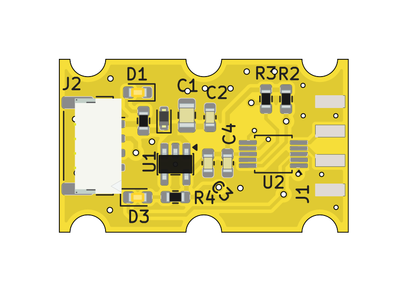
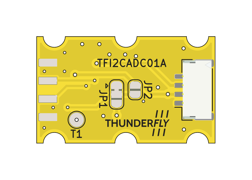
⚠️ Do not exceed 3.3 V on AINx relative to GND.
Pin 1: VBUS +5V
Pin 2: SCL
Pin 3: SDA
Pin 4: GND
Both ports are wired in parallel for pass‑through/daisy‑chain.
Default assembly is 0x48.
| ADDR input | 7‑bit I²C address |
|---|---|
| GND | 0x48 (default) |
| VDD (3.3 V) | 0x49 |
| SDA | 0x4A |
| SCL | 0x4B |
The board provides pads/jumper position for changing the address. See silkscreen near ADDR.
i2c-tools)# Detect
sudo i2cdetect -y 1
# Read a register (conversion register 0x00)
sudo i2cget -y 1 0x48 0x00 wPCB follows the ThunderFly form factor for avionics modules (mounting & stacking compatible with TF carriers). Two JST‑GH side‑by‑side for easy in‑line installation inside UAV wiring harnesses.
The TFI2CADC01 is available from ThunderFly s.r.o. For a commercial quotation, contact us at sale@thunderfly.cz or shop via our Lectronz or Tindie store.
We also offer application‑specific modifications on request. Typical options include alternative input scaling (dividers/shunts), connector or cable variations, pre‑strapped I²C addresses, and simple mounting adaptations. Basic changes are usually provided at no additional cost with an estimated lead time of approximately three weeks.
| Qty | Value | Footprint | References |
|---|---|---|---|
| 2 | 100nF | Capacitor_SMD:C_0603_1608Metric | C2, C4 |
| 2 | 10k | Resistor_SMD:R_0603_1608Metric | R2, R3 |
| 2 | SM04B-GHS-TB | Connector_JST:JST_GH_SM04B-GHS-TB_1x04-1MP_P1.25mm_Horizontal | J2, J3 |
| 1 | 10uF | Capacitor_SMD:C_0805_2012Metric | C1 |
| 1 | 180R | Resistor_SMD:R_0603_1608Metric | R1 |
| 1 | 1uF | Capacitor_SMD:C_0603_1608Metric | C3 |
| 1 | 4k7 | Resistor_SMD:R_0603_1608Metric | R4 |
| 1 | ADS1115IDGS | Package_SO:VSSOP-10_3x3mm_P0.5mm | U2 |
| 1 | ALERT | LED_SMD:LED_0603_1608Metric | D3 |
| 1 | ALERT/RDY | TestPoint:TestPoint_Pad_D2.0mm | T1 |
| 1 | BZX585-B5V6.115 | Diode_SMD:D_SOD-523 | D2 |
| 1 | HEADER_2x04 | Mlab_Pin_Headers:PinHeader_2x04_P2.54mm_Edge_Mount | J1 |
| 1 | LOGO | TF_LOGA:TF 10x4,7 | G*** |
| 1 | MIC5504-3.3YM5 | Package_TO_SOT_SMD:SOT-23-5 | U1 |
| 1 | PWR | LED_SMD:LED_0603_1608Metric | D1 |
| 1 | SolderJumper_2_Open | Jumper:SolderJumper-2_P1.3mm_Open_RoundedPad1.0x1.5mm | JP2 |
| 1 | ~ | Jumper:SolderJumper-3_P1.3mm_Bridged12_RoundedPad1.0x1.5mm | JP1 |
ThunderFly-aerospace/TFHT01
Airborne Humidity and Temperature sensor for UAVs.

ThunderFly-aerospace/TFI2CADT01
I2C address translator module, allows connection of multiple I2C devices with the same address to one bus.

ThunderFly-aerospace/TFRPM01
Revolutions per minute (RPM) meter for UAV, rotors, wheels and engines.

ThunderFly-aerospace/TFI2CEXT01
I2C bus wire length extension module. Enabling the use of more extensive bus interconnection.


ThunderFly-aerospace/TFASPDIMU02
I²C bus differential pressure sensor with IMU and Magnetometer.

ThunderFly-aerospace/TFUNIPAYLOAD01
Universal interface for TF-ATMON sensor payload.
It measures 25 × 15 mm and has 2 copper layers, 1.6 mm thick.
20 parts, built around the ADS1115IDGS, MIC5504-3.3YM5, SM04B-GHS-TB and BZX585-B5V6,115-JSM. The full list of its parts is on this page, with links to each part's symbol and footprint where PCBKit's library has them.
From the ThunderFly-aerospace/TFI2CADC01 repository on GitHub, at the commit this page was made from: the board is hw/sch_pcb/TFI2CADC01.kicad_pcb and its schematic hw/sch_pcb/TFI2CADC01.kicad_sch. PCBKit opens the board in the browser, with nothing to install.
Its repository publishes it under the GPL-3.0 licence: you may reuse it on that licence's terms (keep the author's notice, and for a copyleft licence share your changes alike).