4 layers90.9 × 50.3 mm

 ThunderFly-aerospace/TFUNIPAYLOAD011
Universal interface for TF-ATMON sensor payload.
TFUNIPAYLOAD01 is an open-source printed circuit board by ThunderFly-aerospace, from the ThunderFly-aerospace/TFUNIPAYLOAD01 repository on GitHub, published under the GPL-3.0 licence. It is a 2-layer board of 70.6 × 50.3 mm with 81 parts on 70 nets, routed with 638 tracks and 96 vias.
It is built around the ATMEGA1284P-AU, KPTR-3216SURCK and BC817-25, with the SKRTLAE010, BAS516 and BZX585-B5V6,115-JSM among its other parts. Its parts include 29 resistors, 15 capacitors, 7 diodes, 6 connectors and 3 ICs. It belongs with the sensors and measurement and interfaces and adapters boards and the AVR (ATmega, ATtiny) boards of this library.


Reference design of PX4 interface for generic TF-ATMON compatible payload. The purpose of this design is to connect a sensor to the TF-ATMON system, despite that the sensor does not have any driver in the flight stack (autopilot firmware), but at the same time, it is required for atmospheric measurement.
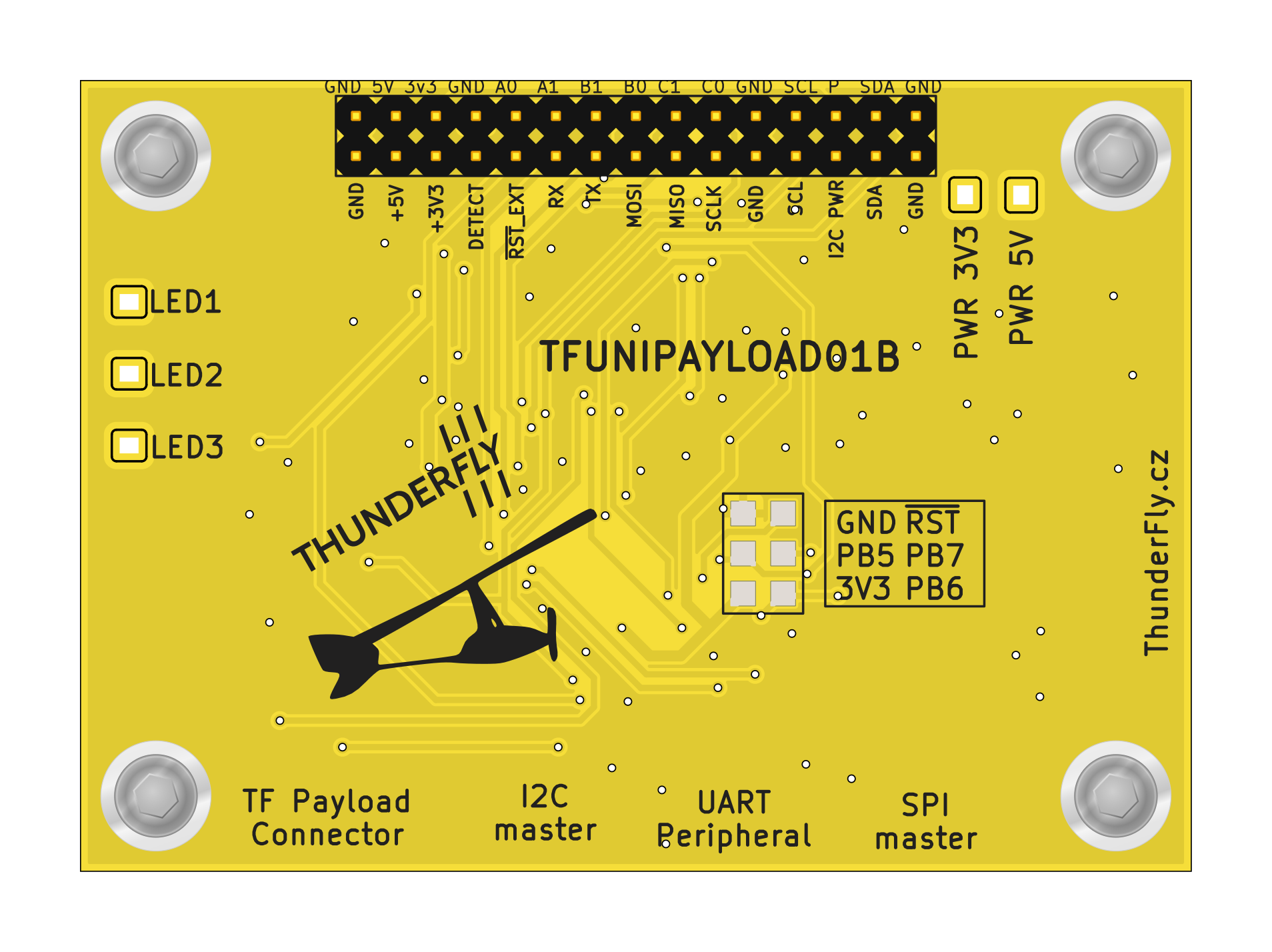
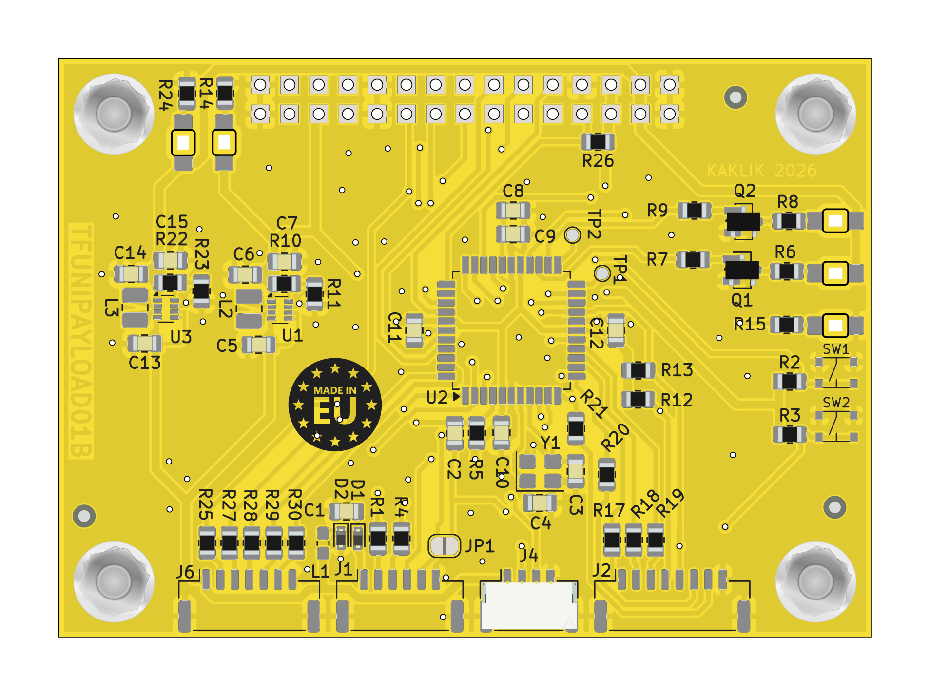
The sensor is connected to the TFUNIPAYLOAD board using a UART, I2C, GPIO, ADC, or SPI interface. ATmega in TFUNIPAYLOAD01 runs the Arduino firmware, which prepares MAVLink messages to be logged and transported to GCS running TF-ATMON infrastructure described in the block schematics.
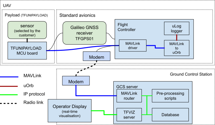
FMU firmware (PX4 or Ardupilot, for example) is capable of logging MAVLink data from the UART (Telemetry Port). Therefore, the “UART Peripheral” connector on TFUNIPAYLOAD01 is intended for connecting a UART-based FMU using the Pixhawk DS-009 telemetry pinout. Typical devices include flight controllers (autopilot) or companion computers.
Pixhawk standard connector pinout is as follows:
| Pin | Signal | Voltage levels | Read/Write | Write |
|---|---|---|---|---|
| 1 (red) | Vcc | +5V | Optional | Optional |
| 2 (blk) | TX (OUT) | +3.3 V | PX4 -> Payload | -- |
| 3 (blk) | RX (IN) | +3.3 V | Payload -> PX4 | Payload -> PX4 |
| 4 (blk) | CTS (IN) | +3.3 V | -- | -- |
| 5 (blk) | RTS (OUT) | +3.3 V | -- | -- |
| 6 (blk) | GND | GND | GND | GND |
For data to be received by the PX4 autopilot, it must have a specific form. Explicitly, it needs to use a serial link with MAVLink v2 packets. In that case, the Tunnel (#385) packets will be stored in the autopilot's log file and forwarded to the GCS. The TFUSBSERIAL01 hardware could be used to easily check for correct wiring.
The following library c_library_v2, which is automatically generated from message definition files, could be used.
There are multiple Arduino-based firmware examples for different use cases.
TFUNIPAYLOAD.ino contains a basic example, which listens to MAVLink messages from the autopilot and sends tunnel packets with random data to the autopilot.
Since message parsing requires a lot of memory, we have prepared an example where only HEARTBEAT and TUNNEL messages are sent. This example does not require a connected TX (from autopilot), and it is, therefore, suitable for MCUs with less memory.
Source code: TFUNIPAYLOAD_MINIMAL.ino
Tunnel packet sending function mav.SendTunnelData(data, sizeof(data), 0, 1, 0); is the main function that enables sending tunnel data to the autopilot. It takes the following as its arguments:
If the data only needs to be logged, the target sysid and compid must match the autopilot’s address, which is usually sysid: 1, compid: 1. If the data has to be logged and sent to GCS, broadcast must be set: sysid: 1, compid: 0 or better sysid: 0, compid: 0.
The autopilot only has a limited amount of storage memory (SD card), and it is therefore necessary to ensure, on the payload’s side, that it does not fill up during the flight. Alternatively, a maximum bandwidth on the MAVLink interface can be set in the autopilot. It is not tested what happens when the level set is exceeded[2021/09].
In the autopilot’s PX4 firmware, it is necessary to correctly set the following parameters (MAV_1_FORWARD and others will be visible only after setting the parameter MAV_1_CONFIG and rebooting the PX4):
| Parametr | Value | Description |
|---|---|---|
| MAV_1_CONFIG | TELEM 2 | The port on which MAVLink packets will be expected. Any free TELEM port can be set |
| MAV_1_FORWARD | 1 | Enable message forwarding from this port |
| MAV_1_RADIO_CTL | 0 | |
| MAV_1_RATE | 0 B/s | |
| SER_TEL2_BAUD | 57600 | It is necessary to configure the port that is set in MAV_1_CONFIG parameter. The setting of the baud rate port. |
How to set the parameters in PX4 is described in manual.
There are several options to find out whether the message sending is working correctly.
The message can be easily viewed live in QGC. For this procedure to function, two conditions must be fulfilled.
Warning: this procedure will not work if the autopilot is connected via a USB cable to the Pixhawk's USB port.
After opening QGC, connect the autopilot to the computer (via RF modem or an external USB converter connected to the serial port). Once the autopilot is connected, live data (such as autopilot attitude) will become visible. A subsequent click on the QGC logo in the top left corner will open a menu where you select Analyze tools and then open MAVLink inspector in order to see a list of all messages.

The list of messages, when functioning correctly, should contain TUNNEL messages.
An advantage of connecting via PX4 console lies in its independence from broadcasting settings and the possibility of checking whether the message is received and parsed by the autopilot. If the message is visible here (and the logging is enabled), it is at the same time already logged. With this procedure, a USB cable connection to the autopilot can be used.
Autopilot console can be entered using the following Python script or using QGC.
Analyze tools, and choosing a console.The received message can then be retrieved using the following command:
listener mavlink_tunnel
The command displays the current tunnel message. Adding the -n 100` parameter will cause a listing of 100 messages (and the new message will display by itself).
If the communication is working properly, the output should look like this:

The tunnel message can be logged into autopilot in a standard uLog format. However, because tools like Flight review are unable to display such data format, it is necessary to overcome this problem using a suitable tool. One option is using the PlotJuggler. Another possibility for opening the log is the Jupiter notebook.
| Qty | Value | Footprint | References |
|---|---|---|---|
| 14 | 100R | Resistor_SMD:R_0805_2012Metric | R1, R4, R6, R15, R17, R18, R19, R20, R21, R25, R27, R28, R29, R30 |
| 8 | 10k | Resistor_SMD:R_0805_2012Metric | R2, R3, R5, R7, R9, R12, R13, R26 |
| 4 | 100nF | Capacitor_SMD:C_0805_2012Metric | C9, C10, C11, C12 |
| 4 | HOLE | Mlab_Mechanical:MountingHole_3mm | M1, M2, M3, M4 |
| 3 | 10u | Capacitor_SMD:C_0805_2012Metric | C7, C8, C15 |
| 3 | 180R | Resistor_SMD:R_0805_2012Metric | R8, R14, R24 |
| 3 | Fiducial | Fiducial:Fiducial_1mm_Mask2mm | FID1, FID2, FID3 |
| 3 | RED | Mlab_D:LED_1206_mill | D4, D5, D7 |
| 2 | 15p | Capacitor_SMD:C_0805_2012Metric | C3, C4 |
| 2 | 1uH - DFE252012P-1R0M=P2 | Inductor_SMD:L_1008_2520Metric | L2, L3 |
| 2 | 22u | Capacitor_SMD:C_0805_2012Metric | C5, C13 |
| 2 | 47u | Capacitor_SMD:C_0805_2012Metric | C6, C14 |
| 2 | 91k | Resistor_SMD:R_0805_2012Metric | R11, R23 |
| 2 | BC817-25 | Package_TO_SOT_SMD:SOT-23 | Q1, Q2 |
| 2 | SKRTLAE010 | Mlab_SW:KMT031 NGJ LHS C&K | SW1, SW2 |
| 2 | TPS631000DRLR | Package_TO_SOT_SMD:SOT-583-8 | U1, U3 |
| 1 | 10uF | Capacitor_SMD:C_0805_2012Metric | C1 |
| 1 | 4u7 | Capacitor_SMD:C_0805_2012Metric | C2 |
| 1 | 511k | Resistor_SMD:R_0805_2012Metric | R10 |
| 1 | 8 MHz | Crystal:Crystal_SMD_3225-4Pin_3.2x2.5mm | Y1 |
| 1 | 806k | Resistor_SMD:R_0805_2012Metric | R22 |
| 1 | ATMEGA1284P-AU | Package_QFP:TQFP-44_10x10mm_P0.8mm | U2 |
| 1 | BAS516 | Diode_SMD:D_SOD-523 | D1 |
| 1 | BLUE | Mlab_D:LED_1206_mill | D3 |
| 1 | BZX585-B5V6.115 | Diode_SMD:D_SOD-523 | D2 |
| 1 | GREEN | Mlab_D:LED_1206_mill | D6 |
| 1 | HEADER_2x03 | Mlab_Pin_Headers:SMD_2x03_WO_paste | J3 |
| 1 | HEADER_2x15 | Mlab_Pin_Headers:Straight_2x15 | J5 |
| 1 | LOGO | LOGO | G*** |
| 1 | LOGO | TF_LOGA:TF | G1 |
| 1 | LOGO | MLAB_LOGA:Made_in_EU | G*** |
| 1 | NL03KT330 | Inductor_SMD:L_0603_1608Metric_Pad1.05x0.95mm_HandSolder | L1 |
| 1 | PC3 | TestPoint:TestPoint_Pad_D1.0mm | TP1 |
| 1 | PC4 | TestPoint:TestPoint_Pad_D1.0mm | TP2 |
| 1 | SM04B-GHS-TB | Connector_JST:JST_GH_SM04B-GHS-TB_1x04-1MP_P1.25mm_Horizontal | J4 |
| 1 | SM06B-GHS-TB | Connector_JST:JST_GH_SM06B-GHS-TB_1x06-1MP_P1.25mm_Horizontal | J1 |
| 1 | SM07B-GHS-TB | Connector_JST:JST_GH_SM07B-GHS-TB_1x07-1MP_P1.25mm_Horizontal | J6 |
| 1 | SM08B-GHS-TB | Connector_JST:JST_GH_SM08B-GHS-TB_1x08-1MP_P1.25mm_Horizontal | J2 |
| 1 | SolderJumper_2_Open | Jumper:SolderJumper-2_P1.3mm_Open_RoundedPad1.0x1.5mm | JP1 |

kanha2907/Gps-using-neom9n-
Compact GPS breakout board based on the u-blox NEO-M9N module. Includes support circuitry for battery-backed operation, LEDs, and passives—designed for low-power embedded GPS applications.

ThunderFly-aerospace/TFRPM01
Revolutions per minute (RPM) meter for UAV, rotors, wheels and engines.


mlab-modules/BATDATUNIT01
Multiple parallel Li-ion 18650 battery cell module with BMS and data storage with MCU control.

mlab-modules/BLE02
Bluetooth 4.1 controller for UART HCI-based BLE and BR/EDR communication with external host MCU.
It measures 70.6 × 50.3 mm and has 2 copper layers, 1.66 mm thick.
81 parts, built around the ATMEGA1284P-AU, KPTR-3216SURCK, BC817-25 and SKRTLAE010. The full list of its parts is on this page, with links to each part's symbol and footprint where PCBKit's library has them.
From the ThunderFly-aerospace/TFUNIPAYLOAD01 repository on GitHub, at the commit this page was made from: the board is hw/sch_pcb/TFUNIPAYLOAD01.kicad_pcb and its schematic hw/sch_pcb/TFUNIPAYLOAD01.kicad_sch. PCBKit opens the board in the browser, with nothing to install.
Its repository publishes it under the GPL-3.0 licence: you may reuse it on that licence's terms (keep the author's notice, and for a copyleft licence share your changes alike).