2 layers120 × 64 mm
Sensor module
HasiKe/Hayabusa
Eigenbau-Motorsteuerung und Umbauprojekte für die Suzuki Hayabusa der ersten Generation (1999–2007).
138 parts

 Rennaafi/stm32g474-dev-board
4-layer STM32G474RE dev board (Nucleo-64 headers, USB-C, CAN-FD, STDC14) designed in KiCad 9: schematic, PCB layout, Gerbers & BOM
STM32G474 Dev v3 is an open-source printed circuit board by Rennaafi, from the Rennaafi/stm32g474-dev-board repository on GitHub, published under the MIT licence. It is a 4-layer board of 66.7 × 66.2 mm with 77 parts on 102 nets, routed with 1,315 tracks and 387 vias.
It is built around the MCP2562FD-E/SN, AP2112K-3.3 and USBLC6-2SC6, with the NUP2105L among its other parts. Its parts include 20 capacitors, 12 connectors, 10 resistors, 4 ICs and 4 diodes. It belongs with the microcontroller boards boards and the STM32 boards of this library.


A 4-layer STM32G474RE (LQFP-64) development board designed in KiCad 9 and finalised in KiCad 10. It follows the NUCLEO-64 header layout (ST morpho CN7/CN10 plus Arduino Uno R3 headers) and adds a native USB-C port, a CAN-FD transceiver, an STDC14 debug connector and four corner mounting holes. There is no on-board ST-LINK; debugging uses an external STLINK-V3 on the STDC14 connector.
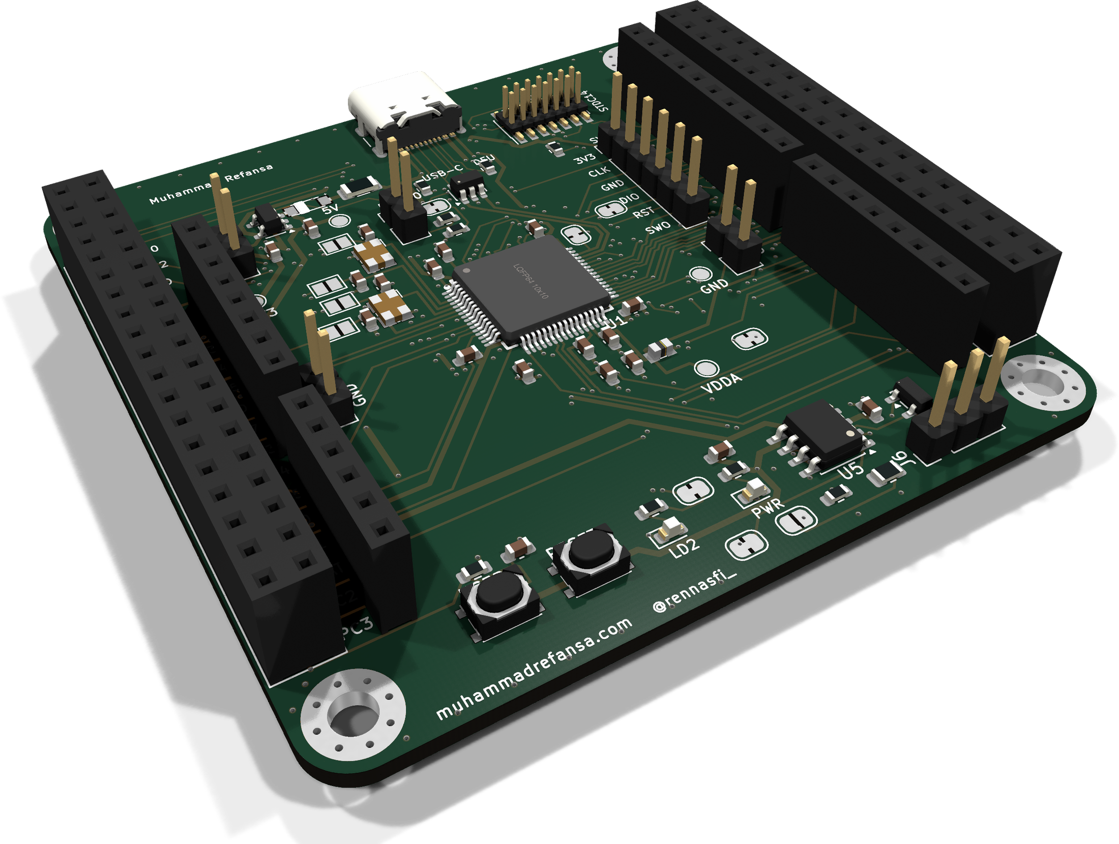
Status: schematic and layout are complete (ERC 0 errors · 0 unconnected · 4 DRC errors, all vendor-footprint hole clearance in the USB-C connector, see
waivers.md). The slides from the KCCI PCB Design final presentation are indocs/presentation/. See Known limitations and Before ordering.
J6. Needs +5 V (USB or the 5 V input).JP6 in the MCU supply.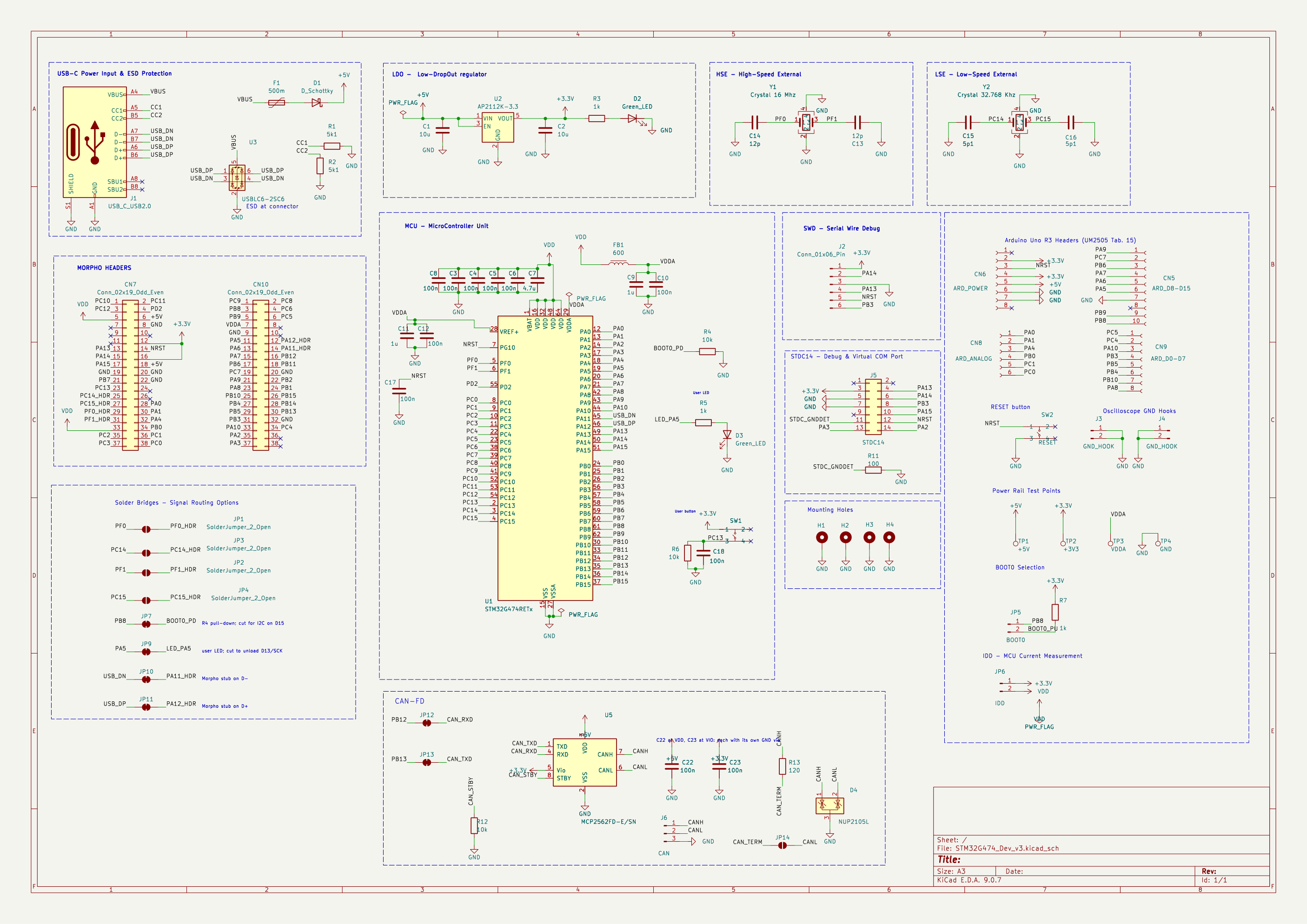
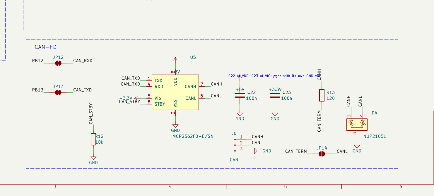
The CAN-FD block:
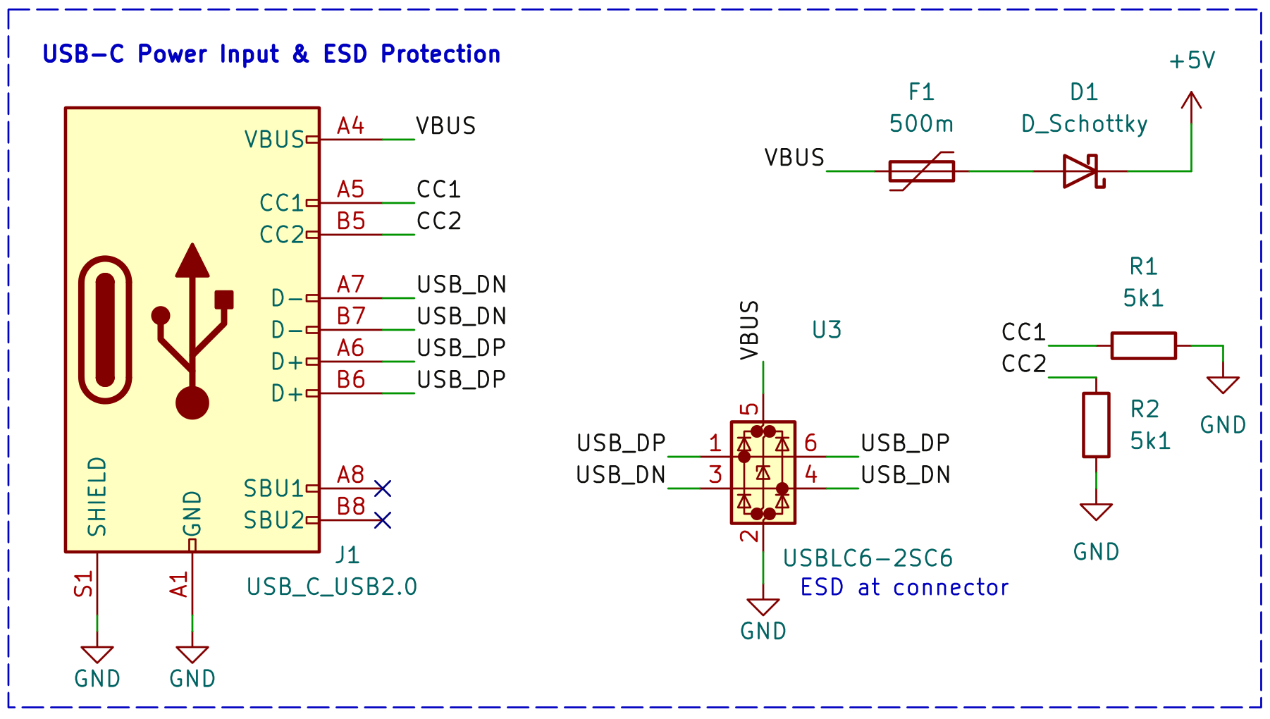
Cropped views of each section (as used in the presentation) are in Media/schematic/:
| Power input + ESD | LDO |
|---|---|
 | 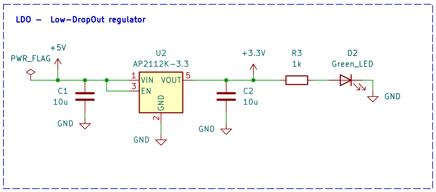 |
| MCU | HSE / LSE crystals |
|---|---|
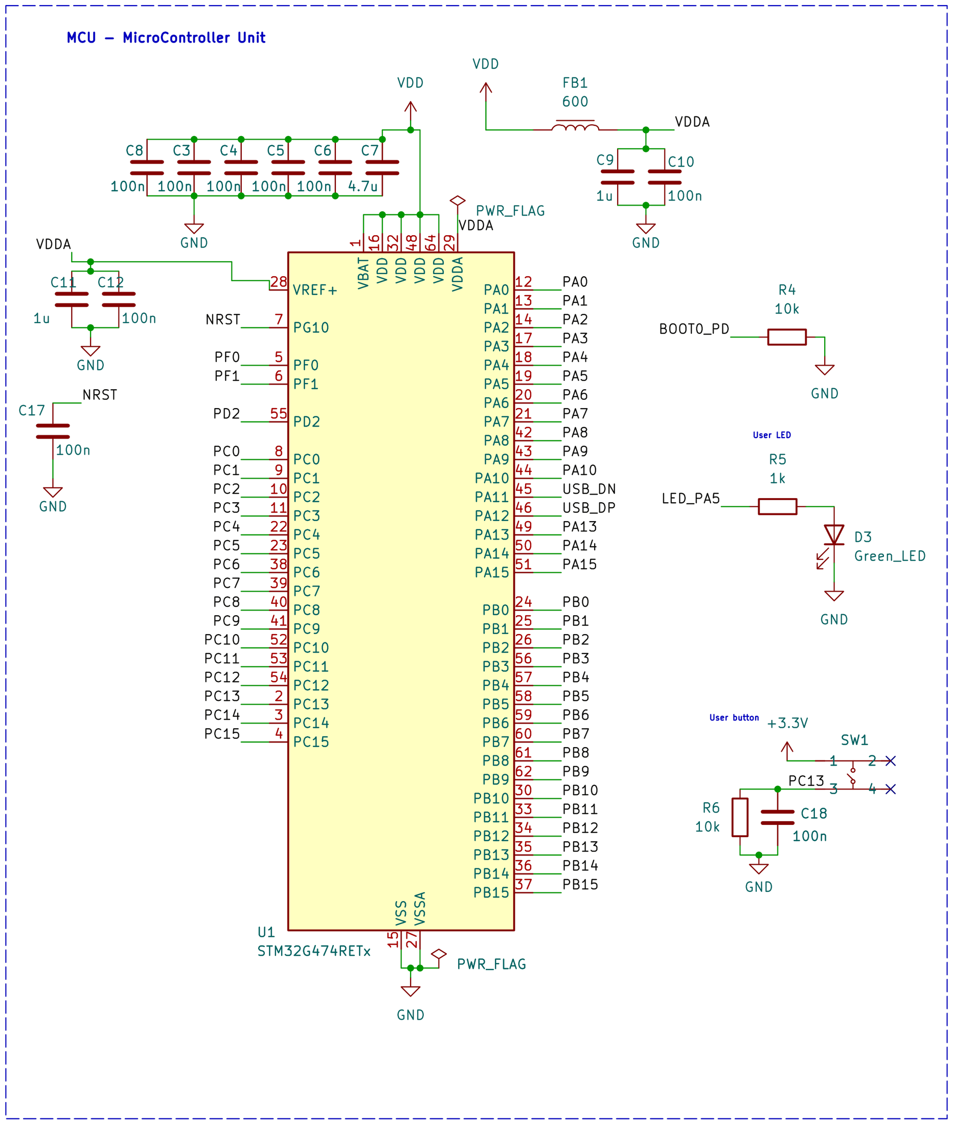 | 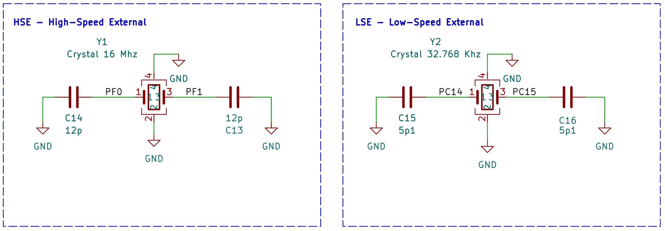 |
| CAN-FD | SWD + STDC14 debug |
|---|---|
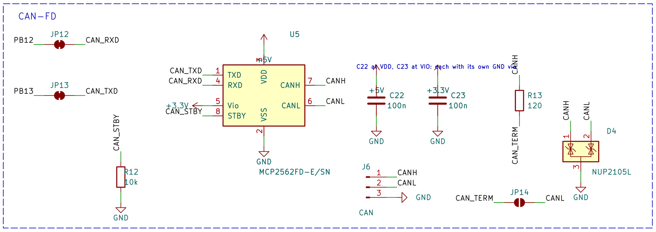 | 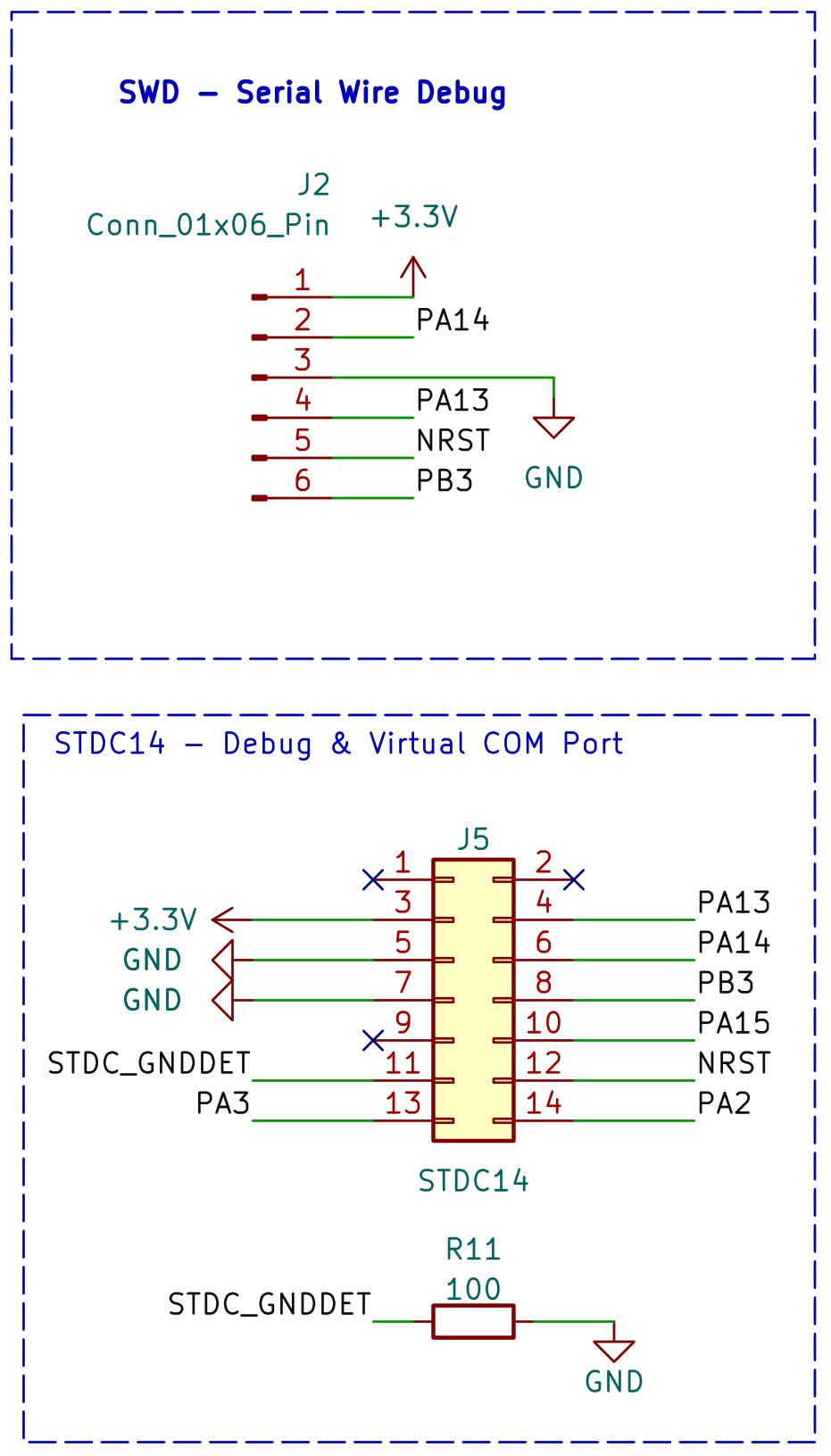 |
Top and bottom (the bottom silkscreen carries the pin names of the headers):
| Top | Bottom |
|---|---|
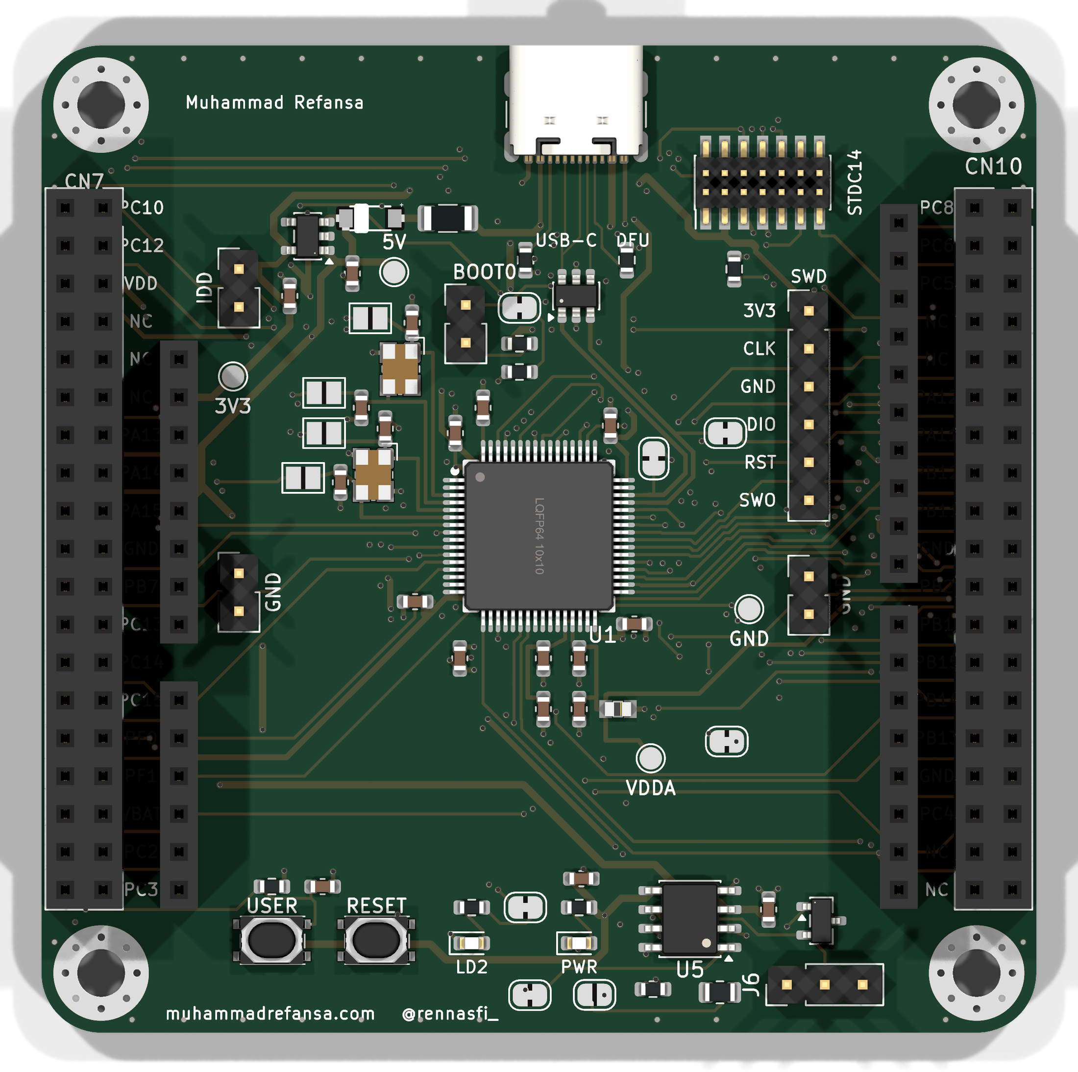 | 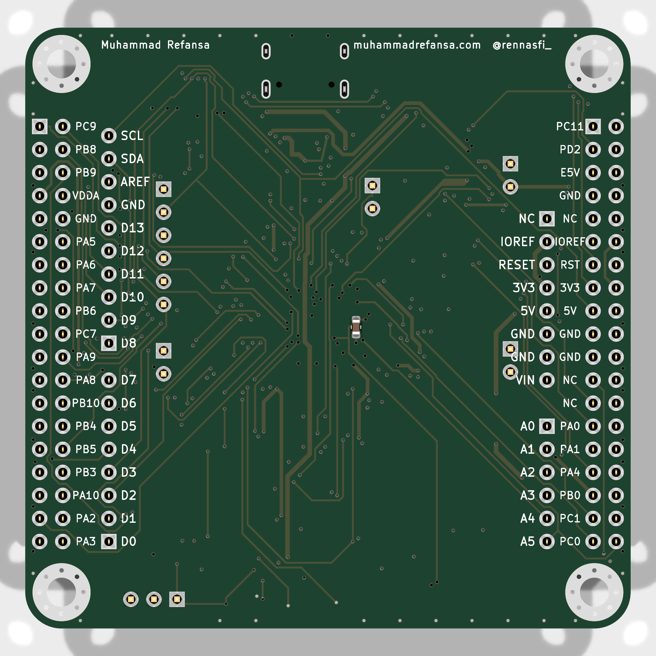 |
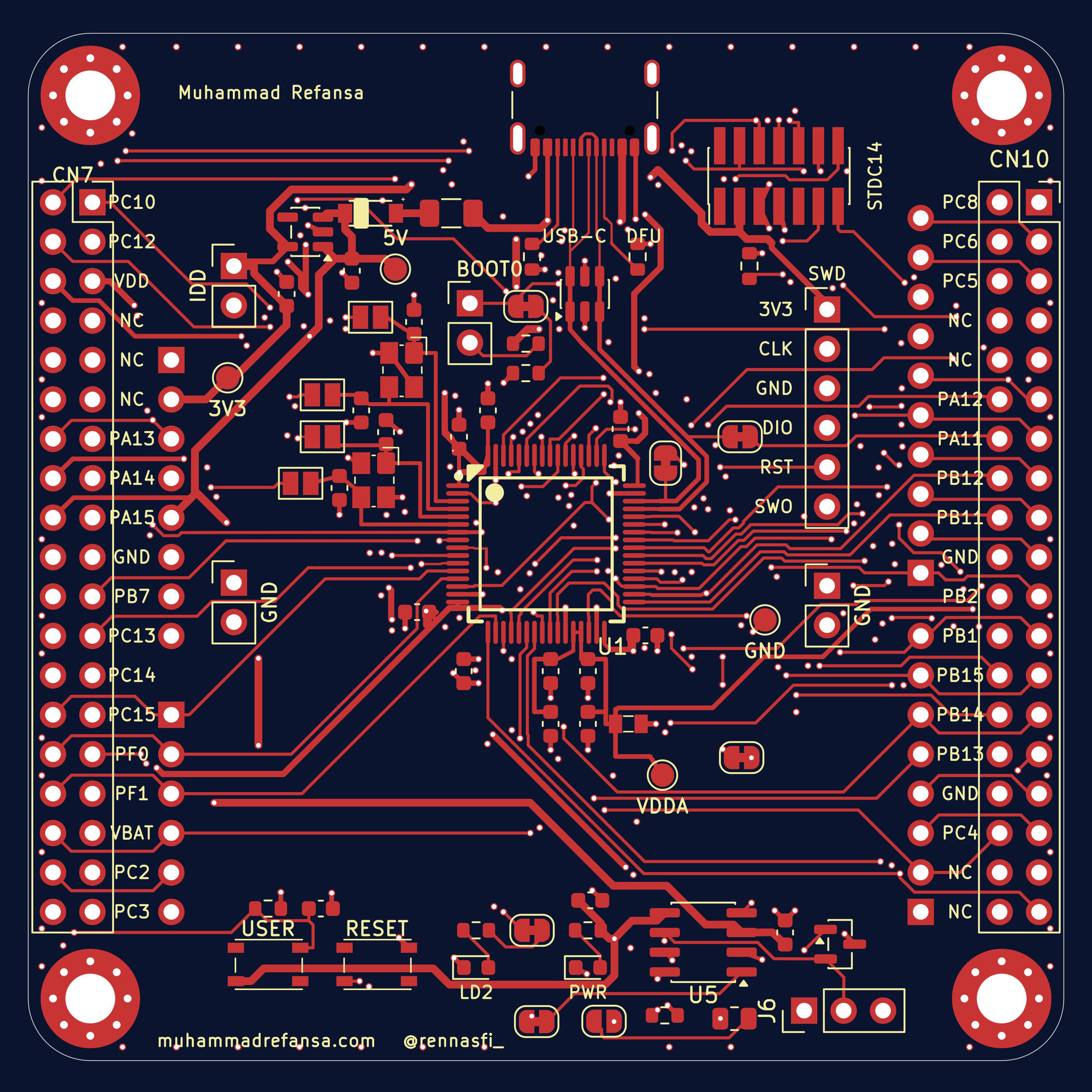
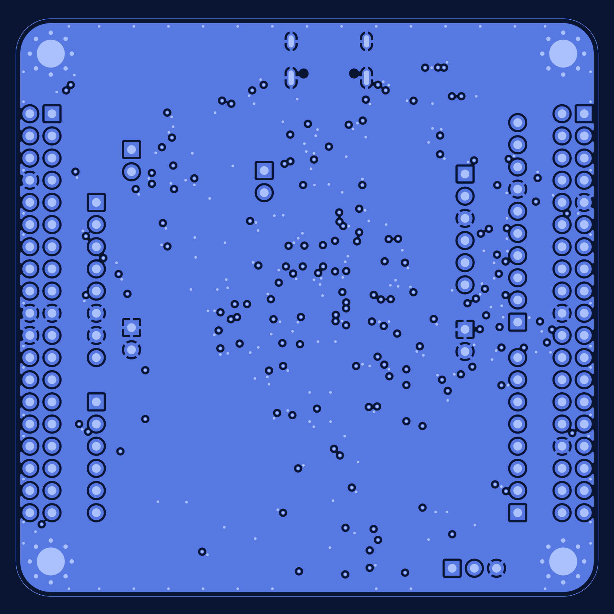
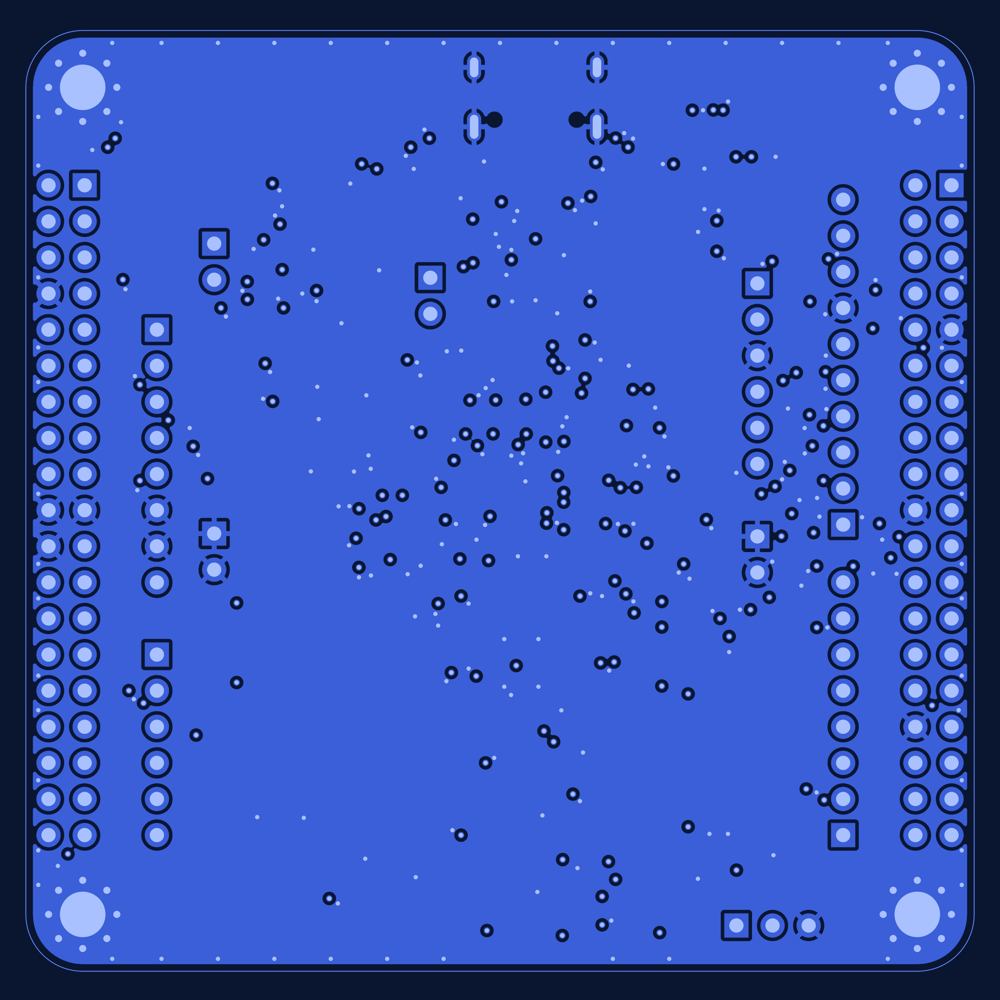
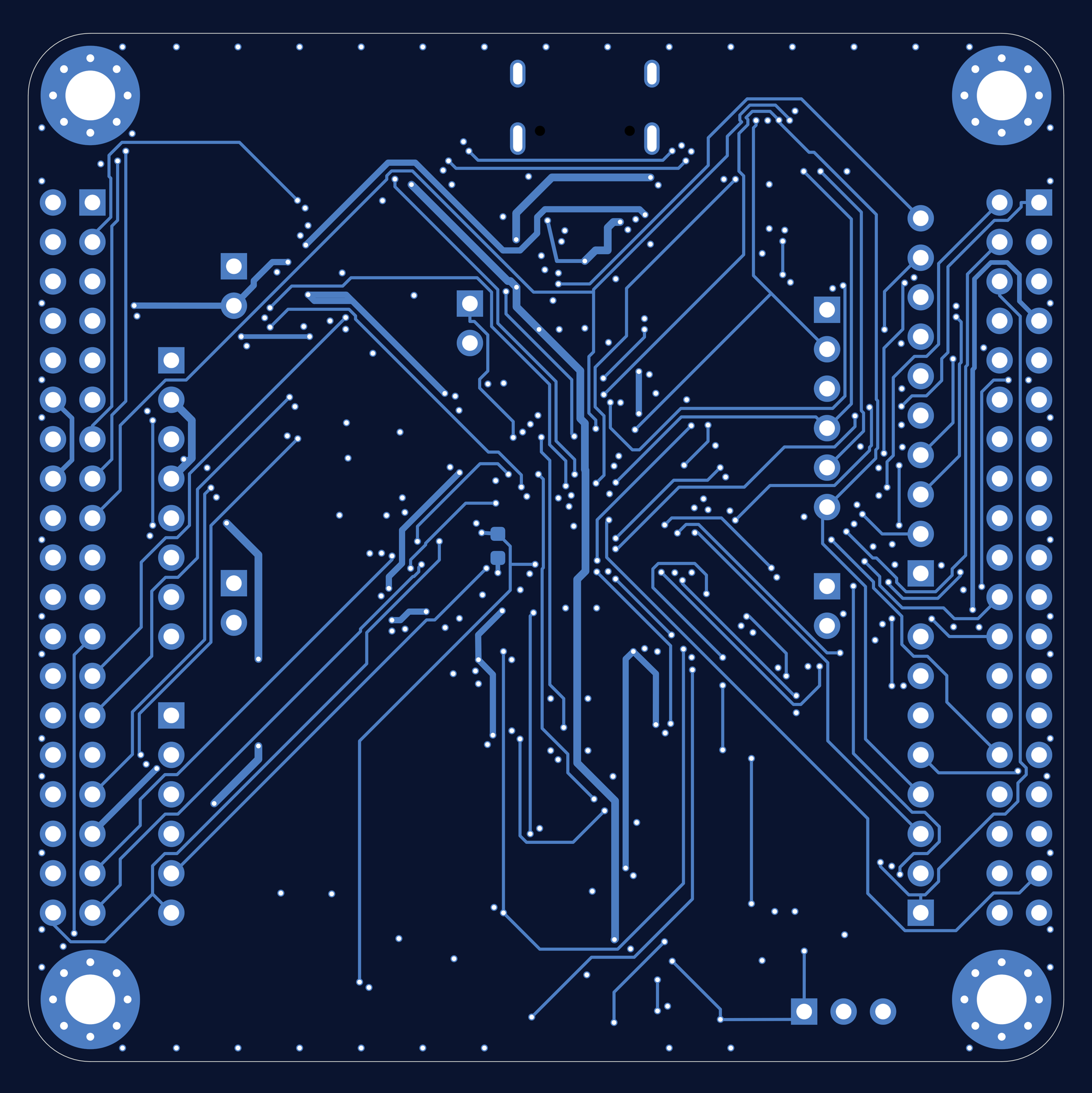
Floorplan (both signal layers) and the four layers on their own:
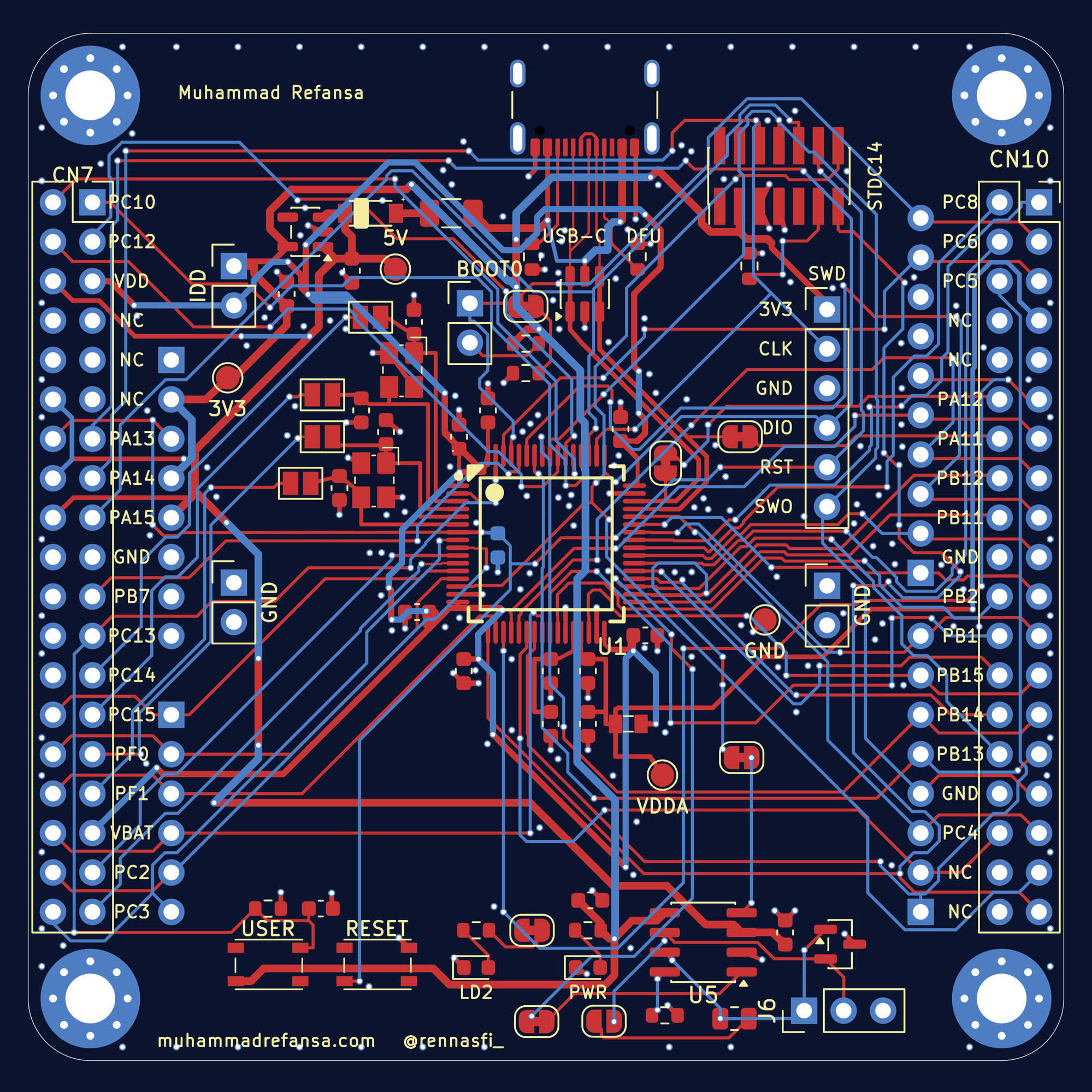
| L1 signal + parts | L2 GND |
|---|---|
 |  |
| L3 GND | L4 signal |
|---|---|
 |  |
| Jumper | Default | Purpose |
|---|---|---|
| JP6 | 2-pin header (fit a jumper) | IDD measurement: the MCU supply runs through it; remove the jumper and insert an ammeter to measure current |
| JP7 | bridged | BOOT0 pull-down; cut it to use D15/SCL (set nSWBOOT0 = 0 first) |
| JP9 | bridged | user LED on D13/SCK; cut to unload that pin |
| JP10 / JP11 | bridged | USB D-/D+ stubs on the PA11/PA12 morpho pins; cut to remove the stubs |
| JP12 / JP13 | bridged | CAN RXD/TXD on PB12/PB13; cut to get those morpho pins back |
| JP14 | open | 120 ohm CAN termination; bridge only on the two end nodes of a bus |
scripts/zdiff.py reproduces the estimate. It is a closed-form estimate, not a field solver result.hole_clearance between the GND shield pads of the GCT USB4105 footprint and its own locating peg (0.194 mm against the 0.25 mm board rule). Warnings are silkscreen and library-link items. 0 unconnected items. See docs/reports/waivers.md.BOM/BOM.csv has no manufacturer part numbers, and BOM/CPL.csv rotations may need the fab's preview correction (SOIC-8, SOT-23, USB-C).| Area | NUCLEO-G474RE | This board |
|---|---|---|
| USB | MCU USB not brought to a connector on the board | Native USB-C on PA11/PA12 with ESD protection and DFU |
| CAN | FDCAN available on the MCU, no transceiver | MCP2562FD transceiver, ESD protection, termination option, on FDCAN2 |
| Debug | On-board ST-LINK | STDC14 connector for an external STLINK-V3 |
| Layout | n/a | 4-layer S/GND/GND/S, GND-referenced signal layers, USB pair routed for about 90 ohm |
| Flexibility | Solder bridges | Isolation jumpers for BOOT0, LED, USB stubs and CAN pins |
| Mechanics | n/a | Four corner M3 plated holes, rounded corners; morpho and Arduino headers kept |
.
├── STM32G474_Dev_v3.kicad_pro    # KiCad project
├── STM32G474_Dev_v3.kicad_sch    # Schematic
├── STM32G474_Dev_v3.kicad_pcb    # PCB layout (KiCad 10 file format)
├── Gerber/                       # Gerbers, drill files, job file (+ upload-ready zip)
├── BOM/                          # BOM.csv and CPL.csv (pick-and-place)
├── Media/                        # Renders, schematic images, per-layer views
├── docs/presentation/            # Final presentation slides (PDF)
├── docs/reports/                 # ERC and DRC reports, notes on the DRC results
└── scripts/zdiff.py # USB pair impedance estimateKCCI symbol/footprint library (STM32G474RE, crystals, buttons, ferrite, polyfuse, Schottky). Those symbols and footprints are embedded in the schematic and board, so the project opens and checks cleanly without the library; the library itself is not included.${KICAD9_3DMODEL_DIR}); the 3D render in Media/ was made with local models.| Qty | Value | Footprint | References |
|---|---|---|---|
| 11 | 100n | Capacitor_SMD:C_0603_1608Metric | C3, C4, C5, C6, C8, C10, C12, C17, C18, C22, C23 |
| 6 | Bridged | Jumper:SolderJumper-2_P1.3mm_Bridged_RoundedPad1.0x1.5mm | JP7, JP9, JP10, JP11, JP12, JP13 |
| 4 | MountingHole_Pad | MountingHole:MountingHole_3.2mm_M3_Pad_Via | H1, H2, H3, H4 |
| 4 | SolderJumper_2_Open | Jumper:SolderJumper-2_P1.3mm_Open_Pad1.0x1.5mm | JP1, JP2, JP3, JP4 |
| 3 | 10k | Resistor_SMD:R_0603_1608Metric | R4, R6, R12 |
| 3 | 1k | Resistor_SMD:R_0603_1608Metric | R3, R5, R7 |
| 2 | 10u | Capacitor_SMD:C_0603_1608Metric | C1, C2 |
| 2 | 12p | Capacitor_SMD:C_0603_1608Metric | C13, C14 |
| 2 | 1u | Capacitor_SMD:C_0603_1608Metric | C9, C11 |
| 2 | 5k1 | Resistor_SMD:R_0603_1608Metric | R1, R2 |
| 2 | 5p1 | Capacitor_SMD:C_0603_1608Metric | C15, C16 |
| 2 | Conn_02x19_Odd_Even | Connector_PinSocket_2.54mm:PinSocket_2x19_P2.54mm_Vertical | CN7, CN10 |
| 2 | GND_HOOK | Connector_PinHeader_2.54mm:PinHeader_1x02_P2.54mm_Vertical | J3, J4 |
| 2 | Green_LED | LED_SMD:LED_0603_1608Metric | D2, D3 |
| 1 | +3V3 | TestPoint:TestPoint_Pad_D1.5mm | TP2 |
| 1 | +5V | TestPoint:TestPoint_Pad_D1.5mm | TP1 |
| 1 | 100 | Resistor_SMD:R_0603_1608Metric | R11 |
| 1 | 120 | Resistor_SMD:R_0805_2012Metric | R13 |
| 1 | 4.7u | Capacitor_SMD:C_0603_1608Metric | C7 |
| 1 | 500m | KCCI:PolyFuse_1206_3216Metric | F1 |
| 1 | 600 | KCCI:BLM18PG121SN1D | FB1 |
| 1 | AP2112K-3.3 | Package_TO_SOT_SMD:SOT-23-5 | U2 |
| 1 | ARD_ANALOG | Connector_PinSocket_2.54mm:PinSocket_1x06_P2.54mm_Vertical | CN8 |
| 1 | ARD_D0-D7 | Connector_PinSocket_2.54mm:PinSocket_1x08_P2.54mm_Vertical | CN9 |
| 1 | ARD_D8-D15 | Connector_PinSocket_2.54mm:PinSocket_1x10_P2.54mm_Vertical | CN5 |
| 1 | ARD_POWER | Connector_PinSocket_2.54mm:PinSocket_1x08_P2.54mm_Vertical | CN6 |
| 1 | BOOT0 | Connector_PinHeader_2.54mm:PinHeader_1x02_P2.54mm_Vertical | JP5 |
| 1 | CAN | Connector_PinHeader_2.54mm:PinHeader_1x03_P2.54mm_Vertical | J6 |
| 1 | Conn_01x06_Pin | Connector_PinHeader_2.54mm:PinHeader_1x06_P2.54mm_Vertical | J2 |
| 1 | Crystal 16 Mhz | KCCI:TSX-3225 | Y1 |
| 1 | Crystal 32.768 Khz | KCCI:TSX-3225 | Y2 |
| 1 | D_Schottky | KCCI:Schottky Diode_B5819W-TP_SOD3716X135N | D1 |
| 1 | GND | TestPoint:TestPoint_Pad_D1.5mm | TP4 |
| 1 | IDD | Connector_PinHeader_2.54mm:PinHeader_1x02_P2.54mm_Vertical | JP6 |
| 1 | MCP2562FD-E/SN | Package_SO:SOIC-8_3.9x4.9mm_P1.27mm | U5 |
| 1 | NUP2105L | Package_TO_SOT_SMD:SOT-23 | D4 |
| 1 | RESET | KCCI:button_434133025816 | SW2 |
| 1 | STDC14 | Connector_PinHeader_1.27mm:PinHeader_2x07_P1.27mm_Vertical_SMD | J5 |
| 1 | STM32G474RETx | KCCI:STM32G474RE | U1 |
| 1 | Term | Jumper:SolderJumper-2_P1.3mm_Open_RoundedPad1.0x1.5mm | JP14 |
| 1 | USBLC6-2SC6 | Package_TO_SOT_SMD:SOT-23-6 | U3 |
| 1 | USB_C_USB2.0 | Connector_USB:USB_C_Receptacle_GCT_USB4105-xx-A_16P_TopMnt_Horizontal | J1 |
| 1 | VDDA | TestPoint:TestPoint_Pad_D1.5mm | TP3 |
| 1 | ~ | KCCI:button_434133025816 | SW1 |
HasiKe/Hayabusa
Eigenbau-Motorsteuerung und Umbauprojekte für die Suzuki Hayabusa der ersten Generation (1999–2007).

sujaygouda123/foc-control
BLDC field-oriented-control board for a humanoid robot actuator. KiCad 10, Ø80 mm, 8 layers, 1.6 mm.


BlueJayRacing/22xt_kicad
As a summary, you should be using KiCad Version 9.0. All project will be modular, and you should be storing all your step files, symbols, & footprints within the created folders.


mihircn/stm32-usb-can-fd-adapter
STM32G0B1-based USB-to-CAN FD adapter designed in KiCad.

trnila/stm32_can_lin
Set nSWBOOT0 to 0 using STM32CubeProgrammer for the first time, then connect the debugger and flash the device:

robotical/axiom-thermocouple
Thermocouple amp + microcontroller and JST SH / axiom magnetic connectors
It measures 66.7 × 66.2 mm and has 4 copper layers, 1.6 mm thick.
77 parts, built around the MCP2562FD-E/SN, AP2112K-3.3, USBLC6-2SC6 and NUP2105L. The full list of its parts is on this page, with links to each part's symbol and footprint where PCBKit's library has them.
From the Rennaafi/stm32g474-dev-board repository on GitHub, at the commit this page was made from: the board is STM32G474_Dev_v3.kicad_pcb and its schematic STM32G474_Dev_v3.kicad_sch. PCBKit opens the board in the browser, with nothing to install.
Its repository publishes it under the MIT licence: you may reuse it on that licence's terms (keep the author's notice, and for a copyleft licence share your changes alike).