2 layers63.5 × 43 mm
OSR RN
Open-Things-Network/lora-dev-board
Uniwersalna platforma sprzętowa na warsztaty i do prototypowania
77 parts6MIT

 trnila/stm32_can_lin
Set nSWBOOT0 to 0 using STM32CubeProgrammer for the first time, then connect the debugger and flash the device:
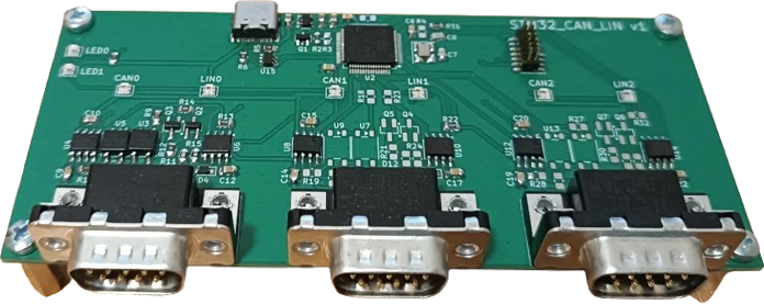
Stm32 can lin is an open-source printed circuit board by trnila, from the trnila/stm32_can_lin repository on GitHub. It is a 2-layer board of 125.3 × 55.3 mm with 103 parts on 131 nets, routed with 726 tracks and 212 vias.
It is built around the EPR411A064000EZ, AP2112K-3.3 and USBLC6-2SC6, with the WS2812B-2020, MMBT2222A and NUP2105L among its other parts. Its parts include 30 resistors, 24 capacitors, 17 diodes, 15 ICs and 7 transistors. It belongs with the STM32 boards of this library.


STM32G4xx firmware written in Rust using the Embassy framework that bridges CAN-FD buses to Linux via USB using the gs_usb driver and socketCAN interface.
Install Rust via rustup.rs.
Set nSWBOOT0 to 0 using STM32CubeProgrammer for the first time, then connect the debugger and flash the device:
$ cargo run --releaseThree socketCAN interfaces will appear, for example as can0, can1, and can2.
You can configure them using ip command:
$ sudo ip link set can0 type can bitrate 500000
$ sudo ip link set can0 up
After that, you can start sending and receiving CAN frames:
$ candump can0
$ cansend can0 123#abcdAll configurations must be done while the interface is in the down state.
$ sudo ip link set can0 downAfter the configuration, bring the interface up.
Set CAN to 500 Kbps and CAN-FD to 1 Mbps:
$ sudo ip link set can0 type can bitrate 500000 fd on dbitrate 1000000Termination resistor can be enabled in configuration mode via:
$ sudo ip link set can0 down
$ sudo ip link set can0 type can bitrate 500000 termination 120
$ sudo ip link set can0 upConfigure udev rules (/etc/udev/rules.d/91-scan.rules) for persistent interface names:
SUBSYSTEM=="net", ENV{ID_SERIAL}=="trnila_STM32_CAN_LIN_1", ATTR{dev_id}=="0x0", NAME="scan0"
SUBSYSTEM=="net", ENV{ID_SERIAL}=="trnila_STM32_CAN_LIN_1", ATTR{dev_id}=="0x1", NAME="scan1"
SUBSYSTEM=="net", ENV{ID_SERIAL}=="trnila_STM32_CAN_LIN_1", ATTR{dev_id}=="0x2", NAME="scan2"
and then reload sudo udevadm control --reload-rules and re-plug the device.
Install following dependencies:
Next, connect the DUT's can0 interface to the tester's can1_0 interface, and so on. Then run:
$ CAN_IFACES=0:can0:can1_0,1:can1:can1_1,2:can2:can0_0 ./hw_test.py| Qty | Value | Footprint | References |
|---|---|---|---|
| 12 | 100nF | Capacitor_SMD:C_0805_2012Metric_Pad1.18x1.45mm_HandSolder | C3, C6, C9, C10, C12, C14, C15, C17, C19, C20, C22, C24 |
| 8 | WS2812B-2020 | LED_SMD:LED_WS2812B-2020_PLCC4_2.0x2.0mm | D1, D2, D6, D7, D8, D9, D13, D14 |
| 6 | 10k | Resistor_SMD:R_0805_2012Metric_Pad1.20x1.40mm_HandSolder | R1, R2, R4, R11, R20, R29 |
| 6 | 56R | Resistor_SMD:R_0805_2012Metric_Pad1.20x1.40mm_HandSolder | R8, R10, R17, R19, R26, R28 |
| 6 | EPR411A064000EZ | stm_can_lin:SOIC-4_4.7_4.4_P2.54 | U3, U5, U7, U9, U11, U13 |
| 4 | 47k | Resistor_SMD:R_0805_2012Metric_Pad1.20x1.40mm_HandSolder | R3, R13, R22, R31 |
| 4 | MountingHole | MountingHole:MountingHole_3.2mm_M3 | H1, H2, H3, H4 |
| 3 | 120R | Resistor_SMD:R_0805_2012Metric_Pad1.20x1.40mm_HandSolder | R12, R21, R30 |
| 3 | 1k | Resistor_SMD:R_0805_2012Metric_Pad1.20x1.40mm_HandSolder | R15, R24, R33 |
| 3 | 1nF | Capacitor_SMD:C_0805_2012Metric_Pad1.18x1.45mm_HandSolder | C13, C18, C23 |
| 3 | 1uF | Capacitor_SMD:C_0805_2012Metric_Pad1.18x1.45mm_HandSolder | C2, C4, C5 |
| 3 | 3k3 | Resistor_SMD:R_0805_2012Metric_Pad1.20x1.40mm_HandSolder | R14, R23, R32 |
| 3 | 4.7nF | Capacitor_SMD:C_0805_2012Metric_Pad1.18x1.45mm_HandSolder | C11, C16, C21 |
| 3 | 6k8 | Resistor_SMD:R_0805_2012Metric_Pad1.20x1.40mm_HandSolder | R9, R18, R27 |
| 3 | D | Diode_SMD:D_SOD-323_HandSoldering | D4, D11, D16 |
| 3 | DE9_Pins_MountingHoles | Connector_Dsub:DSUB-9_Pins_Horizontal_P2.77x2.84mm_EdgePinOffset7.70mm_Housed_MountingHolesOffset9.12mm | J3, J4, J5 |
| 3 | ESD1LIN24 | Diode_SMD:D_SOD-923 | D5, D12, D17 |
| 3 | MCP2542FDxMF | Package_SO:SOIC-8_3.9x4.9mm_P1.27mm | U4, U8, U12 |
| 3 | MMBT2222A | Package_TO_SOT_SMD:SOT-23_Handsoldering | Q3, Q5, Q7 |
| 3 | NUP2105L | Package_TO_SOT_SMD:SOT-23 | D3, D10, D15 |
| 3 | TJA1021xT | Package_SO:SOIC-8_3.9x4.9mm_P1.27mm | U6, U10, U14 |
| 3 | YJL2301F | Package_TO_SOT_SMD:SOT-23_Handsoldering | Q2, Q4, Q6 |
| 2 | 5.1k | Resistor_SMD:R_0805_2012Metric_Pad1.20x1.40mm_HandSolder | R5, R6 |
| 2 | 9pF | Capacitor_SMD:C_0805_2012Metric_Pad1.18x1.45mm_HandSolder | C7, C8 |
| 1 | 10uF | Capacitor_SMD:C_0805_2012Metric_Pad1.18x1.45mm_HandSolder | C1 |
| 1 | 24Mhz | Crystal:Crystal_SMD_3225-4Pin_3.2x2.5mm_HandSoldering | Y1 |
| 1 | AP2112K-3.3 | Package_TO_SOT_SMD:SOT-23-5 | U1 |
| 1 | BSS123 | Package_TO_SOT_SMD:SOT-23 | Q1 |
| 1 | STM32 SWD | Connector_PinHeader_1.27mm:PinHeader_2x07_P1.27mm_Vertical_SMD | J2 |
| 1 | STM32G474RETx | Package_QFP:LQFP-64_10x10mm_P0.5mm | U2 |
| 1 | USBLC6-2SC6 | Package_TO_SOT_SMD:SOT-23-6 | U15 |
| 1 | USB_C_Receptacle_USB2.0_16P | Connector_USB:USB_C_Receptacle_GCT_USB4105-xx-A_16P_TopMnt_Horizontal | J1 |
Open-Things-Network/lora-dev-board
Uniwersalna platforma sprzętowa na warsztaty i do prototypowania


mihircn/stm32-usb-can-fd-adapter
STM32G0B1-based USB-to-CAN FD adapter designed in KiCad.

Rennaafi/stm32g474-dev-board
4-layer STM32G474RE dev board (Nucleo-64 headers, USB-C, CAN-FD, STDC14) designed in KiCad 9: schematic, PCB layout, Gerbers & BOM

fkontiebo/flight-controller
Contrôleur de vol 4 layers basé sur STM32F405RGT6, conçu comme plateforme de navigation autonome avec bus CAN.

JamesTwallin/gas_sensor
A tiny plug-in board for the rev E phone-companion board. It stands upright in a notch in rev E's sensor end, between the two gas sensor cans, and pokes 4.5 mm out through a slot in the case face, so its tip sits in the…

aayanrahman/Star-Notifier
Star-shaped USB-C ESP32-C3 board that lights up when Claude or Cursor is done
It measures 125.3 × 55.3 mm and has 2 copper layers, 1.6 mm thick.
103 parts, built around the EPR411A064000EZ, AP2112K-3.3, USBLC6-2SC6 and WS2812B-2020. The full list of its parts is on this page, with links to each part's symbol and footprint where PCBKit's library has them.
From the trnila/stm32_can_lin repository on GitHub, at the commit this page was made from: the board is hw/stm32_can_lin.kicad_pcb and its schematic hw/can_transceiver.kicad_sch. PCBKit opens the board in the browser, with nothing to install.
Its repository states no licence, so its author keeps all rights: ask trnila before reusing the design.