2 layers154.5 × 105.5 mm
(OLD) Seismos CoreStencil
ReSummit/Seismos
A split keyboard that evolves the concept of the Zebra keyboard, but fancier
93 parts18GPL-3.0
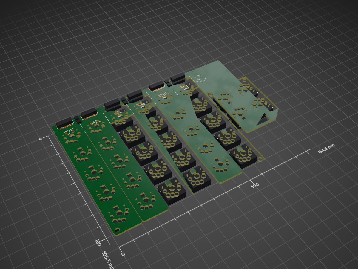
 ReSummit/Seismos18
A split keyboard that evolves the concept of the Zebra keyboard, but fancier
Seismos 5CoreStencil is an open-source printed circuit board by ReSummit, from the ReSummit/Seismos repository on GitHub, published under the GPL-3.0 licence. It is a 2-layer board of 154.5 × 105.5 mm with 100 parts on 27 nets.
It is built around the 1N4148W, SM09B-SRSS-TB(LF)(SN) and SK6812-EC20, with the SM10B-SRSS-TB(LF)(SN) and EVQPUC02K among its other parts. Its parts include 40 diodes, 35 switches and 13 connectors. It belongs with the keyboards and input boards of this library.


An evolution of the Zebra keyboard, but can be used for everyday typing. Switch between ortholinear for macro keypads and staggered for typing on the go.
Since this design utilizes daughter boards, you can even choose to move the columns around with a different rail system from the example one provided.
Allows for an interchangeable configuration between 4 and 5 row keys per column. With both halves of the keyboard, you can have a maximum of 68 keys (+2 encoder switches).
NOTE: If you had downloaded gerber files before December 5th, 2023, redownload the files as the RGB lights were not wired correctly. Apparently KiCAD displays the back side from the top perspective... doh! This is fixed. I also fixed the power switch so that sliding it up turns on the keyboard rather than this not being congruent on both sides.
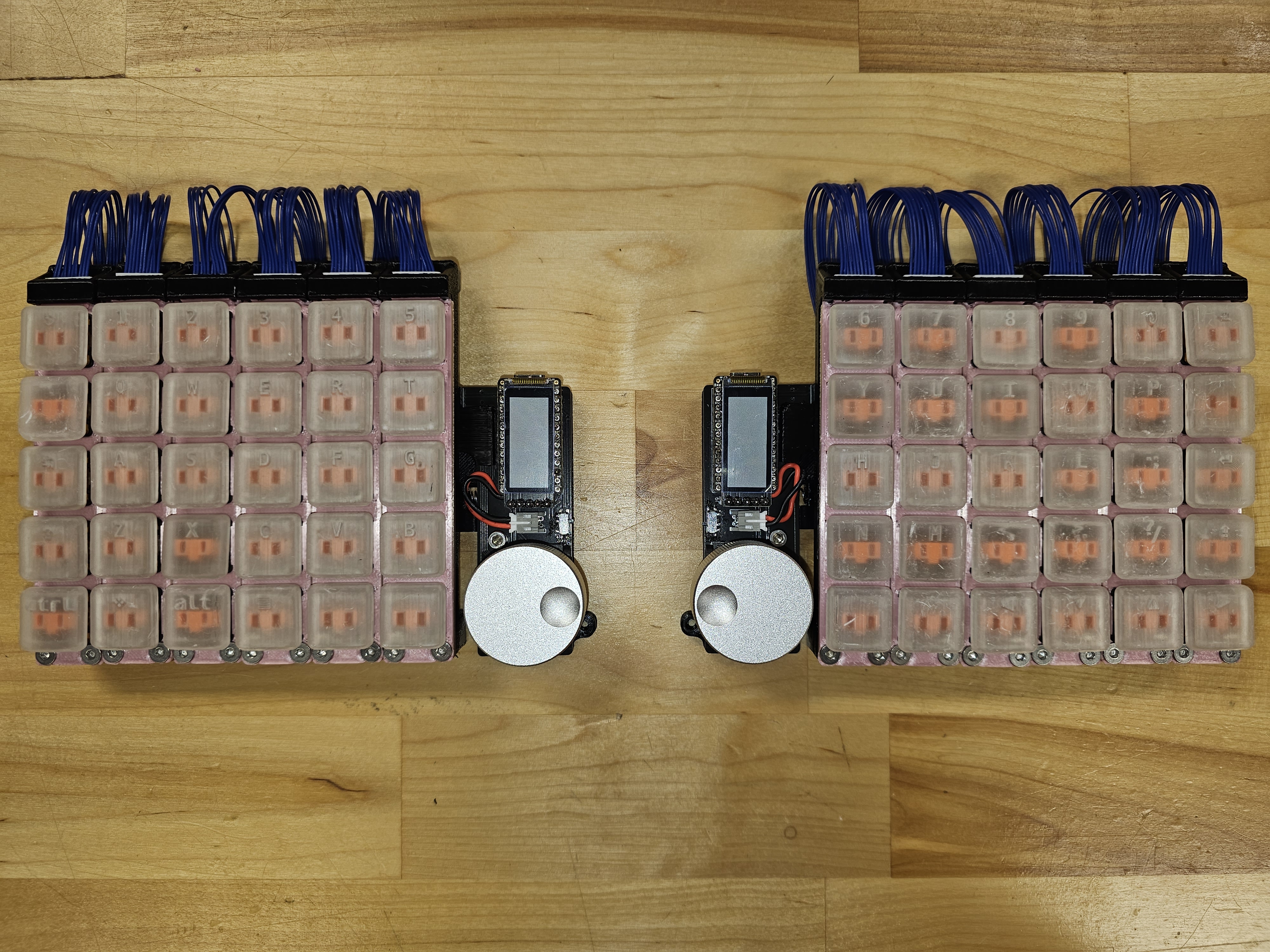
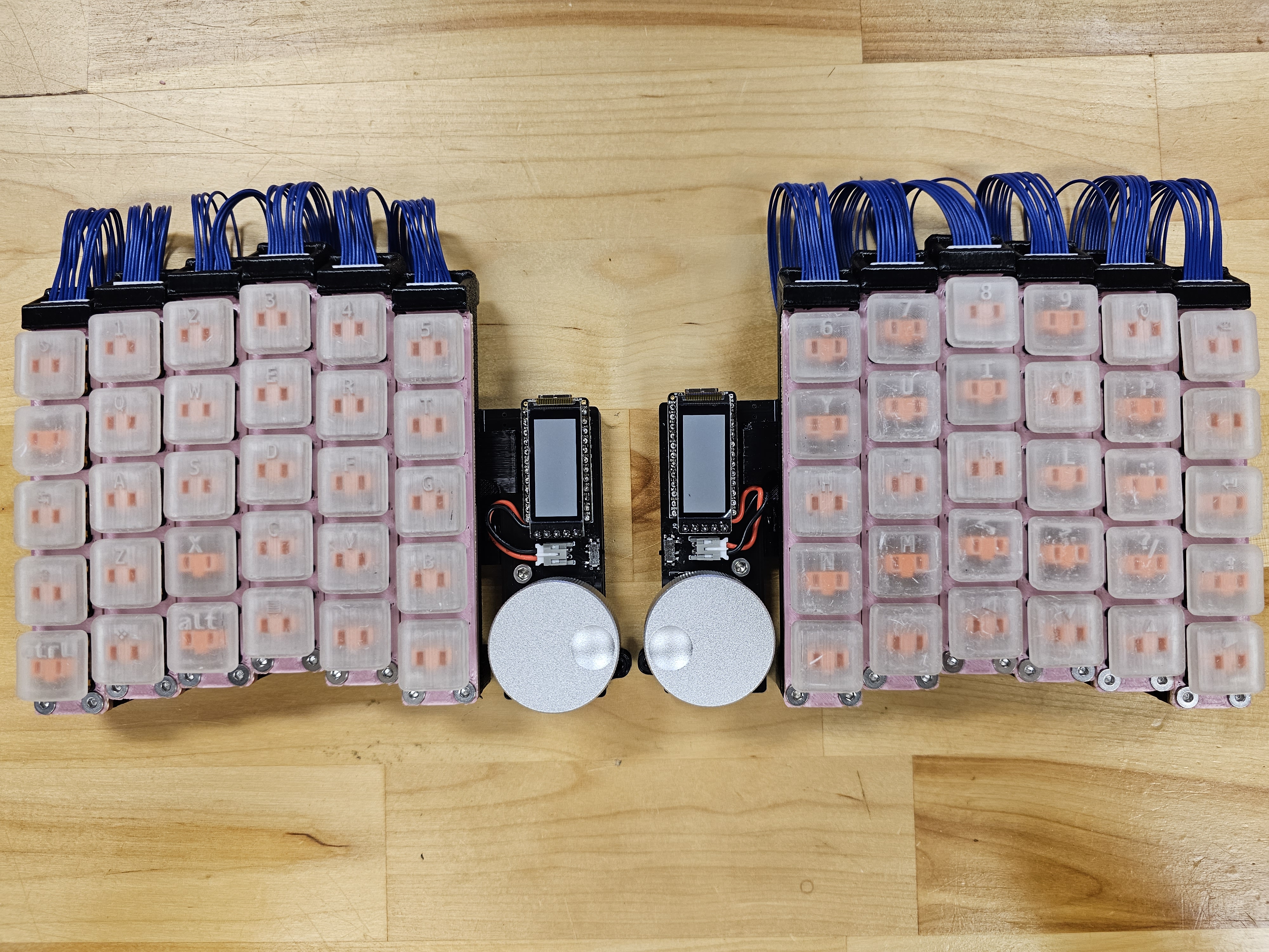
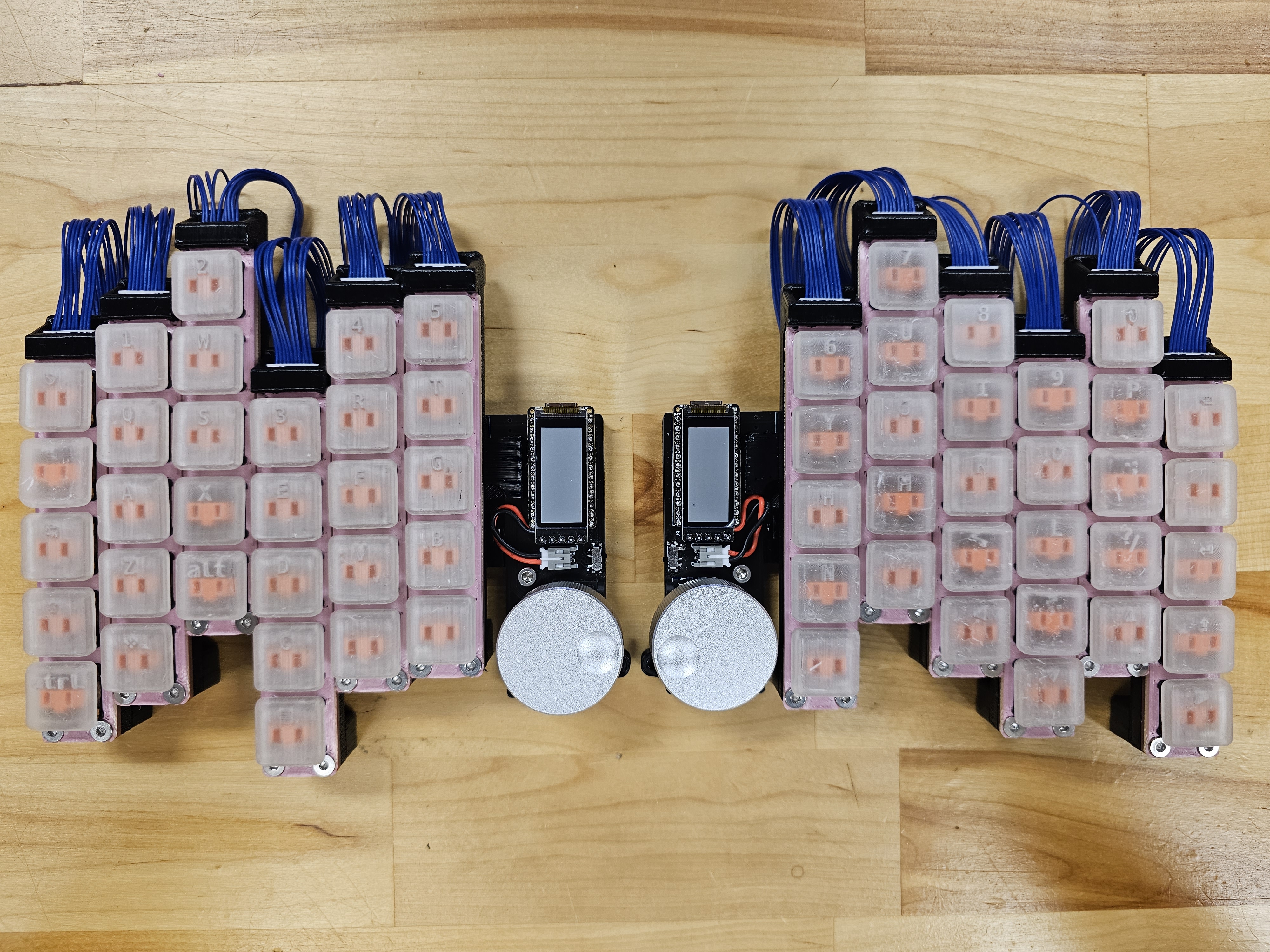
NOTE: If you check the PCB for DRC errors, most of them will come from either the keyboard_reversible.pretty footprint or the switch footprints inherited from the MiRage keyboard. Since both have been used before, they can be ignored.
All PCBs in the pcbs folder refer to the footprint and symbol libraries found in libs/Seismos-libs as well as libs/keyboard_reversible.pretty.
Wait, keyboard_reversible.pretty isn't in the git clone? You need to run git submodule initialization and update with this command:
git submodule update --init --recursiveAfter this, you should not get errors on missing libraries.
Since release v2.0.0, there are now PCBs that incorporate the 74HC595A shift register. Thanks to drFaustroll (from QMK Discord) on an example schematic for the shift register. With this shift register, displays are now on their own I2C / SPI bus and two pins are dedicated to split communications. 2 pins are now free so I have openned up these pins at the bottom of the keyboard on the front side. These ARE NOT compatible with the I2C variants of the keyboards unless you are not using the displays and will need some modification of the firmware, so choose carefully!
WARNING: If you are planning to use a display on this keyboard, note that nice!view compatibility with the I2C PCBs only applies for wireless builds only! Annoyingly, the nice!view does not use an I2C interface; it uses an SPI interface to work (whyyyyyyy). I considered moving the CS pin to the headphone jack, but this means that one of the hardware pins for I2C is not connected so this did not happen. Normal 4 pin I2C SSD1306 displays will work for wired or wireless builds however assuming that all communications happen on I2C.
There are column and thumb cluster layouts for 4 and 5 keys (however, thumb cluster can only have 4 max). This means you can get a max total of 68 keys, plus two if you are using the rotary encoders as buttons.
For this release, there are PCBs for 4 and 5 columns. Currently, the left, right, and columns are made with a maximum size of 7x5 keys per side. Something to know is that due to routing efficiency, the column order is reversed for the right side; however, row number remains the same from top to bottom.
With release v1.1.2, the PCBs are now fully tested and ready to be used. Still, read through the notes for building this keyboard a couple sections below so you know what you're getting into.
Theoretically, since JST SH connectors are pretty small, we can possibly a maximum of 12 pins, which means that you can get at most ~7 rows per column... if the microcontroller has that many pins!
Some future design thoughts:
For the JST SH cables, note that the male to male connector tips should face the same side. An example one is shown below (note it is a 9 pin JST SH cale, but should be the same for 10 pin JST cables).
Example of JST SH cable with male-to-male connectors facing the same side.

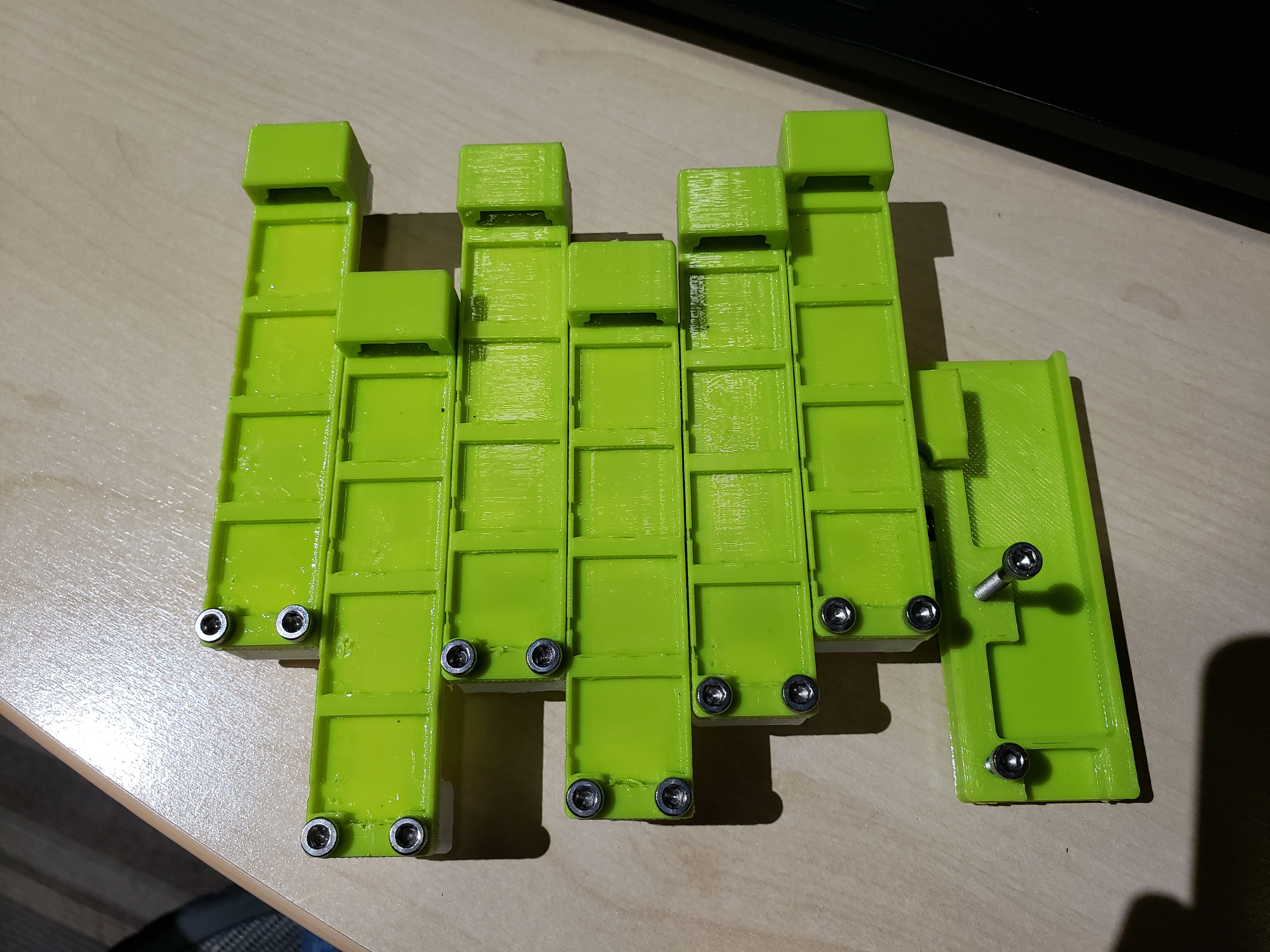
Soldering the JST SH connectors is not easy! It is recommended to use the stencil design that is provided along with the stencil jig, hot plate, and solder paste. Otherwise, use a soldering iron and rely on flux!
After you are done building the core and mantle PCBs, there are example firmware files provided. Please checkout the firmware_example folder for more details. (Unfortunately, I haven't gotten to QMK yet, so that will have to wait for a bit)
For PCBs, you will need the following:
Curious to see what it looks like? Behold, OnShape link that contains questionable features that are unlabelled... This case works with the PCBs and allows for sliding rails, but won't lock the rails. A better design is in the works, but this is a good start.
Currently, a better design is in the works to place the rails underneath the PCB instead of above; this would allow the keyboard to be more low profile. For now, this works.
This design requires the following additional parts:
Onshape Document (click on picture):
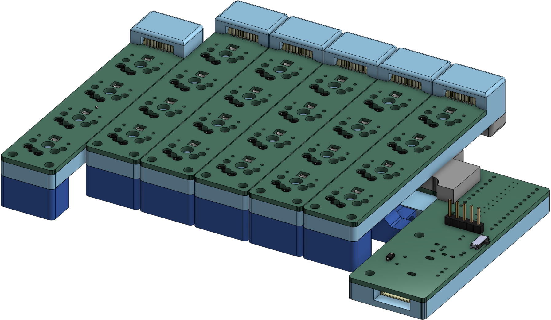
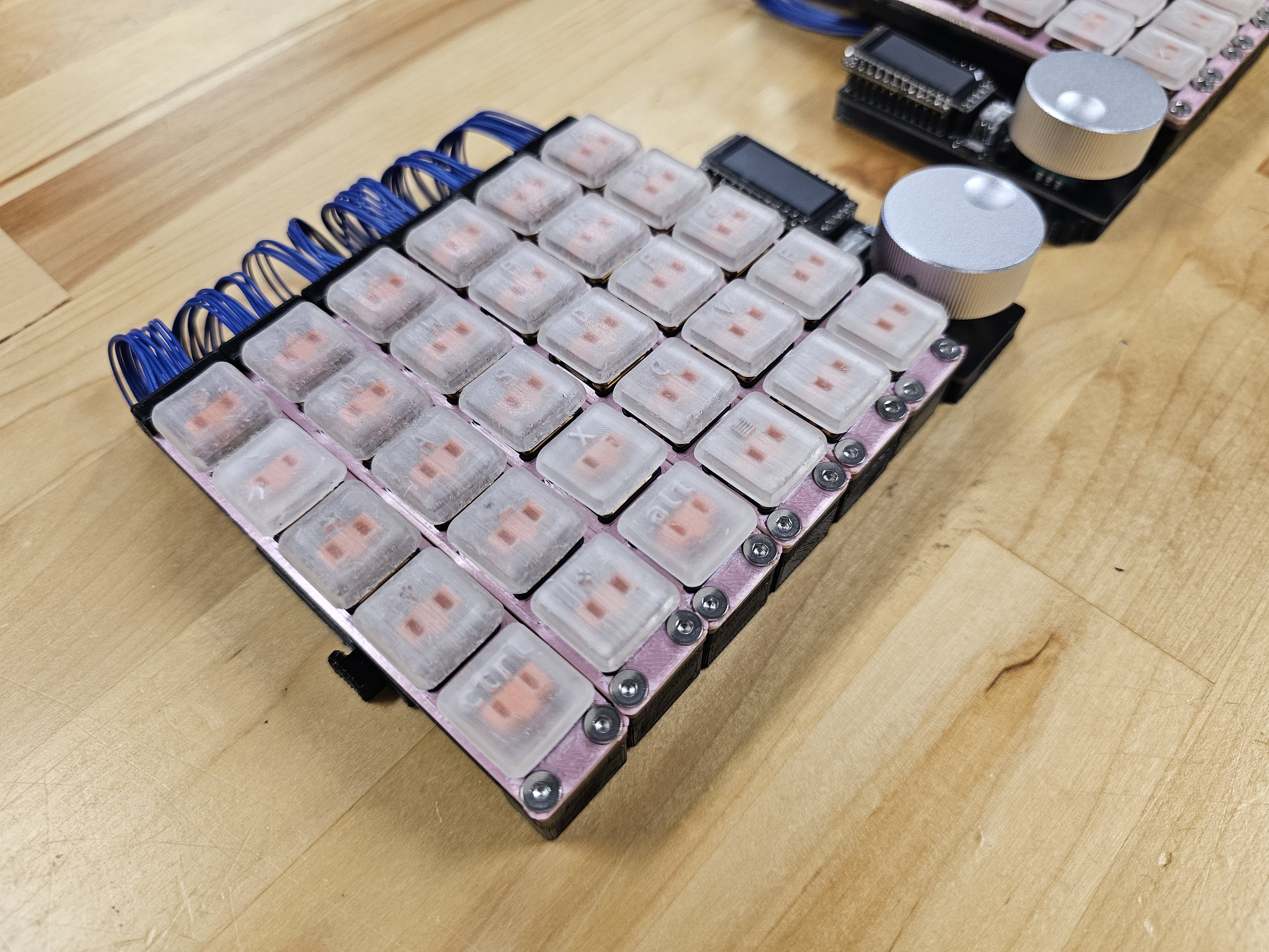
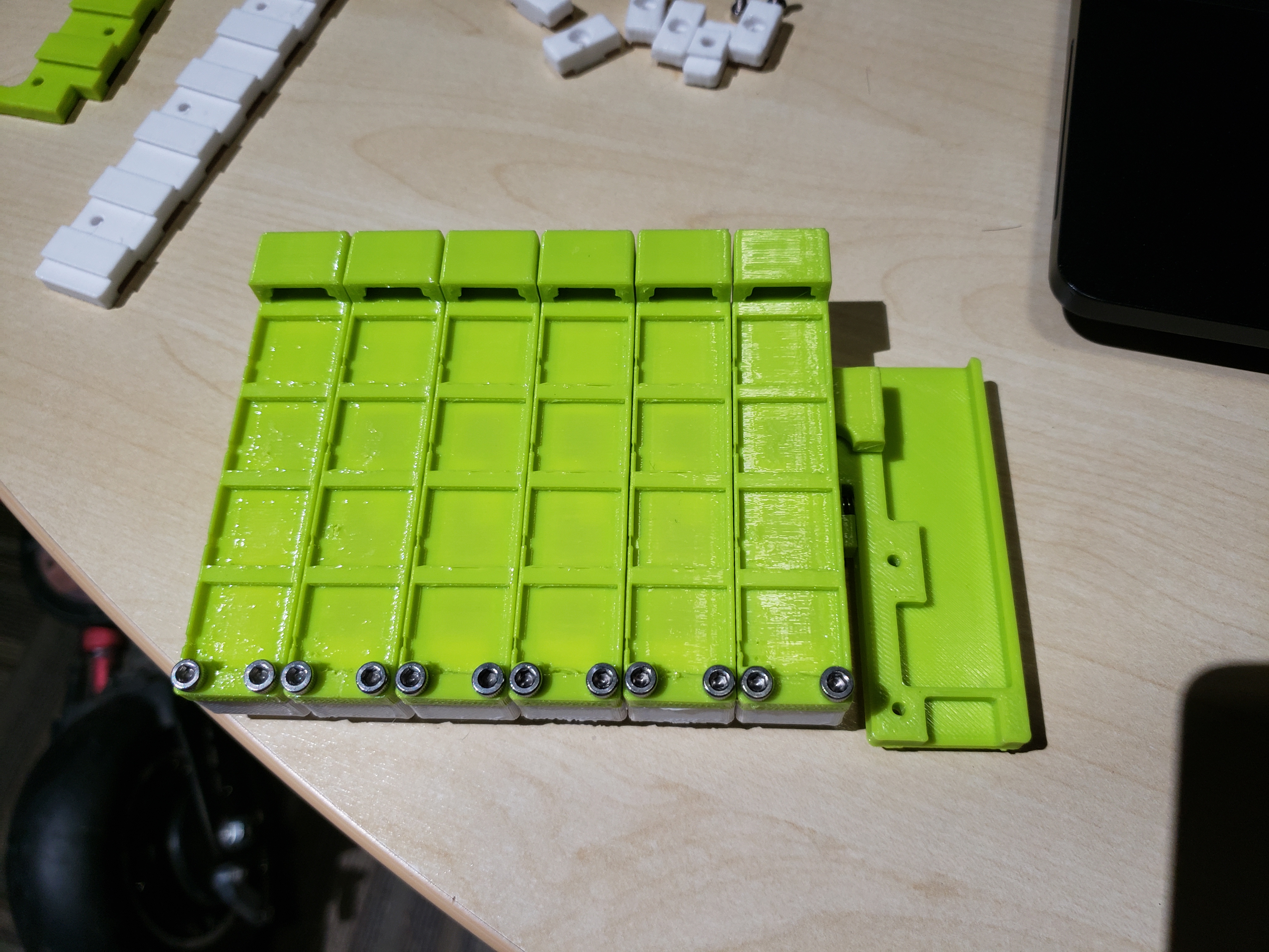
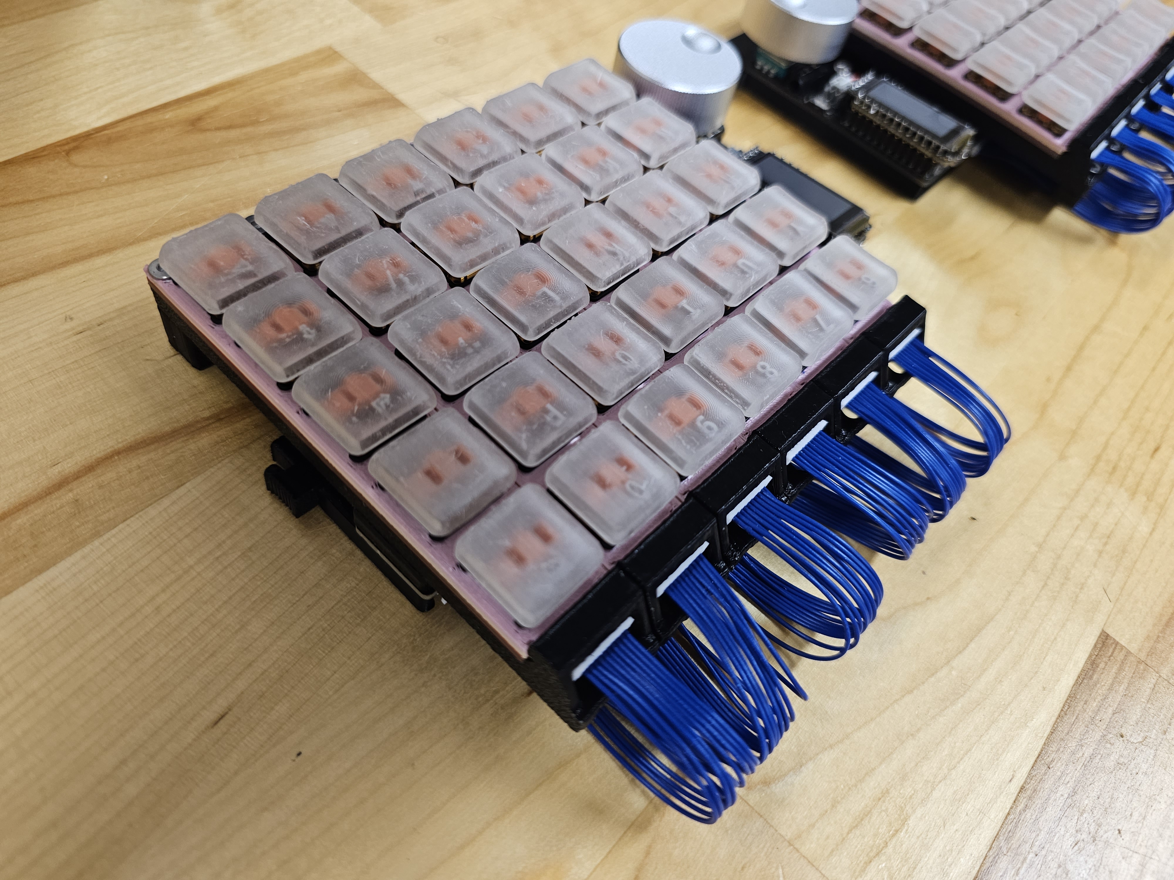 Development case design:
Seismos uses elements found from multiple places for footprints, symbols, and even the idea.
The idea for this keyboard was inspired from the Zebra keyboard. It uses jumper cables but looks to be mainly for having a physical means to determine the layout.
For footprints, they are derived from multiple places:
In the libs folder, there may be other files regarding other footprints such as the EVQPUC02K. This was found on EasyEDA on early attempts to extract the footprints. There is also the MSK-12C02 switch. This was found from mzst's blog website, which was a good reference for the switch, but I ended up using the symbol and combined with the other footprint found from EasyEDA. Archived here as well bvecause it is nice to have a backup of it.
For firmware, there are QMK, ZMK, and KMK. Only QMK has support for shift registers at the moment but I will get to the other firmwares at some point. QMK's firmware is somewhat based from the Sofle code already on the qmk_firmware, especially the oled implementation, which is untested. Also, the LICENSE may need to be updated; will check this later.
| Qty | Value | Footprint | References |
|---|---|---|---|
| 34 | 1N4148W | Diode_SMD:D_SOD-123 | D1, D1, D2, D2, D10, D11, D12, D13, D14, D15, D16, D17, D18, D19, D20, D21 +18 |
| 34 | Switch_SK6812-E_Diode | Seismos-libs:Switch_SK6812-E_Diode | SW1, SW1, SW2, SW2, SW10, SW11, SW12, SW13, SW14, SW15, SW16, SW17, SW18, SW19, SW20, SW21 +18 |
| 7 | SM09B-SRSS-TB(LF)(SN) | Seismos-libs:CONN-SMD_10P-P1.00_SM10B-SRSS-TB-LF-SN | J1, J2, J3, J4, J5, J6, J7 |
| 6 | SK6812-E | Seismos-libs:SK6812-E | LED1, LED2, LED3, LED4, LED5, LED6 |
| 6 | SM10B-SRSS-TB_(LF)(SN) | Seismos-libs:CONN-SMD_10P-P1.00_SM10B-SRSS-TB-LF-SN | J1, J8, J9, J10, J11, J12 |
| 4 | Hole_M3_3.2mm | Seismos-libs:Hole_M3_3.2mm | , 2, 4, 4 |
| 2 | , | ||
| 2 | LOGO | Seismos-libs:ReSummit_Logo | G***, G*** |
| 1 | EVQPUC02K | Seismos-libs:SW-SMD_EVQPUD02K | SW3 |
The 96 most common of 100 parts.
ReSummit/Seismos
A split keyboard that evolves the concept of the Zebra keyboard, but fancier

ReSummit/Seismos
A split keyboard that evolves the concept of the Zebra keyboard, but fancier

ReSummit/Seismos
A split keyboard that evolves the concept of the Zebra keyboard, but fancier

ReSummit/Seismos
A split keyboard that evolves the concept of the Zebra keyboard, but fancier

ReSummit/Seismos
A split keyboard that evolves the concept of the Zebra keyboard, but fancier

ReSummit/Seismos
A split keyboard that evolves the concept of the Zebra keyboard, but fancier

ReSummit/Seismos
A split keyboard that evolves the concept of the Zebra keyboard, but fancier

Ethansuttor/drone_PCB
An 80×80 mm STM32F405 flight controller for a 4S freestyle quad, running Betaflight off a custom target I wrote.


AnasSarkiz/smart-nema14-motor-controller
STEPPERONLINE 14HM11-0404S controller — unrouted work-in-progress prototype; mechanical and electrical qualification pending

HeyPCB/iris-brainstem
Iris Brainstem: power and servo hub of the Iris robot head. 9 V USB-C PD in, 6 V / 5 A servo rail in stitched copper zones (measured), 5 V rail, half-duplex servo bus with ten ports, speaker amp.

HeyPCB/iris-cortex
Iris Cortex: head controller of the Iris robot head. ESP32-S3 (16 MB flash, 8 MB PSRAM), OV2640 eye-camera FPC, iris-ring LED drivers, harness hub.

ldcyes/OpenDuck
已完成可编辑原理图、真实四层 PCB 和本地库。阶梯板面积 4510 mm²,比原 65×60 + 32×30 mm 两板总面积 4860 mm² 少 350 mm²(7.20%)。原 TDK 模块本体、四个安装孔和原 TDK 器件位置保留,回生电容采用原料号卧装,J1 因实际拔插通道冲突改为同系列 BM08 顶插。当前为工程候选,未制造,未完成热、回生瞬态、低电量或行走验收。

eggsworks/le-oeuf-v2
An ultra-low profile (Kailh PG1316S) keyboard inspired by Le Chiffre.

FugLong/OpenChord
An open-source music device for portable, expressive, and extensible audio creation.
It measures 154.5 × 105.5 mm and has 2 copper layers, 1.6 mm thick.
100 parts, built around the 1N4148W, SM09B-SRSS-TB(LF)(SN), SK6812-EC20 and SM10B-SRSS-TB(LF)(SN). The full list of its parts is on this page, with links to each part's symbol and footprint where PCBKit's library has them.
From the ReSummit/Seismos repository on GitHub, at the commit this page was made from: the board is pcbs/Core PCBs (Mantles)/Stencil/Seismos_5CoreStencil/Seismos_5CoreStencil.kicad_pcb and its schematic pcbs/Core PCBs (Mantles)/5 Key Core (Using Shift Register)/Seismos_5CoreLShift/Seismos_5CoreLShift.kicad_sch. PCBKit opens the board in the browser, with nothing to install.
Its repository publishes it under the GPL-3.0 licence: you may reuse it on that licence's terms (keep the author's notice, and for a copyleft licence share your changes alike).