4 layers80 × 80 mm
Drone PCB FC
Ethansuttor/drone_PCB
An 80×80 mm STM32F405 flight controller for a 4S freestyle quad, running Betaflight off a custom target I wrote.
83 parts

 Ethansuttor/drone_PCB
An 80×80 mm STM32F405 flight controller for a 4S freestyle quad, running Betaflight off a custom target I wrote.
Drone PCB FC is an open-source printed circuit board by Ethansuttor, from the Ethansuttor/drone_PCB repository on GitHub. It is a 4-layer board of 55 × 55 mm with 90 parts on 90 nets, routed with 553 tracks and 59 vias.
It is built around the SPA06-003, TPS5450DDAR and W25Q128JVSIQ, with the AP2112K-3.3, BMI270 and USBLC6-2SC6 among its other parts. Its parts include 29 capacitors, 22 resistors, 8 connectors, 7 ICs and 6 diodes. It belongs with the robots and motor control boards and the STM32 boards of this library.


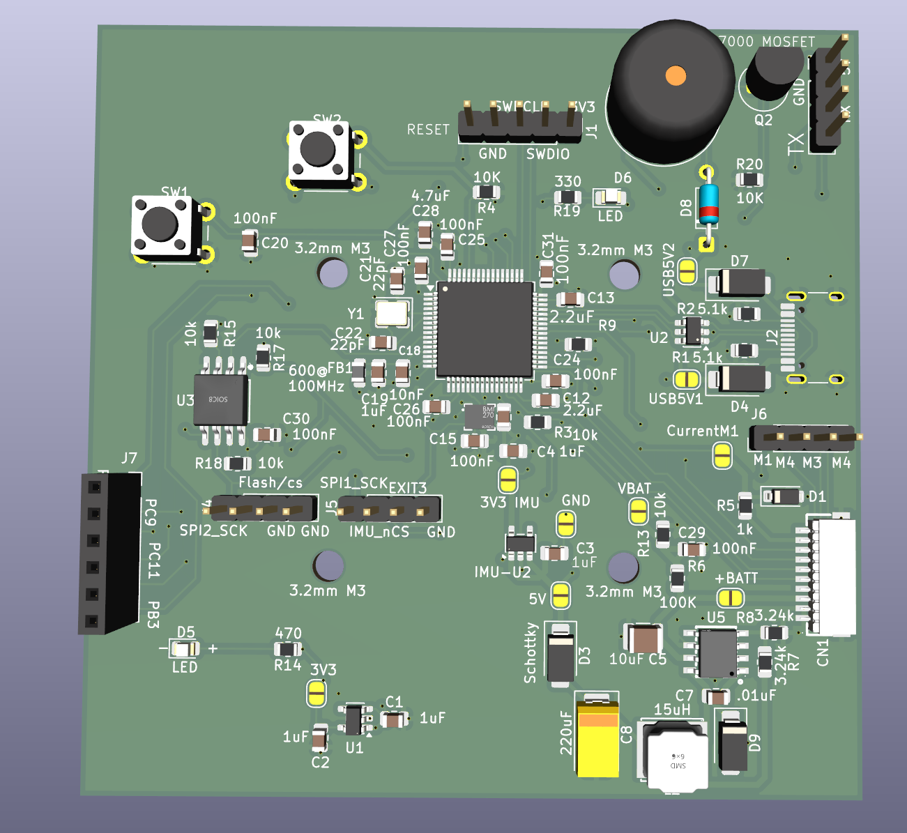
An 80×80 mm STM32F405 flight controller for a 4S freestyle quad, running Betaflight off a custom target I wrote. I built it to find out whether I could take an embedded system from a blank schematic all the way to something that actually flies.
The board is built, brought up, and running Betaflight in a printed 5-inch frame, and all four motors spin. It doesn't fly yet: it flips on every liftoff, and finding out why is the current job.
There's no VTX, camera, or OSD. Those are solved problems, and adding them would have cost layout time I wanted to spend on power architecture, IMU integration, and getting the pinout right.
The biggest constraint was self-imposed: the board has to mate with an ESC I already owned, a Flycolor Raptor BLS-04 4-in-1, using its existing 10-pin harness. That turned out to be the most useful decision I made, because the BLS-04 has no BEC. It hands you raw pack voltage and nothing else. So the board needs its own buck converter running off 16.8 V, which is a much more interesting problem than accepting a regulated 5 V from somewhere else.
The board is oversized on purpose. 80×80 mm with a standard 30.5 mm mounting pattern means it overhangs the stack, which would be silly on a real build. But everything is on the top layer in one hotplate reflow pass, and I hand-place all of it, so the extra room is worth more to me than the elegance.
The STM32F405 was the easy call — native Betaflight support, and writing the custom target is a big chunk of the point.
This is the section I'd actually want to talk about in an interview.
The IMU disappeared mid-design. I'd settled on a TDK ICM-42605. Then the entire 426xx family went reel-only at LCSC — minimum orders of a thousand-plus — and out of stock at DigiKey and Mouser. In single quantities it simply stopped existing. The replacement was a Bosch BMI270, which shares the 2.5×3.0 mm LGA-14 outline and nothing else: completely different pinout, new footprint, every IMU net re-routed, different decoupling.
What saved it was a decision I'd made months earlier for unrelated reasons. Splitting the 3.3 V rail in two — a main AP2112K for logic and a dedicated TLV733P for the gyro — meant VDD was already isolated from switching noise. When the part changed, VDD still landed on the quiet rail and VDDIO still landed on the logic rail. A forced sourcing change cost me a footprint and a re-route instead of a power redesign. I'd like to claim I planned for that. I didn't.
The tradeoff is real, though: the BMI270 ships uncalibrated, which is why Betaflight discourages it for new designs, and it caps the PID loop at 3.2 kHz instead of 8 kHz. For Acro freestyle neither matters much. It's still a downgrade I took because the alternative was not building the board.
I ordered the wrong flash chip. The BOM called for a 128 Mbit part. A 16 Mbit part arrived — 2 MB instead of 16. I found it a week after the boards shipped, while cross-checking three different BOM files against the firmware, which is a sentence that should tell you something about how I was managing the BOM.
I'm keeping it. I assumed nothing would change in firmware, since Betaflight identifies SPI NOR by JEDEC ID at runtime. That turned out to be wrong, and it cost me the most time of anything on this board. The GD25Q16E's ID (0xC84015) isn't in Betaflight 4.5.5's device table, so the chip answered every read correctly and the driver threw the reply away. Along the way I blamed the chip, then the solder joints, then the STM32's SPI peripheral. The fix was one table entry in a patch the target build applies. The lesson I took from it: don't reason about what a bus returned until you're looking at the raw bytes.
What I lose is log duration: about 22 seconds at full rate, or roughly 90 seconds if I drop the blackbox sample rate to 1/4. Since 800 Hz still resolves everything below 400 Hz, where the noise peaks that matter for filter tuning live, and since tuning runs are a minute anyway, the practical cost is that I can't log a whole pack. Every candidate chip shares the same SOIC-8 208-mil footprint, so fixing it later is a hot-air swap.
A DMA collision moved a motor output. Motor 4 originally sat on PB7, which wanted DMA1 Stream 3 — the same stream SPI2_RX uses for the blackbox flash. DShot would have fought the logger for it. The final as-built mapping is M1 = PB0 and M2 = PB1 on TIM3, M3 = PA3 and M4 = PB10 on TIM2, checked against RM0090's DMA request mapping table. I'll confirm it with dma show all at bring-up rather than trusting the table twice.
I assume I've made mistakes I haven't found yet, so the board is built to fail safely and be diagnosed.
Four normally-open solder jumpers split the power tree: buck output to the 5 V rail, 5 V to each LDO, and the quiet 3.3 V rail to the IMU. Each stage comes up on a current-limited bench supply before the next jumper is closed, so a short behind one jumper can't take the STM32 with it.
Test points sit on every rail plus multiple grounds, on the buck's switch and feedback nodes for scoping, and on both ADC sense lines for calibration. There are dedicated ground loops next to the buck and the IMU so a scope probe gets a short ground lead instead of the usual six inches of alligator clip.
Unused STM32 pins are broken out to a labelled header where the layout allowed — timer-capable pins for motor reassignment, a spare UART, spare ADC channels, and SWO. Cheap insurance against a pin-level mistake that would otherwise mean a respin.
One more thing that isn't a jumper: the schematic numbers the ESC connector in the reverse order to the manufacturer's diagram. It's only correct if the connector mates flipped. Before anything gets powered, I continuity-beep VBAT and both grounds from the mated cable to the ESC's XT60. Get that wrong and 16.8 V lands on a 3.3 V GPIO.
Boards came from JLCPCB (bare 4-layer, ENIG, frameless top-side stencil, quantity 5) and parts from LCSC. I pasted and populated one board on a hotplate and brought it up through the jumpers on 2026-08-19. Rails, USB, gyro, receiver, and both sense lines came up; the only failure was the blackbox flash, which was the firmware problem above. The two open BOM questions both closed the right way: the TPS5450 and the 15 µH inductor are what shipped.
The board is now mounted in a printed frame on the BLS-04 with EMAX 2205 motors and a 4S pack. It flips on liftoff every time.
Verify motor mapping and spin direction, set up failsafe, then log a flight with blackbox at a 1/4 sample rate and diagnose the flip from data instead of guessing on the bench.
Then I find out what else I got wrong.
| Qty | Value | Footprint | References |
|---|---|---|---|
| 13 | 100nF | Capacitor_SMD:C_0805_2012Metric | C14, C15, C20, C24, C25, C26, C27, C29, C30, C31, C32, C33, C36 |
| 8 | 10k | Resistor_SMD:R_0805_2012Metric | R3, R4, R9, R13, R15, R17, R18, R20 |
| 4 | MountingHole_3.2mm_M3 | MountingHole:MountingHole_3.2mm_M3 | 3.2mm M3, 3.2mm M3, 3.2mm M3, 3.2mm M3 |
| 3 | 1k | Resistor_SMD:R_0805_2012Metric | R5, R24, R25 |
| 3 | 1uF | Capacitor_SMD:C_0805_2012Metric | C1, C2, C19 |
| 3 | 2.2uF | Capacitor_SMD:C_0805_2012Metric | C12, C13, C35 |
| 2 | .01uF | Capacitor_SMD:C_0805_2012Metric | C11, C17 |
| 2 | 100k | Resistor_SMD:R_0805_2012Metric | R6, R23 |
| 2 | 2.2k | Resistor_SMD:R_0805_2012Metric | R12, R16 |
| 2 | 22pF | Capacitor_SMD:C_0805_2012Metric | C21, C22 |
| 2 | 4.7uF | Capacitor_SMD:C_1210_3225Metric | C6, C9 |
| 2 | 5.1k | Resistor_SMD:R_0805_2012Metric | R1, R2 |
| 2 | SS54_C22452 | drone_lib:SMA_L4.4-W2.8-LS5.4-R-RD | D2, D3 |
| 2 | SolderJumper_2_Open | Jumper:SolderJumper-2_P1.3mm_Open_RoundedPad1.0x1.5mm | JP3, JP4 |
| 1 | 0.01uF | Capacitor_SMD:C_0805_2012Metric | C10 |
| 1 | 10 | Resistor_SMD:R_0805_2012Metric | R26 |
| 1 | 10k | Resistor_SMD:R_0805_2012Metric_Pad1.20x1.40mm_HandSolder | R10 |
| 1 | 10nF | Capacitor_SMD:C_0805_2012Metric | C18 |
| 1 | 15uH | drone_lib:IND-SMD_L8.5-W8.0_PCC-M0854M | L3 |
| 1 | 1N4148W | Diode_SMD:D_SOD-123 | D8 |
| 1 | 3.24k | Resistor_SMD:R_0805_2012Metric | R11 |
| 1 | 330 | Resistor_SMD:R_0805_2012Metric | R19 |
| 1 | 330uF | Capacitor_Tantalum_SMD:CP_EIA-7343-31_Kemet-D | C16 |
| 1 | 4.7uF | Capacitor_SMD:C_0805_2012Metric | C28 |
| 1 | 470 | Resistor_SMD:R_0805_2012Metric | R14 |
| 1 | 600ohms 100MHz | Inductor_SMD:L_0805_2012Metric | FB1 |
| 1 | 8MHz | Crystal:Crystal_SMD_3225-4Pin_3.2x2.5mm | Y1 |
| 1 | AIO_5V | TestPoint:TestPoint_Pad_2.0x2.0mm | TP3 |
| 1 | AIO_GND | TestPoint:TestPoint_Pad_2.0x2.0mm | TP4 |
| 1 | AIO_VBAT | TestPoint:TestPoint_Pad_2.0x2.0mm | TP2 |
| 1 | AO3400A | Package_TO_SOT_SMD:SOT-23 | Q2 |
| 1 | AP2112K-3.3 | Package_TO_SOT_SMD:SOT-23-5 | U1 |
| 1 | BLM21PG221SN1D | Inductor_SMD:L_0805_2012Metric | FB3 |
| 1 | BMI270 | drone_lib:LGA-14_L3.0-W2.5-P0.50-BR | U7 |
| 1 | Conn_01x08 | Connector_JST:JST_SH_SM08B-SRSS-TB_1x08-1MP_P1.00mm_Horizontal | J1 |
| 1 | Current M | Jumper:SolderJumper-2_P1.3mm_Open_RoundedPad1.0x1.5mm | CurrentM1 |
| 1 | D_Zener | Diode_SMD:D_SOD-123 | D1 |
| 1 | GPS-compass | Connector_JST:JST_GH_SM06B-GHS-TB_1x06-1MP_P1.25mm_Horizontal | J4 |
| 1 | LED | LED_SMD:LED_0805_2012Metric | D5 |
| 1 | LED | LED_SMD:LED_0805_2012Metric_Pad1.15x1.40mm_HandSolder | D6 |
| 1 | MLT-8530 | drone_lib:BUZ-SMD_4P-L8.5-W8.5-P8.50-BR | BZ1 |
| 1 | Optical_flow | Connector_JST:JST_SH_SM04B-SRSS-TB_1x04-1MP_P1.00mm_Horizontal | J5 |
| 1 | Receiver | Connector_PinHeader_2.54mm:PinHeader_1x04_P2.54mm_Vertical | J3 |
| 1 | SM10B-SRSS-TB | drone_lib:CONN-SMD_10P-P1.00_SM10B-SRSS-TB-LF-SN | CN1 |
| 1 | SPA06-003 | drone_lib:LGA-8_2.0x2.5mm_P0.65mm_Baro | U8 |
| 1 | STM32F405RGTx | Package_QFP:LQFP-64_10x10mm_P0.5mm | U4 |
| 1 | SWD | Connector_PinHeader_2.54mm:PinHeader_1x05_P2.54mm_Vertical | J7 |
| 1 | Spare_I2C | Connector_JST:JST_GH_SM04B-GHS-TB_1x04-1MP_P1.25mm_Horizontal | J6 |
| 1 | TPS5450DDAR | drone_lib:ESOP-8_L4.9-W3.9-P1.27-LS6.0-TL-EP | U6 |
| 1 | TestPoint | Connector_Pin:Pin_D1.0mm_L10.0mm | TP1 |
| 1 | USART1_TX | TestPoint:TestPoint_Pad_1.5x1.5mm | TP5 |
| 1 | USBLC6-2SC6 | Package_TO_SOT_SMD:SOT-23-6 | U2 |
| 1 | USB_C_Receptacle_USB2.0_14P | Connector_USB:USB_C_Receptacle_HRO_TYPE-C-31-M-12 | J2 |
| 1 | W25Q128JVSIQ | drone_lib:SOIC-8_L5.3-W5.3-P1.27-LS8.0-BL | U3 |
Ethansuttor/drone_PCB
An 80×80 mm STM32F405 flight controller for a 4S freestyle quad, running Betaflight off a custom target I wrote.

Ethansuttor/drone_PCB
An 80×80 mm STM32F405 flight controller for a 4S freestyle quad, running Betaflight off a custom target I wrote.


ReSummit/Seismos
A split keyboard that evolves the concept of the Zebra keyboard, but fancier

Jankyneering/Waffle_hw
Hardware designs for Waffle, a compact Pager and general RF multitool.

eggsampler/12v-2x6-Current-Monitor
For more information, see the schematic or the PCB layout (KiCanvas)

ephemerkey/ephemerkey
The consumer half of the ephemerkey system, and the second PCB in this repo (alongside hardware/ephemerkey/, sharing the same scripts/kschgen.py engine, Makefile, and lib tables — the multi-project layout used by…

lalithk06/Esp32_Smart_Plug
Hardware reference design for an ESP32-S3 smart plug with mains power conversion, relay switching, RTC support, USB connectivity, and protection components.

ponrajleo/AI-Hardware-ESP32S3-
This project is part of a complete open-source hardware design course on YouTube:
It measures 55 × 55 mm and has 4 copper layers, 1.6 mm thick.
90 parts, built around the SPA06-003, TPS5450DDAR, W25Q128JVSIQ and AP2112K-3.3. The full list of its parts is on this page, with links to each part's symbol and footprint where PCBKit's library has them.
From the Ethansuttor/drone_PCB repository on GitHub, at the commit this page was made from: the board is Drone_PCB_FC_V2/Drone_PCB_FC.kicad_pcb and its schematic Drone_PCB_FC/Blackbox-flash.kicad_sch. PCBKit opens the board in the browser, with nothing to install.
Its repository states no licence, so its author keeps all rights: ask Ethansuttor before reusing the design.