

2 layers96.2 × 62.4 mm

 Paschalis/FelineWatchdog
An ESP32-based system to alert you when your cat goes missing. Monitors Wi-Fi connection between your cat's collar-mounted ESP32 device and an embedded system. Notifications sent to your iOS or Android device using ntfy and Docker. Peace of mind for cat owners.
FelineWatchdog is an open-source printed circuit board by Paschalis, from the Paschalis/FelineWatchdog repository on GitHub, published under the GPL-3.0 licence. It is a 4-layer board of 38 × 65 mm with 33 parts on 58 nets, routed with 149 tracks and 25 vias.
It is built around the ESP32-S3, AMS1117-3.3 and DW01A, with the TP4056, SS14 and FS8205A among its other parts. Its parts include 10 resistors, 5 capacitors, 5 diodes, 4 ICs and 4 connectors. It belongs with the radio and wireless boards and the ESP32 boards of this library.


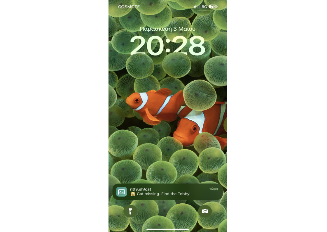
Feline Watchdog is an ESP32-based system designed to monitor the Wi-Fi connection between your cat's collar-mounted ESP32 device and your home network. If the Wi-Fi connection is lost, indicating that your cat may have wandered out of range, the system sends a notification to your iOS or Android device using the ntfy Linux tool.
Have you ever worried about your cat wandering too far from home? Feline Watchdog provides peace of mind by alerting you when your cat goes missing. By monitoring the Wi-Fi connection between your cat's collar-mounted ESP32 device and your home network, Feline Watchdog can detect when your cat is out of range and send you an alert notification on your mobile device.
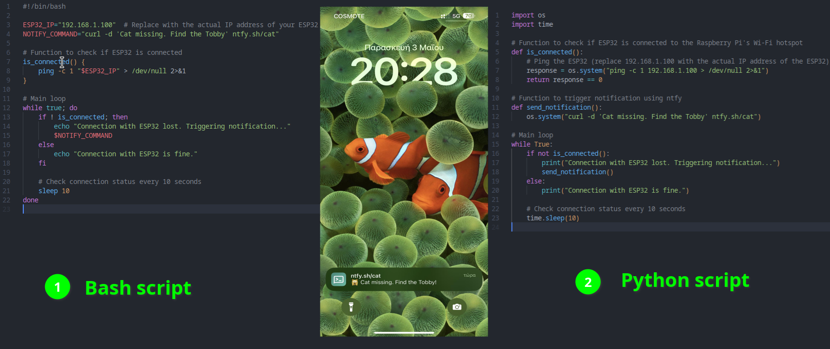
Two implementations of Embedded System Configuration
Setting Up a Wi-Fi Hotspot on Embedded System
For detailed instructions on setting up a Wi-Fi hotspot on your embedded system, please refer to the Wi-Fi Hotspot Setup Instructions.
Use the provided bash script using the nmcli tool to create a Wi-Fi hotspot on the Raspberry Pi.
bash create_hotspot.shor
./create_hotspot.shInstall Docker on your Raspberry Pi
sudo docker --version
Docker version 20.10.21, build 20.10.21-0ubuntu1~18.04.3docker run \
-v /var/cache/ntfy:/var/cache/ntfy \
-v /etc/ntfy:/etc/ntfy \
-p 80:80 \
-itd \
binwiederhier/ntfy \
serve \
--cache-file /var/cache/ntfy/cache.dbESP32 Configuration
cat.ino code to your ESP32.Raspberry Pi Monitoring and Notification
For a basic example of using NTFY with ESP boards, check out the ntfy_on_a_chip repository. It provides a foundational setup for communicating with the NTFY server and can be adapted for various projects, including this.
Connect ESP32 Directly to Router
ESP32 Configuration
cat.ino code to your ESP32.Notification Setup
This setup allows the ESP32 to be powered either by a Li-ion battery or directly from a USB source via a voltage regulator.
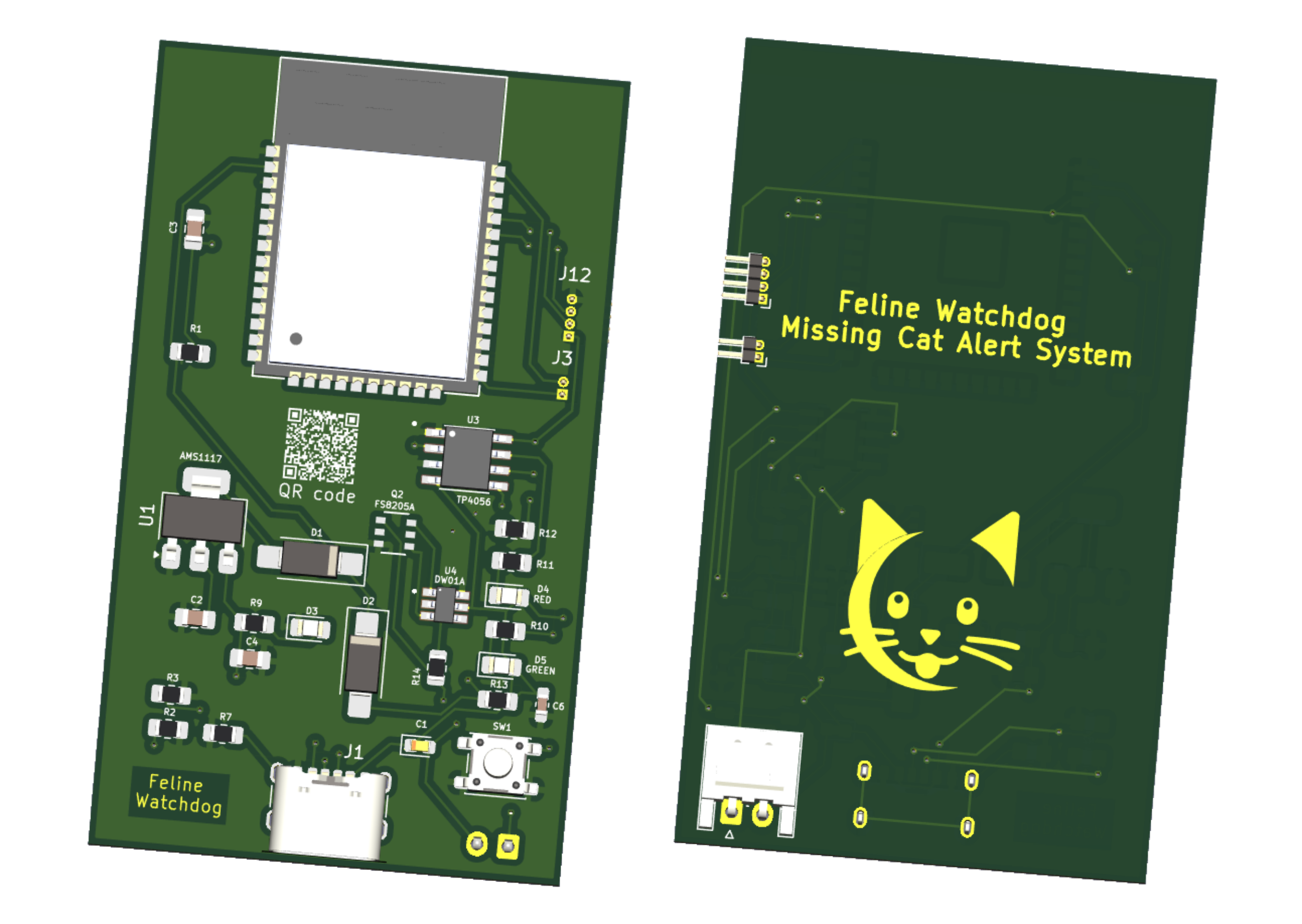
Screenshots from KiCad:
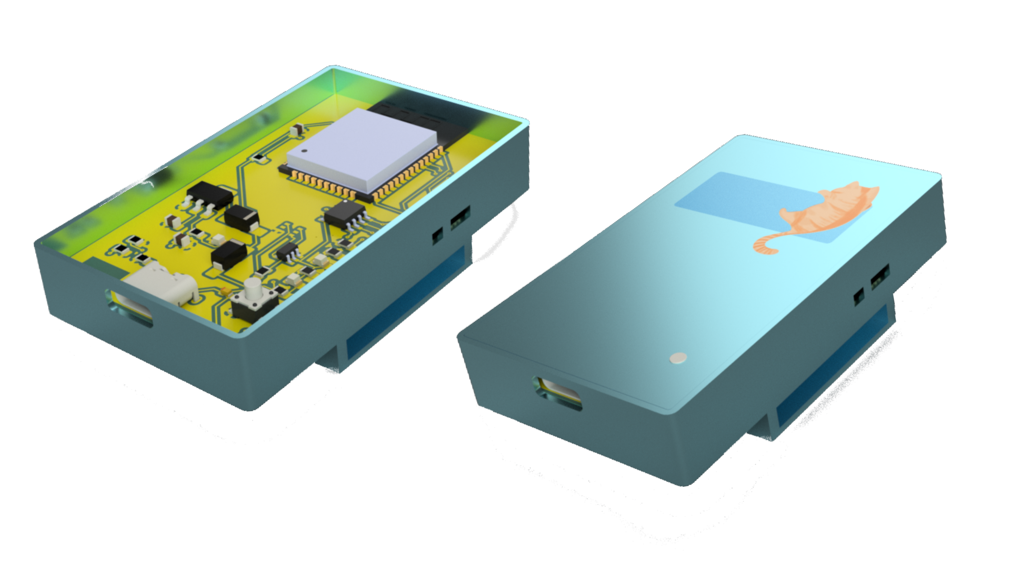
Screenshots from Fusion 360:
Screenshots from Fusion 360:
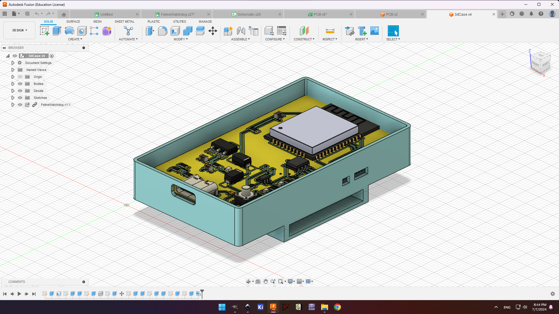
Screenshots of the printed 3D case:
Contributions are welcome! Feel free to submit pull requests or open issues if you encounter any problems.
A special thanks to the ntfy_on_a_chip repository by Gerge. The example code and documentation provided were instrumental in implementing the direct connection option for the Feline Watchdog project. The guidance on using NTFY with ESP boards and the detailed explanation of HTTPS communication enabled us to streamline our setup by connecting the ESP32 directly to a router without needing an intermediate server like a Raspberry Pi. Your work greatly facilitated our development process and contributed to the success of the Feline Watchdog system. Thank you!
We would also like to acknowledge the creators of the ntfy app. The app’s simplicity and functionality made it easy to send and receive notifications, which is a core feature of the Feline Watchdog system. The ability to integrate it seamlessly into our project greatly enhanced its effectiveness.
This project is licensed under the GPLv3 License - see the LICENSE file for details.

Thank you for visiting FelineWatchdog! ✨
| Qty | Value | Footprint | References |
|---|---|---|---|
| 3 | 10uF | Capacitor_SMD:C_0805_2012Metric_Pad1.18x1.45mm_HandSolder | C2, C3, C4 |
| 2 | 10k | Resistor_SMD:R_0805_2012Metric_Pad1.20x1.40mm_HandSolder | R1, R12 |
| 2 | 1k | Resistor_SMD:R_0805_2012Metric_Pad1.20x1.40mm_HandSolder | R10, R11 |
| 2 | 5k1 | Resistor_SMD:R_0805_2012Metric_Pad1.20x1.40mm_HandSolder | R2, R3 |
| 2 | LOGO | cat:cat | G***, G1 |
| 2 | SS14 | Diode_SMD:D_SMA_Handsoldering | D1, D2 |
| 1 | 0.1uF | Capacitor_SMD:C_0603_1608Metric_Pad1.08x0.95mm_HandSolder | C6 |
| 1 | 0.1uf | Capacitor_Tantalum_SMD:CP_EIA-1608-08_AVX-J | C1 |
| 1 | 100 | Resistor_SMD:R_0805_2012Metric_Pad1.20x1.40mm_HandSolder | R13 |
| 1 | 1M | Resistor_SMD:R_0805_2012Metric_Pad1.20x1.40mm_HandSolder | R7 |
| 1 | 1k | Resistor_SMD:R_0805_2012Metric | R14 |
| 1 | 220 | Resistor_SMD:R_0805_2012Metric_Pad1.20x1.40mm_HandSolder | R9 |
| 1 | AMS1117-3.3 | Package_TO_SOT_SMD:SOT-223-3_TabPin2 | U1 |
| 1 | Conn_01x02_Pin | Connector_PinHeader_1.00mm:PinHeader_1x02_P1.00mm_Horizontal | J3 |
| 1 | Conn_01x02_Socket | Connector_JST:JST_EH_S2B-EH_1x02_P2.50mm_Horizontal | J2 |
| 1 | Conn_01x04_Socket | Connector_PinHeader_1.00mm:PinHeader_1x04_P1.00mm_Horizontal | J12 |
| 1 | DW01A | DW01A:SOT95P280X145-6N | U4 |
| 1 | ESP-32S | ul_ESP-32S:ESP-32S_AIT | U5 |
| 1 | FS8205A | ul_FS8205A:SOT-23-6L_TCP-L | Q2 |
| 1 | GREEN | LED_SMD:LED_0805_2012Metric_Pad1.15x1.40mm_HandSolder | D5 |
| 1 | LED | LED_SMD:LED_0805_2012Metric_Pad1.15x1.40mm_HandSolder | D3 |
| 1 | LOGO | QRcat:QRcat | G2 |
| 1 | RED | LED_SMD:LED_0805_2012Metric_Pad1.15x1.40mm_HandSolder | D4 |
| 1 | RESET | VeisLibrary:MySwitch_SW_SPST_PTS647_Sx50 | SW1 |
| 1 | TP4056 | TP4056:SOP127P600X175-9N | U3 |
| 1 | USB_C_Receptacle_PowerOnly_6P | Connector_USB:USB_C_Receptacle_GCT_USB4125-xx-x-0190_6P_TopMnt_Horizontal | J1 |

ZharbolatDinmukhamed/Haptic-Glove-PCB
A wrist-mounted PCB for a haptic feedback glove, developed as part of my Research Assistantship at the Tactile Laboratory, Nazarbayev University.

MAATHES-THILAK-K/ESP32-S3_FLIGHT_CONTROLLER
A custom-designed flight controller based on the ESP32-S3 module, built for compatibility with the esp-fc firmware and Betaflight-like configuration.


BrandonFors/convention_pcb_badge
Design for a custom pcb badge for opensauce convention and maybe other conventions in the future.

yvolodym/18650-3v3-supply
KiCad: stabile 3,3-V-Versorgung aus 18650-Li-Ion-Akku – TP4056-Ladung, DW01A/FS8205A-Schutz, MT3608-Boost, AP2112K-LDO

dharahaas23/ESP32-Smart-Watch
A round, wrist-worn smart watch built around the ESP32-WROOM-32, with heart-rate sensing, a circular color display, USB-C charging, and a custom PCB antenna — designed as part of the #30DaysOfPCB progression from…

It measures 38 × 65 mm and has 4 copper layers, 1.6 mm thick.
33 parts, built around the ESP32-S3, AMS1117-3.3, DW01A and TP4056. The full list of its parts is on this page, with links to each part's symbol and footprint where PCBKit's library has them.
From the Paschalis/FelineWatchdog repository on GitHub, at the commit this page was made from: the board is Step 2: PCB Design/FelineWatchdog.kicad_pcb and its schematic Step 2: PCB Design/FelineWatchdog.kicad_sch. PCBKit opens the board in the browser, with nothing to install.
Its repository publishes it under the GPL-3.0 licence: you may reuse it on that licence's terms (keep the author's notice, and for a copyleft licence share your changes alike).