


4 layers101.6 × 76.2 mm
8051dumper
JohnDMcMaster/8051dumper
by NF6X. Forked from: https://gitlab.com/NF6X_Retrocomputing/8051dumper
41 parts27

 PainfulDiodes/BeanBoard11
QWERTY Keyboard, simple LCD display and GPIO for BeanZee
BeanBoard is an open-source printed circuit board by PainfulDiodes, from the PainfulDiodes/BeanBoard repository on GitHub, published under the MIT licence. It is a 2-layer board of 305.1 × 161.5 mm with 167 parts on 154 nets, routed with 1,056 tracks and 88 vias.
It is built around the SN74LS373N, 74LS04PC and 74LS32SC. Its parts include 64 diodes, 64 switches, 13 connectors, 9 resistors and 8 capacitors. It belongs with the lEDs and displays and keyboards and input boards of this library.
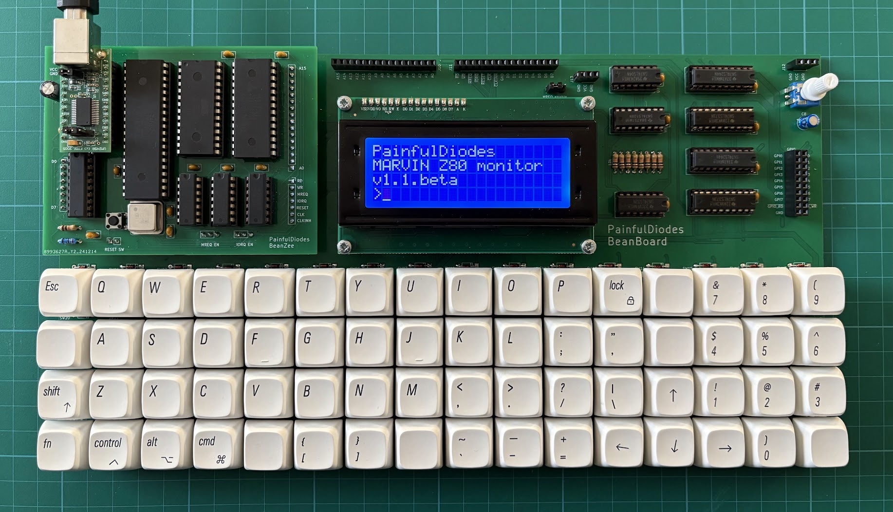
QWERTY Keyboard, simple LCD display and GPIO for BeanZee
Aiming for the simplest possible design, using a simple matrix of switches.
Diodes are used with each switch to prevent ghosting.
The circuit expects the CPU to send a "strobe" to a keyboard output port. A latch is used to capture the strobe - so that the state persists after the CPU has stopped outputting to the port. This strobe should have only one bit set high. This is the "live" row.
Then the CPU will read from a keyboard input port to sense which columns are high - columns will be activated by switches being pressed. A buffer is used to gate the columns onto the data bus.
The CPU will loop back and successively set each strobe bit high. Having gone through each bit and then read back the columns, we will have 64 bits of data (8x8) representing which keys are being pressed.
The 8 electronic rows are arranged as 4 physical rows, pairing electronic rows consecutively: 0+1, 2+3, 4+5, 6+7
The Hitachi HD44780 LCD controller has been around since the 1980's and is still popular to control character-based LCD displays:
A parallel interface makes it CPU bus friendly - with 8 data bits, enable, R/W and register select inputs.
Repeating the keyboard logic allows for 8 general purpose binary outputs and inputs which can be used for experimentation.
A 3 to 8 decoder has been used to select pairs of ports. A0 is then used to chose between ports in a pair. The BeanZee board has the logic to separate ports based on A0, and there's a similar arrangement here for LCD. The keyboard ignores A0.
KBD_PORT equ 2 ; or 3
LCD_CTRL equ 4 ; LCD control port
LCD_DATA equ 5 ; LCD data port
GPIO equ 6 ; or 7
The BeanZee Z80 bus is extended on a BeanBoard connector to allow for expansion. Note that the MREQ_enable jumper is also extended to allow the memory select logic to be changed.
| Qty | Value | Footprint | References |
|---|---|---|---|
| 64 | 1N4148 | Diode_THT:D_DO-35_SOD27_P7.62mm_Horizontal | D00, D01, D02, D03, D04, D05, D06, D07, D10, D11, D12, D13, D14, D15, D16, D17 +48 |
| 64 | SW_Push_45deg | Button_Switch_Keyboard_alt:SW_Cherry_MX_1.00u_PCB_alt | SW00, SW01, SW02, SW03, SW04, SW05, SW06, SW07, SW10, SW11, SW12, SW13, SW14, SW15, SW16, SW17 +48 |
| 8 | 10k | Resistor_THT:R_Axial_DIN0204_L3.6mm_D1.6mm_P7.62mm_Horizontal | R1, R2, R3, R4, R5, R6, R7, R8 |
| 7 | 0.1uF | Capacitor_THT:C_Disc_D5.0mm_W2.5mm_P2.50mm | C1, C2, C3, C4, C5, C6, C7 |
| 2 | 74LS244 | Package_DIP:DIP-20_W7.62mm_Socket | U3, U5 |
| 2 | Power | Connector_PinSocket_2.54mm:PinSocket_1x03_P2.54mm_Vertical | J12, J13 |
| 2 | SN74LS373 | Package_DIP:DIP-20_W7.62mm_Socket | U2, U4 |
| 1 | 100uF | Capacitor_THT:CP_Radial_D5.0mm_P2.00mm | C8 |
| 1 | 220R | Resistor_THT:R_Axial_DIN0204_L3.6mm_D1.6mm_P7.62mm_Horizontal | R9 |
| 1 | 50k | Potentiometer_THD_vertical:Pot_THD_vertical_1x03_P2.54mm | RV1 |
| 1 | 74LS04 | Package_DIP:DIP-14_W7.62mm_Socket | U7 |
| 1 | 74LS138 | Package_DIP:DIP-16_W7.62mm_Socket | U1 |
| 1 | 74LS32 | Package_DIP:DIP-14_W7.62mm_Socket | U6 |
| 1 | Address | Connector_PinSocket_2.54mm:PinSocket_1x16_P2.54mm_Vertical | J10 |
| 1 | BZ_Address | Connector_PinSocket_2.54mm:PinSocket_1x16_P2.54mm_Vertical | J1 |
| 1 | BZ_Control | Connector_PinSocket_2.54mm:PinSocket_1x07_P2.54mm_Vertical | J3 |
| 1 | BZ_Data | Connector_PinSocket_2.54mm:PinSocket_1x08_P2.54mm_Vertical | J2 |
| 1 | BZ_IORQ_enable | Connector_PinSocket_2.54mm_alt:PinSocket_1x03_P2.54mm_Vertical_alt | J5 |
| 1 | BZ_MREQ_enable | Connector_PinSocket_2.54mm_alt:PinSocket_1x03_P2.54mm_Vertical_alt | J6 |
| 1 | BZ_Power | Connector_PinSocket_2.54mm:PinSocket_1x02_P2.54mm_Vertical | J4 |
| 1 | Control/Data | Connector_PinSocket_2.54mm:PinSocket_1x16_P2.54mm_Vertical | J11 |
| 1 | GPI | Connector_PinSocket_2.54mm_alt:PinSocket_1x10_P2.54mm_Vertical_alt | J9 |
| 1 | GPO | Connector_PinSocket_2.54mm_alt:PinSocket_1x10_P2.54mm_Vertical_alt2 | J8 |
| 1 | LCD | Connector_PinSocket_2.54mm:PinSocket_1x16_P2.54mm_Vertical | J7 |
| 1 | MREQ_enable | Connector_PinSocket_2.54mm_alt:PinSocket_1x03_P2.54mm_Vertical_alt | JP1 |
JohnDMcMaster/8051dumper
by NF6X. Forked from: https://gitlab.com/NF6X_Retrocomputing/8051dumper

jes/scamp-cpu
A homebrew 16-bit CPU with a homebrew Unix-like-ish operating system.

The-Invent0r/8-bit-Computer-PCB
These are the KiCAD files for my 8-Bit Computer.


RetroStack/TRS-80-Model-I-G-E1
Hardware Replica of the TRS-80 Model I Revision G

hkzlab/CGA_Redux
The Color Graphics Adapter Redux board is a more or less faithful clone of the original IBM CGA, based on the original schematics

It measures 305.1 × 161.5 mm and has 2 copper layers, 1.6 mm thick.
167 parts, built around the SN74LS373N, 74LS04PC and 74LS32SC. The full list of its parts is on this page, with links to each part's symbol and footprint where PCBKit's library has them.
From the PainfulDiodes/BeanBoard repository on GitHub, at the commit this page was made from: the board is kicad/BeanBoard.kicad_pcb and its schematic kicad/BeanBoard.kicad_sch. PCBKit opens the board in the browser, with nothing to install.
Its repository publishes it under the MIT licence: you may reuse it on that licence's terms (keep the author's notice, and for a copyleft licence share your changes alike).