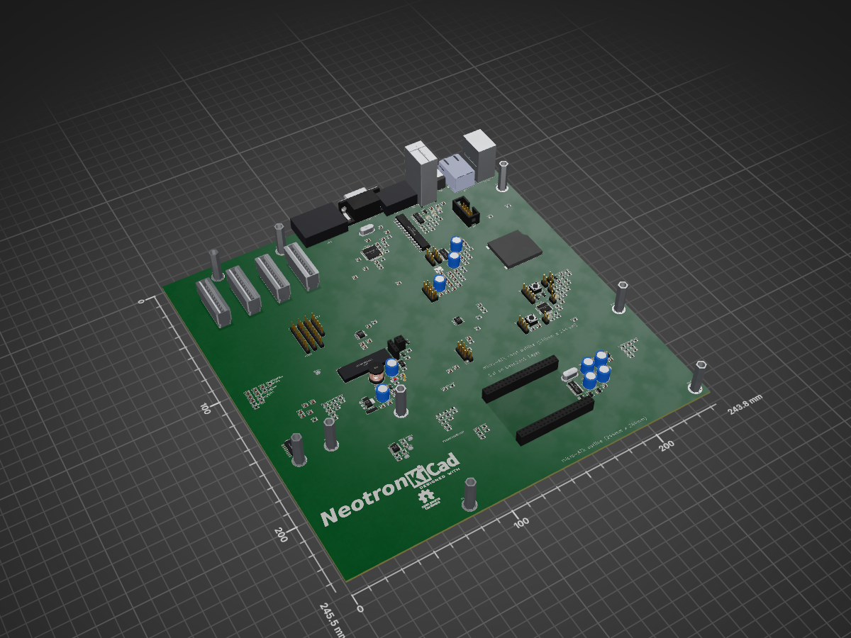
4 layers243.8 × 171.5 mm
 Neotron-Compute/Neotron-Common-Hardware4
Contains KiCad footprints and symbols shared across multiple Neotron projects.
Neotron Common Hardware is an open-source printed circuit board by Neotron-Compute, from the Neotron-Compute/Neotron-Common-Hardware repository on GitHub, published under the CC-BY-SA-4.0 licence. It is a 4-layer board of 243.8 × 245.5 mm with 287 parts on 370 nets.
It is built around the STM32F030K6T6, ST3232CDR and GSD090012SEU, with the MIC2005A-2YM5-TR, SN74AHC1G04DBVR and 74HC138 among its other parts. Its parts include 113 resistors, 73 capacitors, 26 connectors, 16 ICs and 8 diodes. It belongs with the STM32 boards of this library.


Contains KiCad footprints and symbols shared across multiple Neotron projects. It also contains example schematics for circuits we expect to see on most Neotron boards.
Power-on Reset sequencing, soft shutdown, voltage monitoring and PS/2 interfacing is handled by a separate STM32F0 SoC.
| Pin | Name | Signal | Function |
|---|---|---|---|
| 02 | PF0 | nBUTTON_PWR | Power Button Input (active low) |
| 03 | PF1 | nBUTTON_RST | Reset Button Input (active low) |
| 06 | PA0 | MON_3V3 | 3.3V rail monitor Input (1.65V nominal) |
| 07 | PA1 | MON_5V | 5.0V rail monitor Input (1.65V nominal) |
| 08 | PA2 | nSYS_RESET | Reset Output to reset the rest of the system |
| 09 | PA3 | DC_ON | PSU Enable Output |
| 10 | PA4 | SPI1_NSS | SPI Chip Select Input (active low) |
| 11 | PA5 | SPI1_SCK | SPI Clock Input |
| 12 | PA6 | SPI1_CIPO | SPI Data Output |
| 13 | PA7 | SPI1_COPI | SPI Data Input |
| 14 | PB0 | LED0 | PWM output for first Status LED |
| 15 | PB1 | LED1 | PWM output for second Status LED |
| 18 | PA8 | nHOST_IRQ | Interrupt Output to the Host (active low) |
| 19 | PA9 | USART1_TX | UART Transmit Output |
| 20 | PA10 | USART1_RX | UART Receive Input |
| 21 | PA11 | USART1_CTS | UART Clear-to-Send Output |
| 22 | PA12 | USART1_RTS | UART Ready-to-Receive Input |
| 23 | PA13 | SWDIO | SWD Progamming Data Input |
| 24 | PA14 | SWCLK | SWD Programming Clock Input |
| 25 | PA15 | PS2_CLK0 | Keyboard Clock Input |
| 26 | PB3 | PS2_CLK1 | Mouse Clock Input |
| 27 | PB4 | PS2_DAT0 | Keyboard Data Input |
| 28 | PB5 | PS2_DAT1 | Mouse Data Input |
| 29 | PB6 | I2C1_SCL | I²C Clock |
| 30 | PB7 | I2C1_SDA | I²C Data |
Note that in the above table, the UART signals labelled from the point of view of the BMC chip (i.e. UART_RX is an input to the BMC). The PS/2 signals are 5V open-collector, and so must be on 5V tolerant pins. Everything else runs at 3.3V.
This design should also be pin-compatible with the following SoCs (although the software may need recompiling with a different Peripheral Access Crate):
Note that not all STM32 pins are 5V-tolerant, and as noted above, the PS/2 pins are 5V open-collector. You must therefore ensure that whichever part you pick has 5V-tolerant pins (marked FT or FTt in the datasheet) for the PS/2 signals. All of the parts above should be OK, but they haven't been tested. Let us know if you try one!
The CPU can either be designed to solder direct to your particular motherboard design, or it can be fitted to a second PCB 'CPU card' which plugs into a socket on the motherboard. We have designed a special 80-pin socket pinout, which provides all the signals for required for the standard peripherals available in this design.
The socket is basically two 2x20 pin headers, placed 130 mil apart. This should give enough space to fit even a TQFP-176 microcontroller and some TSOP-54 SDRAM.
The pins are labelled in row.column fashion, i.e. 1.1 is top left, 1.20 is top right and 4.20 is bottom right.
 +----- Pin 1.1
 |
 v
+---------------------------------------+
|o o o o o o o o o o o o o o o o o o o o|
|o o o o o o o o o o o o o o o o o o o o|
+---------------------------------------+


+---------------------------------------+
|o o o o o o o o o o o o o o o o o o o o|
|o o o o o o o o o o o o o o o o o o o o|
+---------------------------------------+
                                       ^
                                       |
Pin 4.20 -----+| Pin | Function |
|---|---|
| 1.1 | VGA_RED5 |
| 1.2 | VGA_RED4 |
| 1.3 | VGA_RED3 |
| 1.4 | VGA_RED2 |
| 1.5 | VGA_RED1 |
| 1.6 | VGA_RED0 |
| 1.7 | VGA_GREEN5 |
| 1.8 | VGA_GREEN4 |
| 1.9 | VGA_GREEN3 |
| 1.10 | VGA_GREEN2 |
| 1.11 | VGA_GREEN1 |
| 1.12 | VGA_GREEN0 |
| 1.13 | VGA_BLUE5 |
| 1.14 | VGA_BLUE4 |
| 1.15 | VGA_BLUE3 |
| 1.16 | VGA_BLUE2 |
| 1.17 | VGA_BLUE1 |
| 1.18 | VGA_BLUE0 |
| 1.19 | VGA_HSYNC |
| 1.20 | VGA_VSYNC |
| 2.1 | VGA_DDC_SDA |
| 2.2 | VGA_DDC_SCL |
| 2.3 | UART_RX |
| 2.4 | UART_TX |
| 2.7 | 3V3 |
| 2.8 | 3V3 |
| 2.9 | 3V3 |
| 2.10 | GND |
| 2.11 | GND |
| 2.12 | GND |
| 2.13 | AUDIO_BCLK_TO_CODEC |
| 2.14 | AUDIO_DAT_TO_CODEC |
| 2.15 | AUDIO_LR_TO_CODEC |
| 2.16 | AUDIO_DAT_FROM_CODEC |
| 2.17 | AUDIO_LR_FROM_CODEC |
| 2.18 | USB_EN |
| 2.19 | USB_D- |
| 2.20 | USB_D+ |
| 3.1 | I2C_SDA |
| 3.2 | I2C_SCL |
| 3.3 | UART_CTS |
| 3.4 | UART_RTS |
| 3.7 | GND |
| 3.8 | GND |
| 3.9 | GND |
| 3.10 | 5V |
| 3.11 | 5V |
| 3.12 | 5V |
| 3.13 | ~SPI_CS7 |
| 3.14 | ~SPI_CS6 |
| 3.15 | ~SPI_CS5 |
| 3.16 | ~SPI_CS4 |
| 3.17 | ~SPI_CS3 |
| 3.18 | ~SPI_CS2 |
| 3.19 | ~SPI_CS1 |
| 3.20 | ~SPI_CS0 |
| 4.1 | ~SDMMC_CARD_DETECT |
| 4.2 | ~SDMMC_WRITE_PROT |
| 4.3 | SDMMC_DAT2 |
| 4.4 | SDMMC_DAT3 |
| 4.5 | SDMMC_CMD |
| 4.6 | SDMMC_CLK |
| 4.7 | SDMMC_DAT0 |
| 4.8 | SDMMC_DAT1 |
| 4.9 | SPI_COPI |
| 4.10 | SPI_CIPO |
| 4.11 | SPI_CLK |
| 4.12 | ~RESET |
| 4.13 | ~IRQ7 |
| 4.14 | ~IRQ6 |
| 4.15 | ~IRQ5 |
| 4.16 | ~IRQ4 |
| 4.17 | ~IRQ3 |
| 4.18 | ~IRQ2 |
| 4.19 | ~IRQ1 |
| 4.20 | ~IRQ0 |
The (up-to) seven expansion sockets allow you to add on I²C or SPI based devices at a later date. Each provides a single chip-select and a single IRQ line - the motherboard design should ensure each socket gets a unique signal for each of these. Each expansion device should also contain a AT24C256 or similar EEPROM device. To allow these EEPROM devices to be scanned, each slot also contains three EEPROM_ADDRESS pins, tied to Vcc or GND in a unique combination. These should be connected through to the EEPROM address lines on your AT24C256, thus ensuring that each expansion card has its EEPROM at a unique address - 0x50 on Slot 0 through to a maximum possible 0x57 for Slot 7. Where your board has on-board devices, you should fit an AT24C256 EEPROM for each device so that the on-board devices can be discovered, exactly as if they were on an expansion card.
The expansion slot is a simple 2x10 header. We suggest the use of a TE card-edge connector, but you could equally use two 1x10 pin-headers if desired.
The pin functions are:
     SPI_COPI   1    2   GND
     SPI_CIPO   3    4   GND
      SPI_CLK   5    6   GND
      ~SPI_CS   7    8   ~IRQ
      I2C_SDA   9   10   I2C_SCL
 EEPROM_ADDR0   11  12   EEPROM_ADDR1
 EEPROM_ADDR2   13  14   ~RESET
           5V   15  16   5V
          3V3   17  18   3V3
          GND   19  20   GND
There are symbols and footprints for the mainboard side (card-edge socket, supplies power), and the expansion card side (golden-finger edge connector, receives power).
Why not design and build your own expansion card? You could try designing:
See CHANGELOG.md for a list of detailed changes.
We recommend you have the following Git config set:
$ git config --global filter.kicad_project.clean "sed -E 's/^update=.*$/update=Date/'"
$ git config --global filter.kicad_project.smudge cat
$ git config --global filter.kicad_sch.clean "sed -E 's/#(PWR|FLG)[0-9]+/#\1?/'"
$ git config --global filter.kicad_sch.smudge cat
See https://jnavila.github.io/plotkicadsch/ for details.
This project treats a PCB like embedded firmware:
./Kicad)We do not check build outputs into this repository - ever. Instead, we run a Github Action which uses KiBot to generate our outputs. On a regular Pull Request, the build outputs are stored as artefacts against the particular Github Action run. When a new version is tagged, the build outputs are stored as files against a Github Release.
Of course, the PCB in this project isn't useful by itself - it's a starting point for your project. You should probably include this repo as a Git Submodule, and add the symbol library and footprint library to your own KiCAD project.
You can build locally using the KiBot docker container:
~/Neotron-Common-Hardware $ docker run --rm -ti -v $(pwd):/work setsoft/kicad_auto:ki7
root@12345678:/# cd /work/Kicad
root@12345678:/work/Kicad# kibot -c docs.kibot.yml -e Neotron-Common-Hardware.kicad_sch -b Neotron-Common-Hardware.kicad_pcb -d docs
This will build everything and put it in the ./Kicad/docs directory.
This schematic and PCB design is Copyright (c) The Neotron Developers.

This work is licensed under a Creative Commons Attribution-ShareAlike 4.0 International License.
Unless you explicitly state otherwise, any contribution intentionally submitted for inclusion in the work by you, as defined in the Apache-2.0 license, shall be licensed as above, without any additional terms or conditions.
| Qty | Value | Footprint | References |
|---|---|---|---|
| 27 | 10k | Resistor_SMD:R_0805_2012Metric_Pad1.20x1.40mm_HandSolder | R401, R402, R403, R404, R502, R504, R506, R1305, R1308, R1314, R1315, R1317, R1318, R1319, R1401, R1402 +11 |
| 24 | 1k | Resistor_SMD:R_0805_2012Metric_Pad1.20x1.40mm_HandSolder | R1003, R1005, R1007, R1009, R1103, R1105, R1107, R1109, R1203, R1205, R1207, R1209, R1301, R1302, R1303, R1304 +8 |
| 18 | 10u | Capacitor_SMD:C_0805_2012Metric_Pad1.18x1.45mm_HandSolder | C202, C205, C206, C207, C209, C404, C405, C502, C503, C601, C603, C604, C1301, C1302, C1304, C1401 +2 |
| 18 | 2k | Resistor_SMD:R_0805_2012Metric_Pad1.20x1.40mm_HandSolder | R203, R1001, R1002, R1004, R1006, R1008, R1101, R1102, R1104, R1106, R1108, R1201, R1202, R1204, R1206, R1208 +2 |
| 14 | 100n | Capacitor_SMD:C_0805_2012Metric_Pad1.18x1.45mm_HandSolder | C208, C701, C702, C703, C704, C705, C801, C802, C803, C804, C805, C902, C904, C906 |
| 12 | NetTie_2 | NetTie:NetTie-2_SMD_Pad0.5mm | NT301, NT302, NT303, NT304, NT305, NT306, NT307, NT308, NT309, NT310, NT311, NT312 |
| 10 | 0R | Resistor_SMD:R_0805_2012Metric_Pad1.20x1.40mm_HandSolder | R201, R202, R204, R301, R302, R303, R304, R305, R306, R501 |
| 9 | MountingHole_Pad | MountingHole:MountingHole_4.3mm_M4_Pad_Via | H101, H102, H103, H104, H105, H106, H107, H108, H109 |
| 7 | 300 | Resistor_SMD:R_0805_2012Metric_Pad1.20x1.40mm_HandSolder | R1010, R1110, R1210, R1310, R1311, R1313, R1316 |
| 7 | DNF | Capacitor_SMD:C_0805_2012Metric_Pad1.18x1.45mm_HandSolder | C301, C302, C303, C304, C305, C306, C501 |
| 6 | LED | LED_SMD:LED_0805_2012Metric_Pad1.15x1.40mm_HandSolder | D501, D502, D503, D504, D1301, D1302 |
| 5 | 100k | Resistor_SMD:R_0805_2012Metric_Pad1.20x1.40mm_HandSolder | R205, R206, R208, R209, R801 |
| 5 | 100u | Capacitor_THT:CP_Radial_D8.0mm_P5.00mm | C201, C212, C213, C401, C402 |
| 5 | 1u | Capacitor_SMD:C_0805_2012Metric_Pad1.18x1.45mm_HandSolder | C210, C211, C214, C215, C218 |
| 4 | 120u | Capacitor_THT:CP_Radial_D8.0mm_P3.50mm | C908, C909, C910, C911 |
| 4 | 12p | Capacitor_SMD:C_0805_2012Metric_Pad1.18x1.45mm_HandSolder | C809, C810, C901, C903 |
| 4 | 49R9 | Resistor_SMD:R_0805_2012Metric_Pad1.20x1.40mm_HandSolder | R804, R805, R806, R807 |
| 4 | 4k7 | Resistor_SMD:R_0805_2012Metric_Pad1.20x1.40mm_HandSolder | R207, R210, R211, R212 |
| 4 | Bridge | Jumper:SolderJumper-2_P1.3mm_Open_RoundedPad1.0x1.5mm | JP601, JP602, JP603, JP604 |
| 4 | Conn_01x02 | Connector_PinHeader_2.54mm:PinHeader_1x02_P2.54mm_Vertical | J1302, J1303, J1306, J1307 |
| 4 | MIC2005A-2YM5 | Package_TO_SOT_SMD:SOT-23-5_HandSoldering | U903, U904, U905, U906 |
| 4 | Neotron-Expansion-Slot | Neotron-Common-Hardware:Neotron-Expansion-Slot | J302, J304, J307, J308 |
| 3 | 10n | Capacitor_SMD:C_0805_2012Metric_Pad1.18x1.45mm_HandSolder | C811, C812, C1303 |
| 3 | 22u | Capacitor_SMD:C_0805_2012Metric_Pad1.18x1.45mm_HandSolder | C403, C406, C407 |
| 3 | 47p | Capacitor_SMD:C_0805_2012Metric_Pad1.18x1.45mm_HandSolder | C216, C217, C219 |
| 3 | 75 | Resistor_SMD:R_0805_2012Metric_Pad1.20x1.40mm_HandSolder | R601, R602, R603 |
| 3 | Conn_01x04 | Connector_PinHeader_2.54mm:PinHeader_1x04_P2.54mm_Vertical | J201, J203, J1304 |
| 3 | Conn_01x09 | Connector_PinHeader_2.54mm:PinHeader_1x09_P2.54mm_Vertical | J301, J303, J305 |
| 3 | DNF | Resistor_SMD:R_0805_2012Metric_Pad1.20x1.40mm_HandSolder | R604, R701, R812 |
| 2 | 10R | Resistor_SMD:R_0805_2012Metric_Pad1.20x1.40mm_HandSolder | R808, R809 |
| 2 | 180R | Resistor_SMD:R_0805_2012Metric_Pad1.20x1.40mm_HandSolder | R810, R811 |
| 2 | 1n | Capacitor_SMD:C_0805_2012Metric_Pad1.18x1.45mm_HandSolder | C806, C807 |
| 2 | 22p | Capacitor_SMD:C_0805_2012Metric_Pad1.18x1.45mm_HandSolder | C203, C204 |
| 2 | 2N7002 | Package_TO_SOT_SMD:SOT-23 | Q1302, Q1303 |
| 2 | 330R@100MHz | Inductor_SMD:L_0805_2012Metric_Pad1.15x1.40mm_HandSolder | FB201, FB202 |
| 2 | 4.7u | Capacitor_SMD:C_0805_2012Metric_Pad1.18x1.45mm_HandSolder | C905, C907 |
| 2 | SS8050 | Package_TO_SOT_SMD:SOT-23 | Q401, Q1301 |
| 2 | SW_Push | Button_Switch_THT:SW_PUSH_6mm | SW1301, SW1302 |
| 2 | ZMM5V6 | Diode_SMD:D_MiniMELF | D401, D402 |
| 1 | 12M | Crystal:Crystal_HC49-4H_Vertical | Y901 |
| 1 | 12M 20pF | Crystal:Crystal_SMD_3225-4Pin_3.2x2.5mm_HandSoldering | Y201 |
| 1 | 12k4 | Resistor_SMD:R_0805_2012Metric_Pad1.20x1.40mm_HandSolder | R802 |
| 1 | 1M | Resistor_SMD:R_0805_2012Metric_Pad1.20x1.40mm_HandSolder | R803 |
| 1 | 220n | Capacitor_SMD:C_0805_2012Metric_Pad1.18x1.45mm_HandSolder | C602 |
| 1 | 22uH | Inductor_THT:L_Radial_D9.5mm_P5.00mm_Fastron_07HVP | L401 |
| 1 | 25M | Crystal:Crystal_HC49-4H_Vertical | Y801 |
| 1 | 2k7 | Resistor_SMD:R_0805_2012Metric_Pad1.20x1.40mm_HandSolder | R906 |
| 1 | 32V 2A PTC | Neotron-Common-Hardware:Bel Fuse 0ZRS0200FF | F401 |
| 1 | 33R | Resistor_SMD:R_0805_2012Metric_Pad1.20x1.40mm_HandSolder | R1307 |
| 1 | 74AHC1G04 | Package_TO_SOT_SMD:SOT-23-5_HandSoldering | U503 |
| 1 | 74HC138 | Package_SO:SOIC-16_3.9x9.9mm_P1.27mm | U502 |
| 1 | AMS1117-3.3 | Package_TO_SOT_SMD:SOT-223-3_TabPin2 | U403 |
| 1 | AO3401A | Package_TO_SOT_SMD:SOT-23 | Q402 |
| 1 | AP2501 | Package_SO:SO-8_3.9x4.9mm_P1.27mm | U901 |
| 1 | Conn_01x04S | Connector_PinSocket_2.54mm:PinSocket_1x04_P2.54mm_Vertical | J403 |
| 1 | Conn_01x05 | Connector_PinHeader_2.54mm:PinHeader_1x05_P2.54mm_Vertical | J1305 |
| 1 | Conn_01x06 | Connector_PinHeader_2.54mm:PinHeader_1x06_P2.54mm_Vertical | J306 |
| 1 | Conn_02x02S | Connector_PinSocket_2.54mm:PinSocket_2x02_P2.54mm_Vertical | J402 |
| 1 | Conn_02x05 | Connector_PinHeader_2.54mm:PinHeader_2x05_P2.54mm_Vertical | J202 |
| 1 | Conn_02x05 | Connector_IDC:IDC-Header_2x05_P2.54mm_Vertical | J701 |
| 1 | DB9_Male_MountingHoles | Connector_Dsub:DSUB-9_Male_Horizontal_P2.77x2.84mm_EdgePinOffset7.70mm_Housed_MountingHolesOffset9.12mm | J702 |
| 1 | DC-DC Module | Neotron-Common-Hardware:K78xx-3AR3 | U401 |
| 1 | DE15HD | Neotron-Common-Hardware:Amphenol_ICD15S13E4GV00LF | J601 |
| 1 | Double-mini-DIN-6 | Neotron-Common-Hardware:Double_mini-DIN_6 | J1301 |
| 1 | ENC424J600 | Package_QFP:TQFP-44_10x10mm_P0.8mm | U801 |
| 1 | HT75xx-1-SOT89 | Package_TO_SOT_SMD:SOT-89-3 | U402 |
| 1 | Jack 2.1mm 6.3mm | Connector_BarrelJack:BarrelJack_CUI_PJ-063AH_Horizontal | J401 |
| 1 | Jumper | Connector_PinHeader_2.54mm:PinHeader_1x02_P2.54mm_Vertical | JP1301 |
| 1 | Kicad Logo | Symbol:KiCad-Logo2_12mm_SilkScreen | LOGO102 |
| 1 | MCP23S17_SP | Package_DIP:DIP-28_W7.62mm | U501 |
| 1 | Neotron Logo | Neotron-Common-Hardware:logo | LOGO101 |
| 1 | Neotron-CPU | Neotron-Common-Hardware:Neotron_CPU_Socket | U101 |
| 1 | OSHW Logo | Symbol:OSHW-Logo_11.4x12mm_SilkScreen | LOGO103 |
| 1 | PTH | TestPoint:TestPoint_THTPad_D1.5mm_Drill0.7mm | TP401 |
| 1 | RJ45 MagJack | Connector_RJ:RJ45_Amphenol_RJMG1BD3B8K1ANR | J801 |
| 1 | SD_Card | Neotron-Common-Hardware:Amphenol_GSD090012SEU | J1401 |
| 1 | SS8550 | Package_TO_SOT_SMD:SOT-23 | Q403 |
| 1 | ST3232CDR | Package_SO:SO-16_5.3x10.2mm_P1.27mm | U701 |
| 1 | STM32F030K6T6 | Package_QFP:LQFP-32_7x7mm_P0.8mm | U1301 |
| 1 | STX-4335-5BGP-S1 | Neotron-Common-Hardware:STX-4335-5BGP-S1 | U202 |
The 281 most common of 287 parts.


timvideos/HDMI2USB-TOFE-Milkymist
A board which adds control interfaces and audio for Milkymist compatibility for use with TOFE-8x hosts like the Numato Opsis.


RFStateSide/RayCouplers
Open-hardware 200 W and 2 kW RF directional coupler designs by RF StateSide LLC

M4a1x/nmr-spectrometer
My master thesis at D-CHAB (ETH Zürich) - Building a 25MHz NMR spectrometer

10robert03/stm32-nrf24-usb-node
A custom STM32C011 based wireless node with nRF24L01+ integration and USB-UART interface.
It measures 243.8 × 245.5 mm and has 4 copper layers, 1.6 mm thick.
287 parts, built around the STM32F030K6T6, ST3232CDR, GSD090012SEU and MIC2005A-2YM5-TR. The full list of its parts is on this page, with links to each part's symbol and footprint where PCBKit's library has them.
From the Neotron-Compute/Neotron-Common-Hardware repository on GitHub, at the commit this page was made from: the board is Kicad/Neotron-Common-Hardware.kicad_pcb and its schematic Kicad/Neotron-Common-Hardware.kicad_sch. PCBKit opens the board in the browser, with nothing to install.
Its repository publishes it under the CC-BY-SA-4.0 licence: you may reuse it on that licence's terms (keep the author's notice, and for a copyleft licence share your changes alike).