
2 layers224 × 224 mm
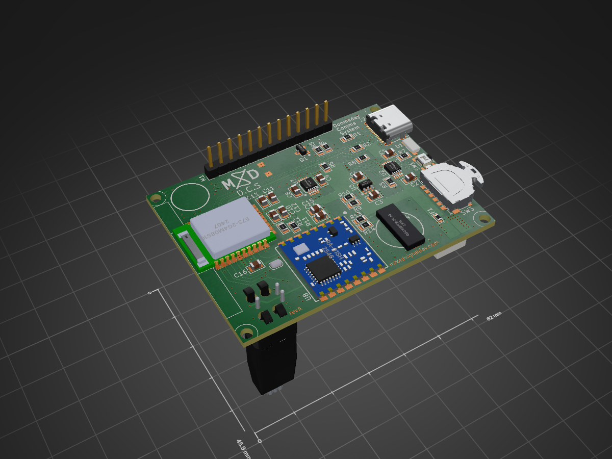
Editable source design for the Doomsday Comms System (D.C.S., SKU OS2601), board rev B.
Dcs is an open-source printed circuit board by MixedSignalDevelopment, from the MixedSignalDevelopment/K2601-Doomsday-Comms-System repository on GitHub, published under the MIT licence. It is a 4-layer board of 62 × 45.9 mm with 50 parts on 67 nets, routed with 494 tracks and 244 vias.
It is built around the E73-2G4M08S1C, RA-01SH and DRV2605LDGS, with the GSC1031YB-3V4000, MCP73833 and TLV75533DRV among its other parts. Its parts include 14 resistors, 13 capacitors, 6 ICs, 2 connectors and 2 switches.


Editable source design for the Doomsday Comms System (D.C.S., SKU OS2601), board rev B.
| File / folder | Description |
|---|---|
dcs.kicad_pro | KiCad project file — open this one |
dcs.kicad_sch | Schematic |
dcs.kicad_pcb | PCB layout (4-layer) |
fp-lib-table | Footprint-library table (project-relative, points at Misc.pretty) |
Misc.pretty/ | Bundled custom footprint library (GSC1031YB) |
3D/ | Bundled component 3D models referenced by the PCB |
Open dcs.kicad_pro in KiCad, then open the schematic and PCB editors from
the project window.
This project has no dependency on any machine-specific library path. It opens complete on a fresh KiCad install:
dcs.kicad_pcb (every placed footprint
carries its full pad/graphics definition), so the layout opens, edits, and
fabricates without any library at all.dcs.kicad_sch, so the schematic opens standalone
too.GSC1031YB) is bundled
in Misc.pretty/, and fp-lib-table references it with the project-relative
${KIPRJMOD}/Misc.pretty — so you can also place that part into new layouts.3D/; the PCB references them with
the project-relative ${KIPRJMOD}/3D/…, so the 3D viewer resolves them with no
setup. (For a single complete model of the assembled board, the STEP in
../04_3D_Model/ is also provided.)All original absolute local paths were removed — nothing points outside this
folder. The .kicad_prl (per-user GUI state) and editor history were not
included.
nRF52840 module (Ebyte E73-2G4M08S1C) · SX1262 LoRa (Ai-Thinker Ra-01SH) · ST7565 128×64 LCD (GMG12864-06D) · DRV2605L LRA haptics · MCP73833 LiPo charger · TLV75533 LDO · TM-1011A jog wheel.
| Qty | Value | Footprint | References |
|---|---|---|---|
| 5 | 100nF | Capacitors:C_0805 | C9, C10, C13, C14, C16 |
| 5 | 4.7k | Resistors:R_0805 | R6, R7, R8, R11, R12 |
| 4 | 4.7uf | Capacitors:C_0805 | C1, C2, C3, C4 |
| 2 | 100R | Resistors:R_0805 | R13, R14 |
| 2 | 10uF | Capacitors:C_0805 | C12, C15 |
| 2 | 1M | Resistors:R_0805 | R9, R10 |
| 2 | 1uF | Capacitors:C_0805 | C6, C11 |
| 2 | 5.1k | Resistors:R_0805 | R1, R2 |
| 1 | 100k | Resistors:R_0805 | R5 |
| 1 | 10k | Resistors:R_0603 | TH1 |
| 1 | 12864 Display | Modules:12864DisplayModule | M1 |
| 1 | 1A | Resistors:R_0603 | F1 |
| 1 | 22R | Resistors:R_0805 | R4 |
| 1 | 2N7002 | ICs:SOT-23 | Q1 |
| 1 | 2k | Resistors:R_0805 | R3 |
| 1 | ALED | Diodes:SideLED_4x1.4mm | D1 |
| 1 | DRV2605L | ICs:MSOP-10_3x3mm_P0.5mm | U7 |
| 1 | E73-2G4M08S1C | Modules:E73-2G4M08S1C | U1 |
| 1 | GSC1031YB-3V4000 | Misc:GSC1031YB | U4 |
| 1 | LOGO | Logos and icons:Logo MSD 10mm | G*** |
| 1 | LOGO | Logos and icons:OpenHardware_MASK | G*** |
| 1 | LOGO | Logos and icons:CE | G*** |
| 1 | LOGO | Logos and icons:OpenHardware_Copper | G*** |
| 1 | LOGO | Logos and icons:RoHS | G*** |
| 1 | LOGO | Logos and icons:JLC_Logo_14mm | G*** |
| 1 | MCP73833 | ICs:MSOP-10_3x3mm_P0.5mm | U2 |
| 1 | PH2.0 | Connector_JST:JST_PH_S2B-PH-SM4-TB_1x02-1MP_P2.00mm_Horizontal | J1 |
| 1 | Push | Switches:SideSwitch | SW1 |
| 1 | Ra-01SH | Modules:Ai-Thinker-Ra-01-LoRa | U8 |
| 1 | SolderJumper_2 | Jumper:SolderJumper-2_P1.3mm_Open_RoundedPad1.0x1.5mm | JP1 |
| 1 | TC2030-IDC | Connectors:TC2030-IDC | TC1 |
| 1 | TLV75533 | ICs:SOT-23-5 | U3 |
| 1 | TM-1011A | Switches:SlideKnob | SW3 |
| 1 | USB_C_Receptacle_USB2.0_16P | Connectors:USB_C_16P_Horizontal | J2 |


EFI-Customs/Motronic-1.3-Speeduino-Compatible-Project
Collection of resources for Speeduino related items & EFI Customs products

NOAA-PMEL/ASVCO2
Open Source Repository for the Autonomous Surface Vehicle CO2 (ASVCO2) gen2 system

PhysicsUofRAUI/hooting_owl
Hold code and eventually the pcb layout for my hooting owl retrofit

VikingMotorsports/Battery-Management-System-Capstone-2026
The BMS Capstones deliverables

devkyber/PCB
AI-assisted PCB engineering for native KiCad: source evidence, scoped changes, checked previews, human review, and reproducible release packages.

techmiguel/stillpoint
Open-hardware 60 GHz radar ceiling sensor: presence & fall detection without a camera. Matter over Thread, KiCad 4-layer Ø60 mm board.
It measures 62 × 45.9 mm and has 4 copper layers, 1.6 mm thick.
50 parts, built around the E73-2G4M08S1C, RA-01SH, DRV2605LDGS and GSC1031YB-3V4000. The full list of its parts is on this page, with links to each part's symbol and footprint where PCBKit's library has them.
From the MixedSignalDevelopment/K2601-Doomsday-Comms-System repository on GitHub, at the commit this page was made from: the board is 01_KiCad_Project/dcs.kicad_pcb and its schematic 01_KiCad_Project/dcs.kicad_sch. PCBKit opens the board in the browser, with nothing to install.
Its repository publishes it under the MIT licence: you may reuse it on that licence's terms (keep the author's notice, and for a copyleft licence share your changes alike).