2 layers29.2 × 16.5 mm
Current voltage sensor
MedadRufus/MastersProject
This project does data analysis of parameters from an E bike, in order to do accurate range estimations.
11 parts2MIT
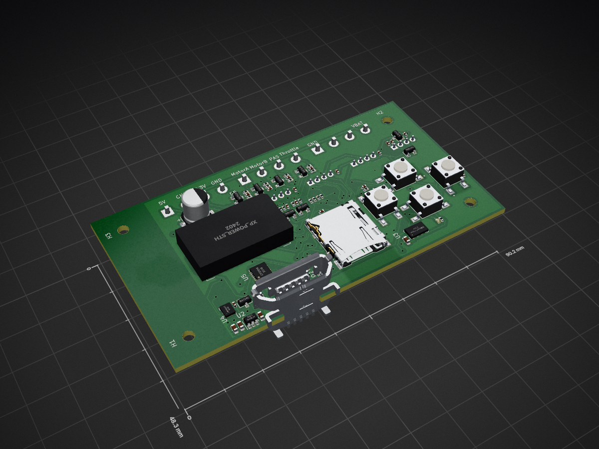
 MedadRufus/MastersProject2
This project does data analysis of parameters from an E bike, in order to do accurate range estimations.
Bike logger is an open-source printed circuit board by MedadRufus, from the MedadRufus/MastersProject repository on GitHub, published under the MIT licence. It is a 2-layer board of 90.2 × 48.3 mm with 108 parts on 47 nets, routed with 1,356 tracks and 128 vias.
It is built around the CP2104EK, ESP32-WROOM-32 and LSM6DS3, with the MS8607-02BA01, BAT54S and MMBT5551L among its other parts. Its parts include 26 capacitors, 25 resistors, 10 diodes, 9 connectors and 6 ICs. It belongs with the ESP32 boards of this library.


Design a data logger for E bikes that can record:
It needs to
The idea is to see how estimate battery discharge profiles to do accurate range and state of charge estimations.
Hardware ideas:


The following commands must be run as workarounds on the eBike Blackbox.
On the PCB, the MTDI pin, IO12, is connected to the SD card MISO pin. In order to boot up, IO12 must be held low. Otherwise, it will brownout.
Some explanation can be found on the documentation.
If driven High, flash voltage (VDD_SDIO) is 1.8V not default 3.3V. Has internal pull-down, so unconnected = Low = 3.3V. May prevent flashing and/or booting if 3.3V flash is used and this pin is pulled high, causing the flash to brownout. See the ESP32 datasheet for more details.Unfortunately, when SD card is inserted, MISO pin gets pulled up, causing continuous resets(boot loop).
So to disable this strapping function, we need to set the efuses to disable its functionality.
So we need to install esptool. On windows 10, using conda terminal, run:
pip install esptoolThen run the following command to actually set the fuses. Set the -p argument to the port your esp32 is connected to.
python -m espefuse set_flash_voltage 3.3V -p COM6You should be done now!
References:
https://www.esp32.com/viewtopic.php?t=5970
https://forum.micropython.org/viewtopic.php?t=4387#p25381
| Qty | Value | Footprint | References |
|---|---|---|---|
| 22 | TestPoint | TestPoint:TestPoint_Pad_1.0x1.0mm | TP1, TP10, TP11, TP12, TP16, TP17, TP18, TP19, TP22, TP23, TP24, TP25, TP27, TP28, TP29, TP30 +6 |
| 19 | 100nF | Capacitor_SMD:C_0402_1005Metric | C1, C2, C3, C6, C10, C13, C17, C18, C19, C20, C21, C22, C23, C24, C25, C26 +3 |
| 15 | R | Resistor_SMD:R_0402_1005Metric | R1, R2, R5, R6, R15, R16, R17, R18, R19, R20, R21, R22, R23, R24, R25 |
| 8 | 4.7k | Resistor_SMD:R_0402_1005Metric | R7, R8, R9, R10, R11, R12, R13, R14 |
| 8 | BAT54S | Package_TO_SOT_SMD:SOT-23 | D1, D2, D4, D5, D6, D7, D8, D9 |
| 4 | 1uF | Capacitor_SMD:C_0603_1608Metric | C5, C14, C15, C16 |
| 4 | Conn_01x04 | Connector:NS-Tech_Grove_1x04_P2mm_Vertical | J4, J5, J6, J7 |
| 4 | MountingHole_Pad | custom_footprints:MountingHole_2.7mm_M2.5_custom | H1, H2, H3, H4 |
| 4 | SW_Push_1571563-4 | custom_footprints:SW_1571563-4 | SW1, SW2, SW4, SW4_reset1 |
| 3 | Conn_01x04 | TerminalBlock_Phoenix:TerminalBlock_Phoenix_MKDS-1,5-4-5.08_1x04_P5.08mm_Horizontal | J2, J8, J9 |
| 2 | 10k | Resistor_SMD:R_0402_1005Metric | R3, R4 |
| 2 | 10uF | Capacitor_SMD:C_0603_1608Metric | C4, C11 |
| 2 | MMBT5551L | Package_TO_SOT_SMD:SOT-23 | Q1, Q2 |
| 1 | 10uF 100V | Capacitor_SMD:CP_Elec_6.3x7.7 | C12 |
| 1 | BAT54C | Package_TO_SOT_SMD:SOT-23 | D3 |
| 1 | CP2104 | Package_DFN_QFN:QFN-24-1EP_4x4mm_P0.5mm_EP2.6x2.6mm | U5 |
| 1 | ESP32-WROOM-32 | RF_Module:ESP32-WROOM-32 | U1 |
| 1 | LED | LED_SMD:LED_0402_1005Metric | D10 |
| 1 | LSM6DS3 | Package_LGA:LGA-14_3x2.5mm_P0.5mm_LayoutBorder3x4y | U4 |
| 1 | MS8607-02BA | Package_LGA:LGA-8_3x5mm_P1.25mm | U3 |
| 1 | Micro_SD_Card | Connector_Card:microSD_HC_Hirose_DM3AT-SF-PEJM5 | J1 |
| 1 | USB_B_Micro | Connector_USB:USB_Micro-B_Molex-105017-0001 | J3 |
| 1 | XC6210 | Package_TO_SOT_SMD:SOT-23-5 | U2 |
| 1 | XP_Power_STH | custom_footprints:STH0548S3V3 | U6 |
MedadRufus/MastersProject
This project does data analysis of parameters from an E bike, in order to do accurate range estimations.

mnemocron/FHNW-Pro4E-FS19T8-3DPrinterBoard-STM32
Marlin 2.0 compatible 3D printer board based on STM32F103 (KiCad)


SolarEnergyRacers/solar_car_control_system_v6
solarenergyracers.ch - control system (AC, DC, MC), Documents


It measures 90.2 × 48.3 mm and has 2 copper layers, 1.6 mm thick.
108 parts, built around the CP2104EK, ESP32-WROOM-32, LSM6DS3 and MS8607-02BA01. The full list of its parts is on this page, with links to each part's symbol and footprint where PCBKit's library has them.
From the MedadRufus/MastersProject repository on GitHub, at the commit this page was made from: the board is Bike_logger/pcb/pcb.kicad_pcb. PCBKit opens the board in the browser, with nothing to install.
Its repository publishes it under the MIT licence: you may reuse it on that licence's terms (keep the author's notice, and for a copyleft licence share your changes alike).