
2 layers47.5 × 56.8 mm

Nordic nRF52832 BLE development board with sensors.
Bluey is an open-source printed circuit board by electronut, from the electronut/ElectronutLabs-bluey repository on GitHub. It is a 2-layer board of 59.2 × 41 mm with 79 parts on 84 nets, routed with 1,410 tracks and 260 vias.
It is built around the CP2104EK, HDC1010EVM and AP2112K-3.3, with the LSM6DS3, DMG2307L and CR2032 among its other parts. Its parts include 24 capacitors, 17 resistors, 9 ICs, 5 connectors and 3 switches. It belongs with the radio and wireless boards and the nRF52 and nRF5x boards of this library.


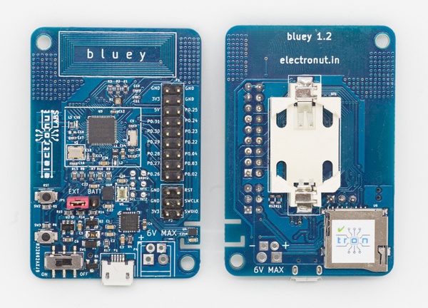
Bluey is an Open Source BLE (Bluetooth Low Energy) development board with Temperature, Humidity, Ambient Light and Accelerometer sensors.
Bluey uses the Nordic nRF52832 BLE SoC (System on a Chip) which has an ARM Cortex-M4F CPU and a 2.4 GHz radio that supports BLE and other proprietary wireless protocols. It also supports NFC, and in fact the board comes with a built-in NFC PCB antenna.
Bluey is shipped with either Arduino bootloader or Nordic DFU-OTA bootloader as per the selection at the time of purchase. While Arduino bootloader facilitates programming Bluey using Arduino IDE via serial USB cable, Nordic's DFU-OTA bootloader allows the user to update device firmware using Nordic's software development kit (SDK) and nRF Connect mobile application over bluetooth.
We have created an Arduino library with example projects to help you get started quickly.
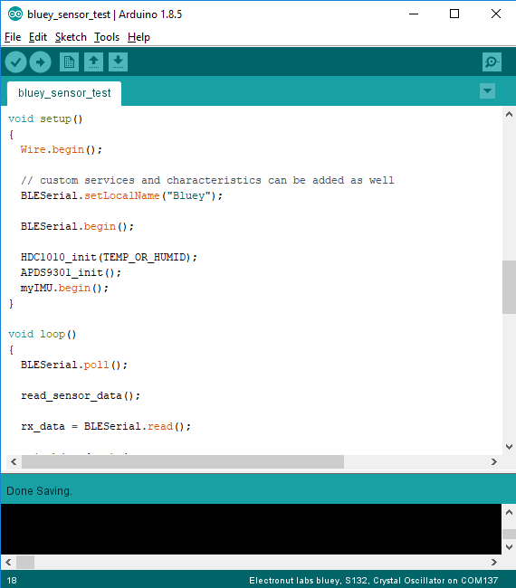
Uploading without programmer requires bootloader programmed on the board. The repo electronut/bluey_serial_dfu_bootloader
contains the source and precompiled hex file of the bootloader as hex/s132_nrf52_2.0.0_softdevice.hex.
The bootloader has the softdevice s132 in it, so no other action is needed to use the BLE Peripheral library.
Bootloader mode is triggered by pressing and holding both prss buttons on bluey and releasing the reset button. The blue LED will start blinkng at an accelerating rate repeatedly to indicate that the bootloader mode is active.
https://raw.githubusercontent.com/electronut/arduino-boards/master/package_electronutlabs_boards_index.json as an "Additional Board Manager URL"NOTE: During installation it takes the Arduino IDE a few minutes to extract the tools after they have been downloaded, please be patient.
Although Bluey is shipped with the bootloader that enables programming the device using Arduino IDE, in case you erase the bootloader from Bluey, it is possible to flash it again using a Bumpy.
load s132_nrf52_2.0.0_softdevice.hex command. Wait for the command to execute and load the file completely.detach command to free the target.Quit command to close arm-gdb debugger.After tools installation, you can now select "Electronut labs bluey" from the tools menu, and other related options.
Bluey comes preprogrammed with serial DFU bootloader, which Nordic's nrfjprog utility can program using serial connection. To trigger bootloader, press and hold button1, press the Reset button and then release button1.
Bluey's blue LED will start blinking in a 'timebomb' pattern, indicating that it is in DFU bootloader mode. Now you can press upload button in arduino IDE to program your code.
Bluey library for arduino is available at ElectronutLabs_Bluey_Arduino_Library repository. Download the zip file from github repository and extract the files to Documents/Arduino/libraries directory for Windows OS.
Set the device in bootloader mode. To trigger bootloader, press and hold button1 (SW3) , press the Reset button (RST) and then release button1.
Go to: Tools > Boards. Select Electronut labs Bluey.
Go to: Tools > Softdevice. Select S132.
Ensure Low Frequency Clock is set to Crystal Oscillator under Tools menu.
Select appropriate COM Port assigned to Bluey.
Click on Upload under Sketch menu or use Ctrl + U combination to upload code to Bluey.
Once code is upload, perform a manual reset by pressing RST button once.
                    Connector P3 on bluey

     A0       P0.02/AIN0   | 1   2 | P0.26        D0
     A1       P0.03/AIN1   | 3   4 | P0.27        D1
     A2       P0.04/AIN2   | 5   6 | P0.24/AIN4   A3
     D2            P0.22   | 7   8 | P0.29/AIN5   A4
     D3            P0.23   | 9  10 | P0.30/AIN6   A5
     D4            P0.24   | 11 12 | P0.31/AIN7   A6
     D5            P0.25   | 13 14 | Ex_vin
                     GND   | 15 16 | 3v3
                     GND   | 17 18 | GND


          button D6  - P0.16
              R  D7  - P0.19
              G  D8  - P0.18
              B  D9  - P0.17

      D10     SCL - P0.11    DRDYn - P0.12   D11
      D12     SDA - P0.13      INT - P0.14   D13
      D14    INT1 - P0.15     INT2 - P0.20   D15

              RXD - P0.08    TXD - P0.06
RTS - P0.05 CTS - P0.07PIN_LEDR, PIN_LEDG, PIN_LEDB ,LED_BUILTIN (red one), PIN_BUTTON in arduino code.Bluey has an external 32 kHz crystal connected, thus, it will be used as the source for the low frequency clock. The internal 32 kHz RC oscillator can be used by removing the external crystal. The low frequency clock is used by the delay(ms) and millis() Arduino API's.
Bluey has an additional menu item under Tools -> Low Frequency Clock that allows you to select the low frequency clock source.
arduino-BLEPeripheral library can be used creating BLE applications with bluey. Follow installation steps on it's README. See the library's API for more details on usage.
Ensure that Softdevice:"S132" is selected under tools menu. This is essential to compile BLE examples.
NOTE: Although the description says "nRF8001 or nRF51822", but nRF52832 is also supported because despite changes in CPU and peripherals, the radio interface is identical in both (API is same, but there might be changes in power/sensitivity etc.)
Once installed, you can see examples for this in examples menu. You can run most examples without modifications, unless some specify LED or button pins different from bluey's, in which case, just replace pin numbers with LED_BUILTIN, or PIN_BUTTON etc.
Use nRF connect (and other apps from nordic on play store) to scan, connect, interact with BLE peripherals created with these examples.
To get a project up and running with bluey, you need to first build the code to generate a .hex file and then upload it to the board.
If you are just getting started with the nRF52832, we recommend that you set up and use the Nordic nRF5 SDK for programming bluey. Click here to read our Getting Started with nRF5 SDK guide.
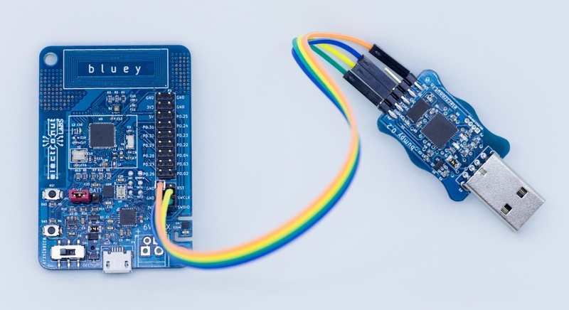
There are two main ways of uploading code into bluey:
Use the built-in OTA (over the air) bootloader which lets you upload code using a phone. Click here to read about this option.
A much more powerful option is to use an external programmer that can both upload and debug your code. Here are a few ways of doing this:
You can power bluey in several ways:
The sensors on bluey require a minimum of 2.7 Volts to function properly. Please note that the maximum power supply to bluey is 6 Volts. Do not exceed it! We also have reverse polarity protection on all power supplies, but better not to tempt fate. :-)
You can use bluey for a wide range of projects. The BLE part is ideal for IoT projects, or if you want to control something with your phone. The nRF52832 SoC has a powerful ARM Cortex-M4F CPU, so you can use this board for general purpose microcontroller projects as well.
With BLE and useful built-in sensors, bluey is a great platform for learning IoT, BLE programming, ARM, and microcontrollers in general. In fact, it's being currently used in Embedded Systems training courses.
The code folder in this repository has a bunch of interesting demo projects that we have built using bluey - so do take a look!
| Qty | Value | Footprint | References |
|---|---|---|---|
| 9 | 10K | Resistors_SMD:R_0603 | R5, R6, R9, R10, R13, R14, R15, R16, R17 |
| 6 | TEST_1P | ble-tracker:TP | DRDYn, INT, INT1, INT2, SCL, SDA |
| 5 | 0.1uF | Capacitors_SMD:C_0603 | C2, C21, C22, C23, C26 |
| 4 | 12pF | Capacitors_SMD:C_0402 | C8, C9, C16, C19 |
| 3 | 0.1uF | Capacitors_SMD:C_0402 | C7, C12, C13 |
| 3 | 1uF | Capacitors_SMD:C_0603 | C1, C3, C5 |
| 3 | 4.7K | Resistors_SMD:R_0603 | R4, R7, R8 |
| 2 | 0R | Resistors_SMD:R_0603 | R11, R12 |
| 2 | 100R | Resistors_SMD:R_0603 | R2, R3 |
| 2 | 4.7uF | Capacitors_SMD:C_0603 | C4, C14 |
| 2 | DMG2307L | TO_SOT_Packages_SMD:SOT-23 | Q1, Q2 |
| 2 | SW_PUSH | bluey:peter-switch | SW2, SW3 |
| 2 | TBD | Capacitors_SMD:C_0402 | C10, C11 |
| 1 | 0.8pF | Capacitors_SMD:C_0402 | C15 |
| 1 | 1.0uF | Capacitors_SMD:C_0603 | C20 |
| 1 | 100pF | Capacitors_SMD:C_0402 | C17 |
| 1 | 10uH | Inductors_NEOSID:Neosid_Inductor_SM0603CG | L1 |
| 1 | 15nH | bluey:L_0402 | L2 |
| 1 | 2.2uF | Capacitors_SMD:C_0603 | C6 |
| 1 | 200R | Resistors_SMD:R_0603 | R1 |
| 1 | 3.5mm ST | Terminal_Blocks:TerminalBlock_Pheonix_PT-3.5mm_2pol | P5 |
| 1 | 3.9nH | bluey:L_0402 | L3 |
| 1 | 32.768KHz | bluey:ABS07_crystal | Y1 |
| 1 | 32MHz | bluey:32MHz_crystal | Y2 |
| 1 | AP2112K | TO_SOT_Packages_SMD:SOT-23-5 | U2 |
| 1 | APDS9300-020 | bluey:APDS9301 | U5 |
| 1 | CONN_02X09 | Pin_Headers:Pin_Header_Straight_2x09_Pitch2.54mm | P3 |
| 1 | CP2104 | bluey:CP2104_QFN-24_4x4mm | U1 |
| 1 | CR2032 | bluey:BT2032 | BT1 |
| 1 | FUSE | bluey:Fuse_PTC | F1 |
| 1 | HDC1010 | bluey:HDC1010 | U4 |
| 1 | JST | bluey:JST-2-PTH | P4 |
| 1 | JTAG | Pin_Headers:Pin_Header_Straight_2x03_Pitch2.54mm | P2 |
| 1 | JUMPER3 | bluey:Pin_Header_Straight_1x03_Pitch2.54mm | JP1 |
| 1 | LOGO | bluey:electronutlabs_logo | G*** |
| 1 | LSM6DS3 | bluey:LSM6DS3 | U6 |
| 1 | Led_RGB_CA | bluey:CREE-CA | D2 |
| 1 | MBR120 | bluey:S.Diode | D1 |
| 1 | MicroSD | bluey:MicroSD_CardHolder | U9 |
| 1 | NC | Capacitors_SMD:C_0402 | C18 |
| 1 | NFC_Antenna | bluey:nfc | U7 |
| 1 | ON/OFF Switch | bluey:tactile_switch | SW1 |
| 1 | RF_Antenna | bluey:Antenna-2.45GHZ_mirror | U8 |
| 1 | USB_OTG | bluey:Micro_USB_5.9mm | P1 |
| 1 | nrf52832 | bluey:nrf52832 | U3 |
The 77 most common of 79 parts.

adilet2109/current-sensor
Bare-metal code base for current sensor board


Jonathan-0101/skeletonKey
BEng Dissertation; Penetration-testing device to highlight security system vulnerabilities


It measures 59.2 × 41 mm and has 2 copper layers, 1.6 mm thick.
79 parts, built around the CP2104EK, HDC1010EVM, AP2112K-3.3 and LSM6DS3. The full list of its parts is on this page, with links to each part's symbol and footprint where PCBKit's library has them.
From the electronut/ElectronutLabs-bluey repository on GitHub, at the commit this page was made from: the board is pcb/ver1.1/bluey.kicad_pcb. PCBKit opens the board in the browser, with nothing to install.
Its repository states no licence, so its author keeps all rights: ask electronut before reusing the design.