2 layers73.9 × 73.2 mm

 ME-IRL/SkyFax13
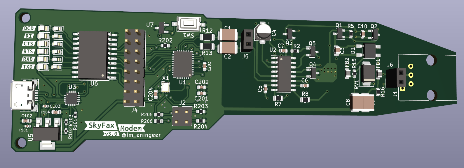
Fax and data modems built around Skyworks's ISOModem chips.
SoundCard is an open-source printed circuit board by ME-IRL, from the ME-IRL/SkyFax repository on GitHub. It is a 2-layer board of 18 × 14.2 mm with 26 parts on 18 nets, routed with 109 tracks and 6 vias.
It is built around the AD8603AUJ and TPA301D. Its parts include 9 resistors, 8 capacitors, 3 ICs, 1 diode and 1 connector.


Fax and data modems built around Skyworks's ISOModem chips.
Current functional version is 4.1 (see 3.0 below):
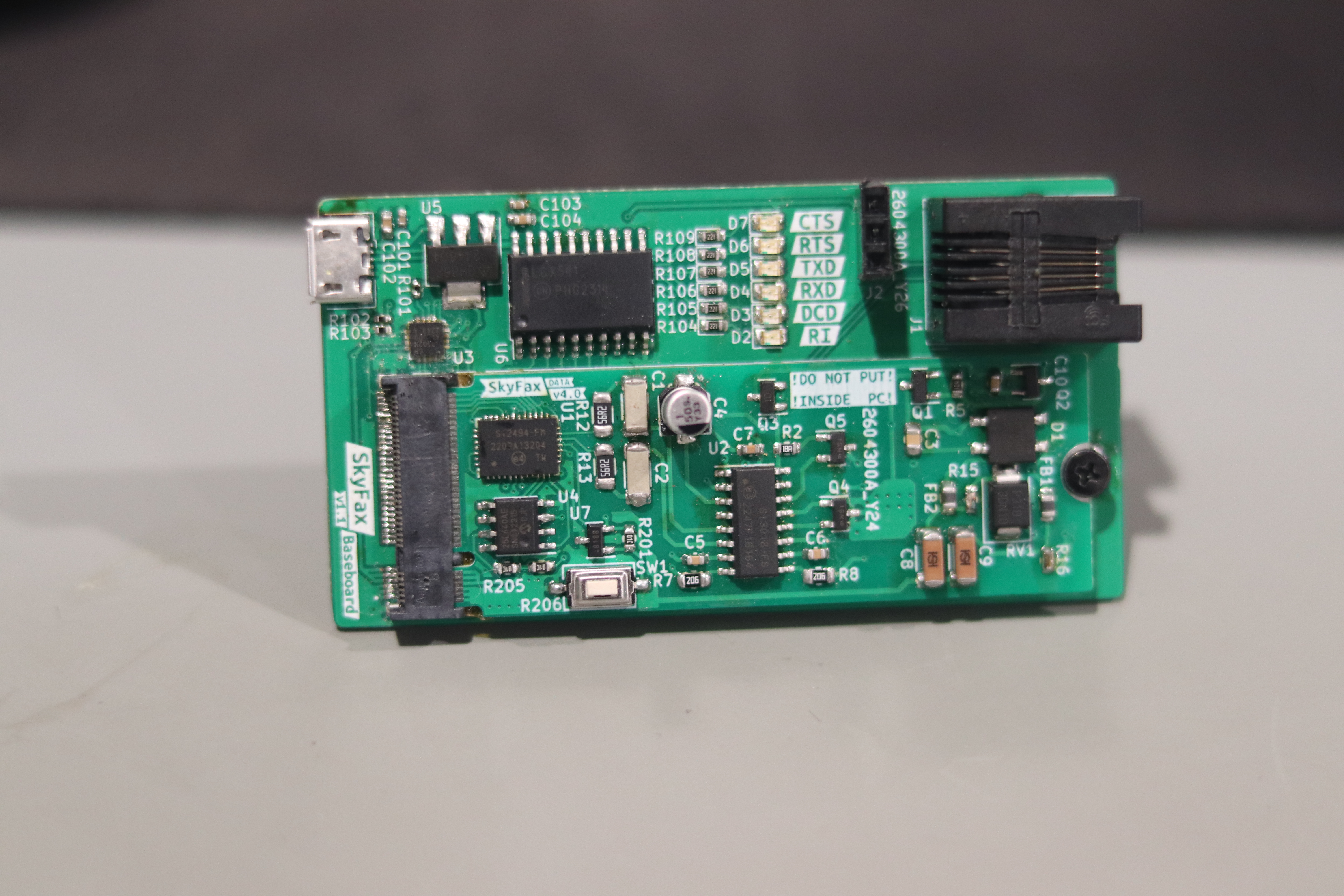
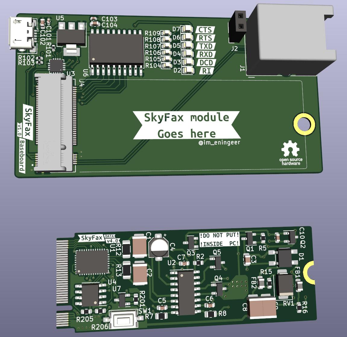
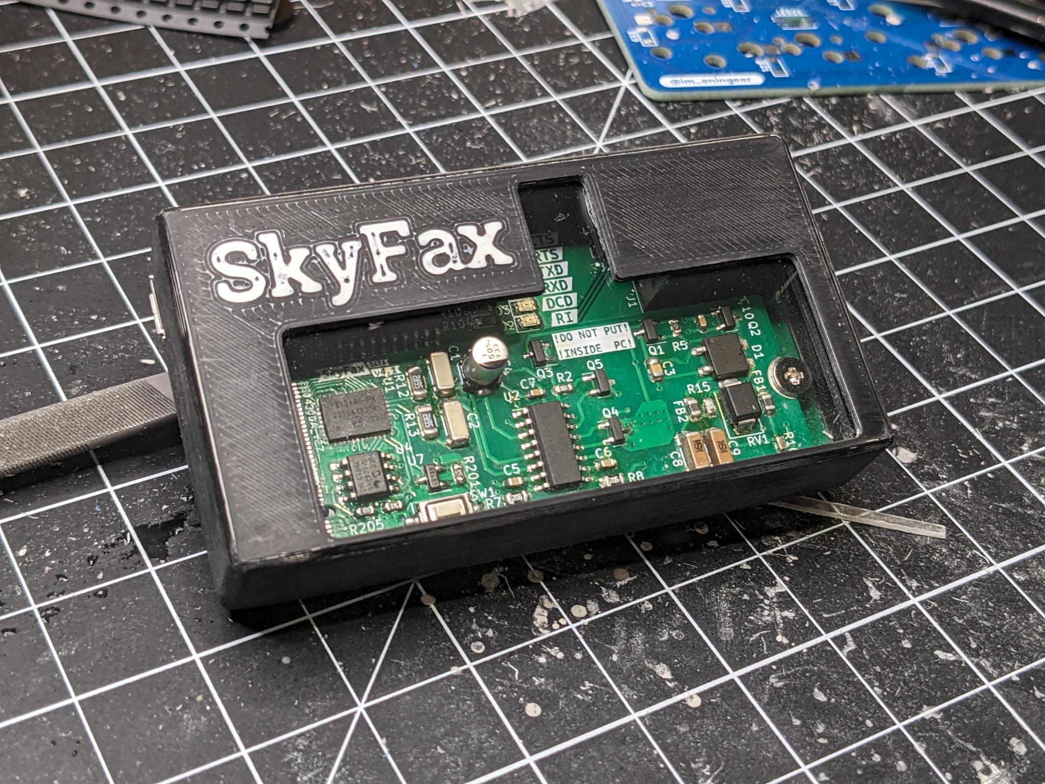
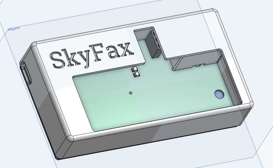
I've also designed and printed a case to go with it. The STL files can be found under /case. Or on OnShape.
Version 3.0:
If you don't have access to a working landline or a proper telephone line simulator two modems can be connected back to back directly.
There are this and this pages, but I have found this circuit to work for me:
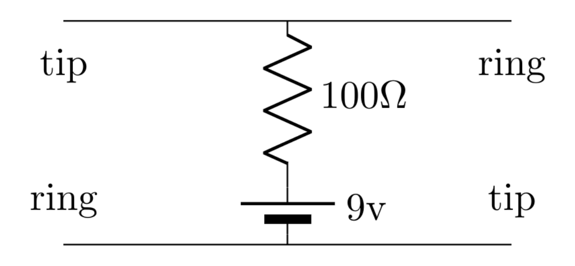
The voltage and resistance can be tweaked to provide ~20mA of current with the modem/phone off-hook.
If you'd like the schematic or just have a PCB made for the line simulator, check out the LineSim project included in this repo.
Once hooked up, you want to disable the dialtone detection with the command ATX3. Then you can just dial with ATDT on one modem and answer with ATA on the other.
See AN93 section 5.4 for details on all the AT commands supported.
| Qty | Value | Footprint | References |
|---|---|---|---|
| 5 | 0.1uF | Capacitor_SMD:C_0402_1005Metric | C1, C2, C3, C4, C6 |
| 4 | 1k | Resistor_SMD:R_0402_1005Metric | R1, R2, R3, R4 |
| 2 | 100k | Resistor_SMD:R_0402_1005Metric | R5, R6 |
| 2 | 1uF | Capacitor_SMD:C_0402_1005Metric | C5, C8 |
| 2 | 3.01k | Resistor_SMD:R_0402_1005Metric | R7, R8 |
| 2 | AD8603 | Package_TO_SOT_SMD:TSOT-23-5 | U1, U2 |
| 1 | 2.2nF | Capacitor_SMD:C_0402_1005Metric | C7 |
| 1 | 220 | Resistor_SMD:R_0402_1005Metric | R9 |
| 1 | 50k | Potentiometer_SMD:Potentiometer_Bourns_TC33X_Vertical | RV1 |
| 1 | Conn_01x03 | Connector_PinHeader_2.54mm:PinHeader_1x03_P2.54mm_Vertical | J1 |
| 1 | G*** | kibuzzard-650CC8CA | kibuzzard-650CC8CA |
| 1 | G*** | kibuzzard-650CC8A2 | kibuzzard-650CC8A2 |
| 1 | LED | LED_SMD:LED_0805_2012Metric | D1 |
| 1 | Speaker | SoundCard:PC_Speaker_15.0mm | LS1 |
| 1 | TPA301 | Package_SO:SOIC-8_3.9x4.9mm_P1.27mm | U4 |

LadyRoninEngineer/Si473x
Data Supporting development of Si473x series radios


niki100jad/POQUITO_ADCS
ADCS for a PocketQube mission (Warning: Still untested!)

scalinq-lab/cryomagsens
The sensor unit was designed in KiCad 10 and manufactured by JLCPCB. It is built in a flex PCB material to achieve a very small build height, in order to come very close to the device under test.


ZeshuLiu/SX-70-Mk2
把板子上的U+ U- GND VCC焊到usb线上,连接电脑后可以当作树莓派Pico开发板进行操作,上传代码的参见这里(树莓派官网)。 \ 在将机身主控安装至机器内部之前需要将micropython固件及代码烧录至控制器中。后续可以通过机身控制器上的USB接口连接开发板并更新python代码。 将code根目录中的所有python文件上传至控制器(文件夹不需要),并且将gmain.py命名为…


It measures 18 × 14.2 mm and has 2 copper layers, 1.29 mm thick.
26 parts, built around the AD8603AUJ and TPA301D. The full list of its parts is on this page, with links to each part's symbol and footprint where PCBKit's library has them.
From the ME-IRL/SkyFax repository on GitHub, at the commit this page was made from: the board is SoundCard/SoundCard.kicad_pcb and its schematic LineSim/LineSim.kicad_sch. PCBKit opens the board in the browser, with nothing to install.
Its repository states no licence, so its author keeps all rights: ask ME-IRL before reusing the design.
