2 layers73.9 × 73.2 mm

 ME-IRL/SkyFax13
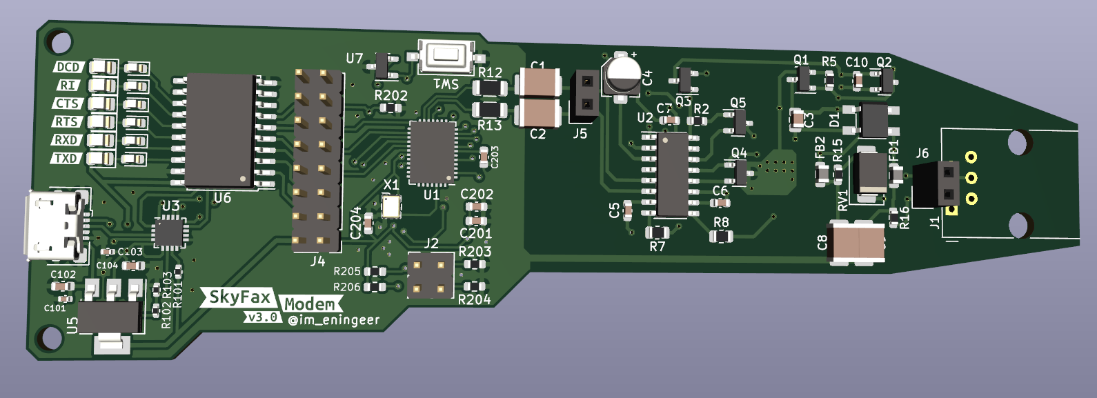
Fax and data modems built around Skyworks's ISOModem chips.
LineSim is an open-source printed circuit board by ME-IRL, from the ME-IRL/SkyFax repository on GitHub. It is a 4-layer board of 29.7 × 29 mm with 7 parts on 5 nets, routed with 22 tracks and 0 vias.
Its parts include 2 resistors, 2 connectors, 1 diode and 1 switch.
Fax and data modems built around Skyworks's ISOModem chips.
Current functional version is 4.1 (see 3.0 below):
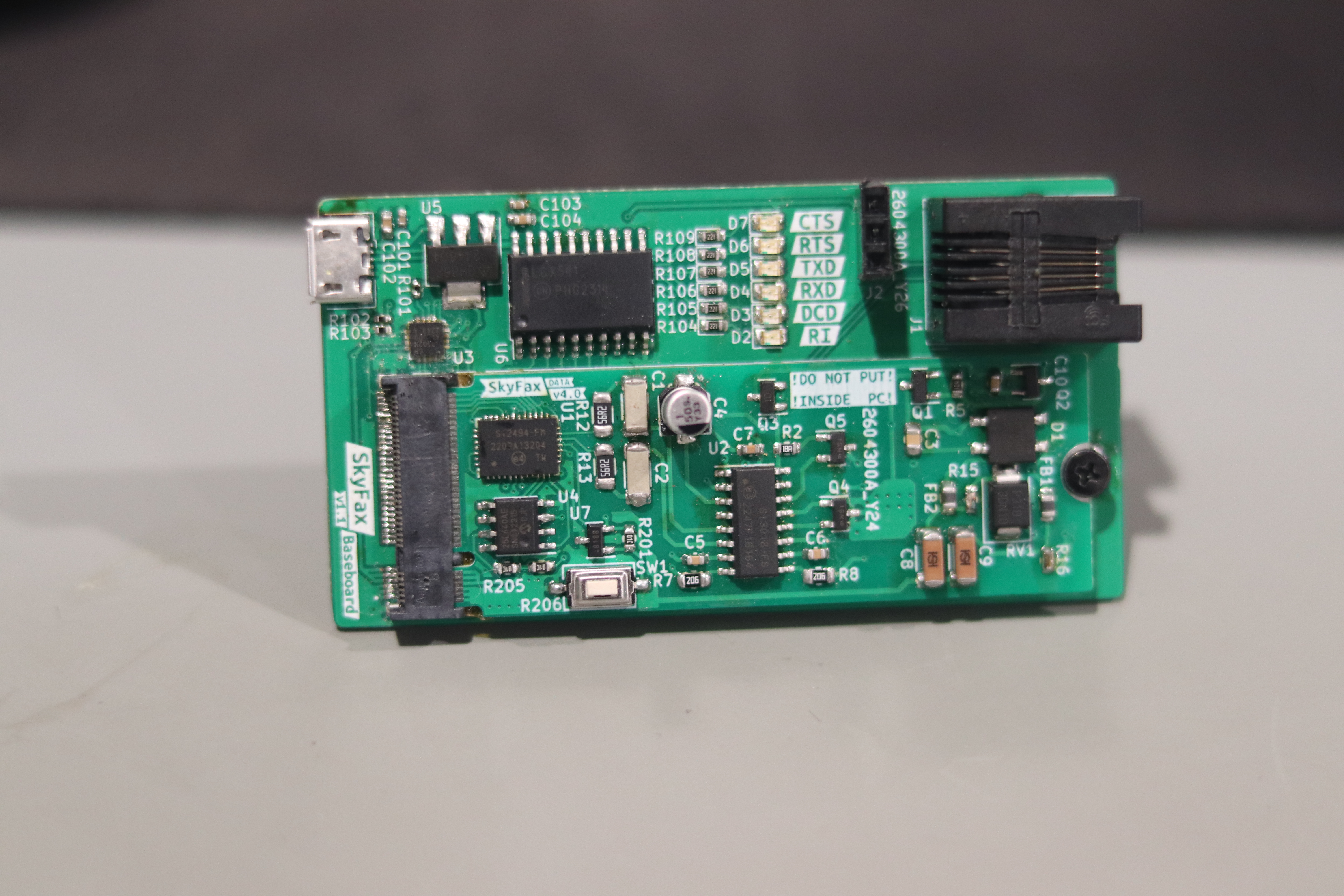
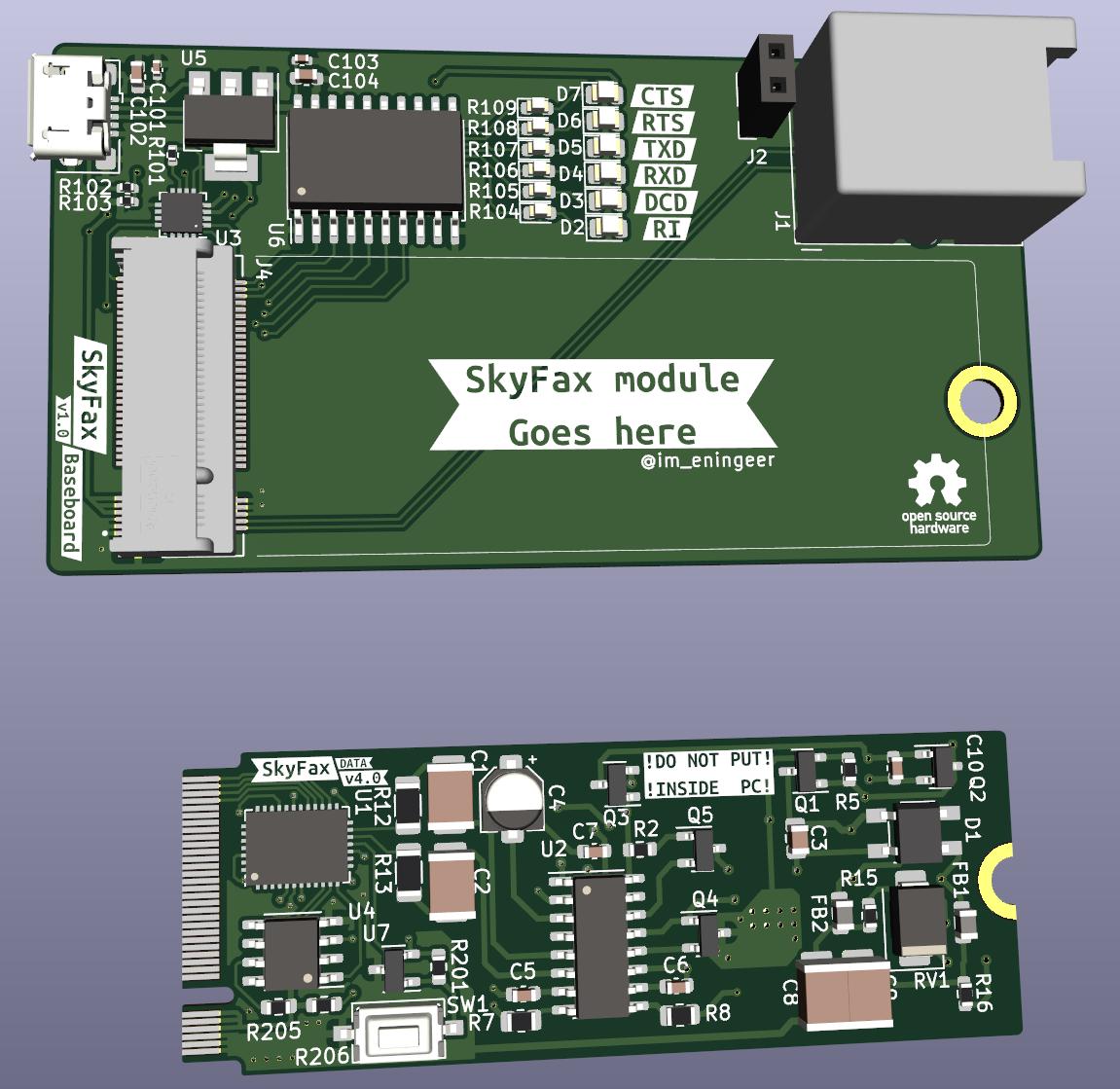
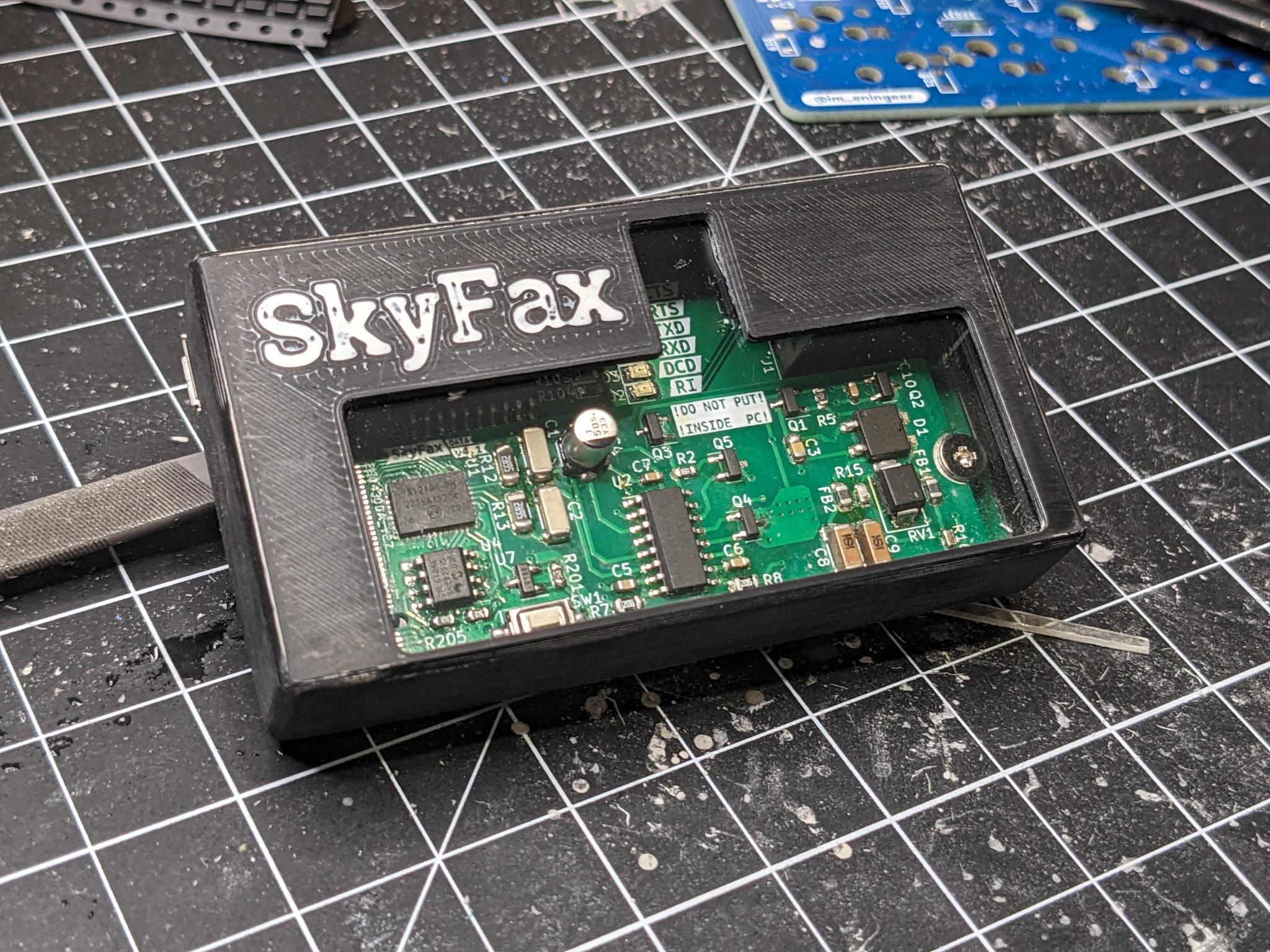
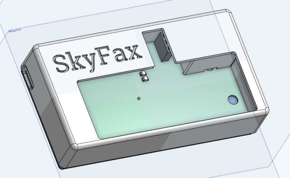
I've also designed and printed a case to go with it. The STL files can be found under /case. Or on OnShape.
Version 3.0:
If you don't have access to a working landline or a proper telephone line simulator two modems can be connected back to back directly.
There are this and this pages, but I have found this circuit to work for me:
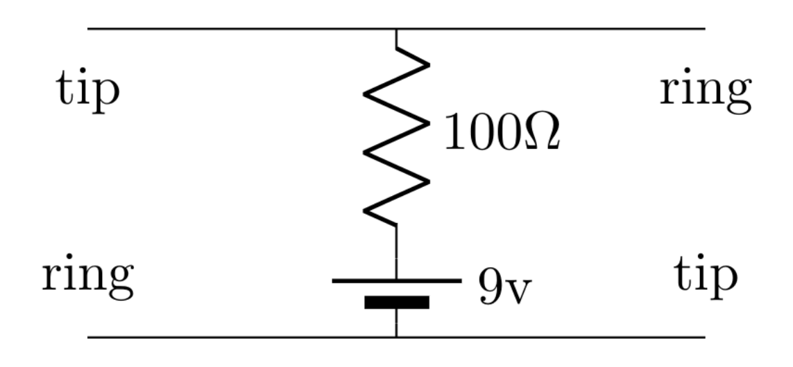
The voltage and resistance can be tweaked to provide ~20mA of current with the modem/phone off-hook.
If you'd like the schematic or just have a PCB made for the line simulator, check out the LineSim project included in this repo.
Once hooked up, you want to disable the dialtone detection with the command ATX3. Then you can just dial with ATDT on one modem and answer with ATA on the other.
See AN93 section 5.4 for details on all the AT commands supported.
| Qty | Value | Footprint | References |
|---|---|---|---|
| 2 | RJ11 | LineSim:RJ11 | J1, J2 |
| 1 | 100 | Resistor_THT:R_Axial_DIN0207_L6.3mm_D2.5mm_P7.62mm_Horizontal | R1 |
| 1 | 470 | Resistor_THT:R_Axial_DIN0207_L6.3mm_D2.5mm_P7.62mm_Horizontal | R2 |
| 1 | 9V | LineSim:BAT_BH9VPC | BT1 |
| 1 | LED | LED_THT:LED_D5.0mm | D1 |
| 1 | SW_SPST | LineSim:SW_GF-123-0054 | SW1 |


MicroCoreLabs/Projects
Ted Fried's MicroCore Labs Projects - FPGA CPU cores and emulators for the 8088, 8086, 8051, 6502, 68000, Z80, Risc-V, and also Typewriter and EPROM Emulator projects.


agranlund/raven
Homemade MC68060 + DSP56303 Atari-compatible computer. Hardware, firmware, and software stack

rjwalters/kicad-tools
Standalone Python tools for parsing and manipulating KiCad schematic and PCB files

Board-Folk/MegaCD-Main-BD
Reproductions of main board PCBs for Sega's Mega CD/Sega CD add-on for the Mega Drive/Genesis console.

shibukawa/bdf
BDF is a browser document-preview suite: it combines converters for many formats (Go/WASM), a browser renderer of about 23 KB gzipped, and a compact intermediate format.

marsairforce/breakout_boards
Small circuit boards to assist with breadboard prototyping with SMD packages.
It measures 29.7 × 29 mm and has 4 copper layers, 1.6 mm thick.
7 parts. The full list of its parts is on this page, with links to each part's symbol and footprint where PCBKit's library has them.
From the ME-IRL/SkyFax repository on GitHub, at the commit this page was made from: the board is LineSim/LineSim.kicad_pcb and its schematic LineSim/LineSim.kicad_sch. PCBKit opens the board in the browser, with nothing to install.
Its repository states no licence, so its author keeps all rights: ask ME-IRL before reusing the design.
