2 layers31.2 × 96.4 mm
Lrima ground
LRIMa-Qc/iot_obj-sicro-sensor
All in one smart IoT greenhouse monitoring and managing system
10 partsCC-BY-4.0

 LRIMa-Qc/iot_obj-sicro-sensor
All in one smart IoT greenhouse monitoring and managing system
Lrima main is an open-source printed circuit board by LRIMa-Qc, from the LRIMa-Qc/iot_obj-sicro-sensor repository on GitHub, published under the CC-BY-4.0 licence. It is a 2-layer board of 33.5 × 78.3 mm with 41 parts on 53 nets, routed with 323 tracks and 48 vias.
It is built around the STCC4-D-R3, ER10BGFBK and TLC555CD, with the TS-1101-C-W, BS-24-A1AJ008 and NCD0603R1 among its other parts. Its parts include 9 capacitors, 7 resistors, 6 ICs, 2 diodes and 1 connector.


Authors : LRIMa (Laboratoire de Recherche Informatique de Maisonneuve)
code/
├── actioneur       (esp32 code)
├── broadcaster     (sensor code [nrf52833])
├── central         (python BLE scanning and ALIVEcode integration)
└── central-nrf     (BLE receiver [nrf52840dongle])
schematic/
├── lrima-main/     (Main board KiCad project)
└── lrima-ground/   (Ground board KiCad project)
models/
└── sensor-casing/ (3D CAD models for enclosure)The schematics and PCB were designed using KiCad EDA software There is a protective layer that needs to be applied on the ground part of the pcb to prevent corrosion
v3.2.4v3.2.4Before building the broadcaster program, you must make sure that you changed the CONFIG_BLE_USER_DEFINED_MAC_ADDR and the CONFIG_BLE_USER_DEFINED_NAME so that they are unique. Note that the CONFIG_BLE_USER_DEFINED_NAME must end with a number (ex : 01). If you need mac address, you can use this mac address generator.
The broadcaster uses the sysbuild system from NCS v3.2.4. To build the program for the nrf52833 using the nRF Connect VS Code extension:
lrima_greenhouse_nrf52833 boardNote: If flashing fails, use the erase and flash option to perform a full erase first.
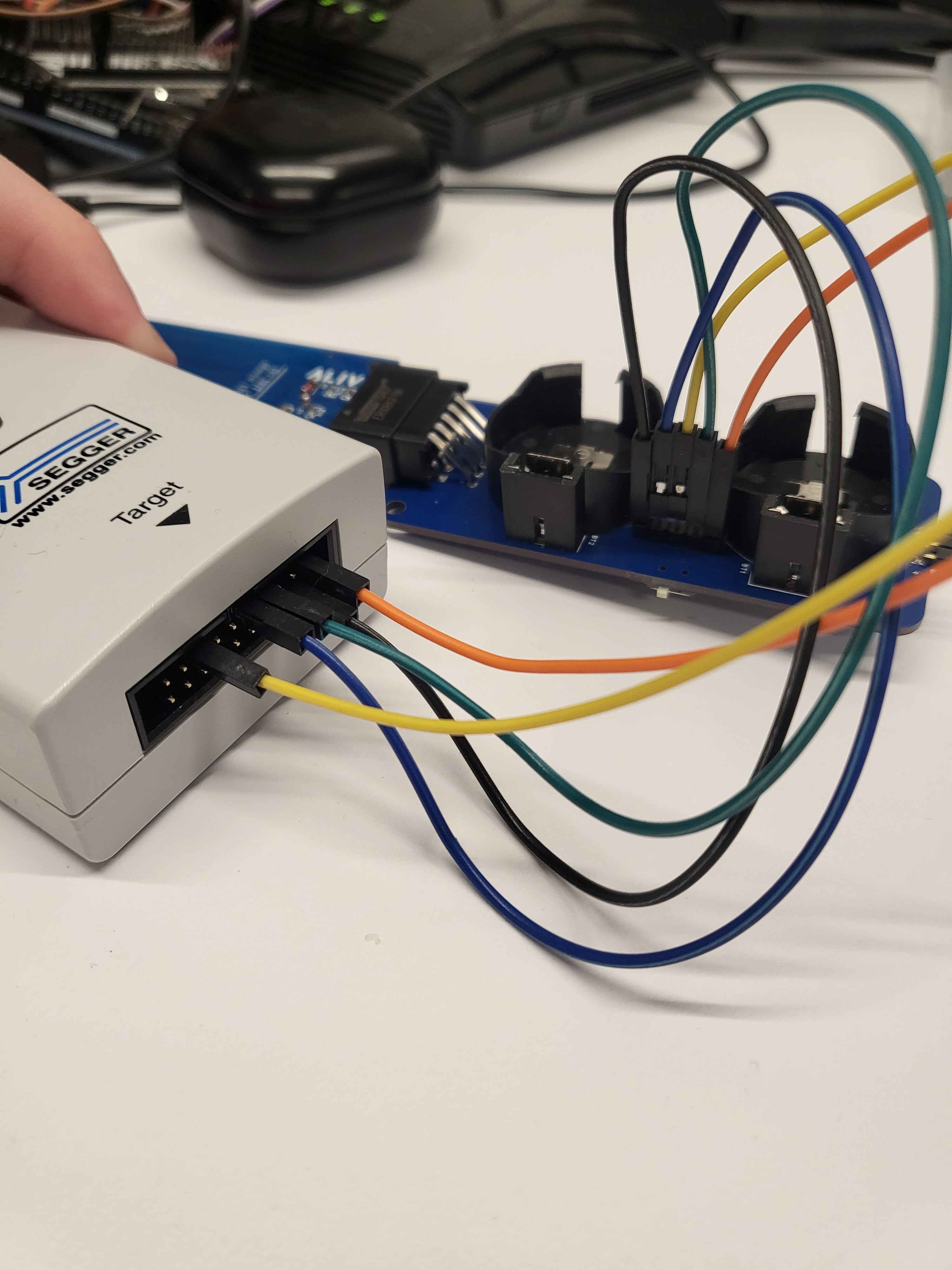
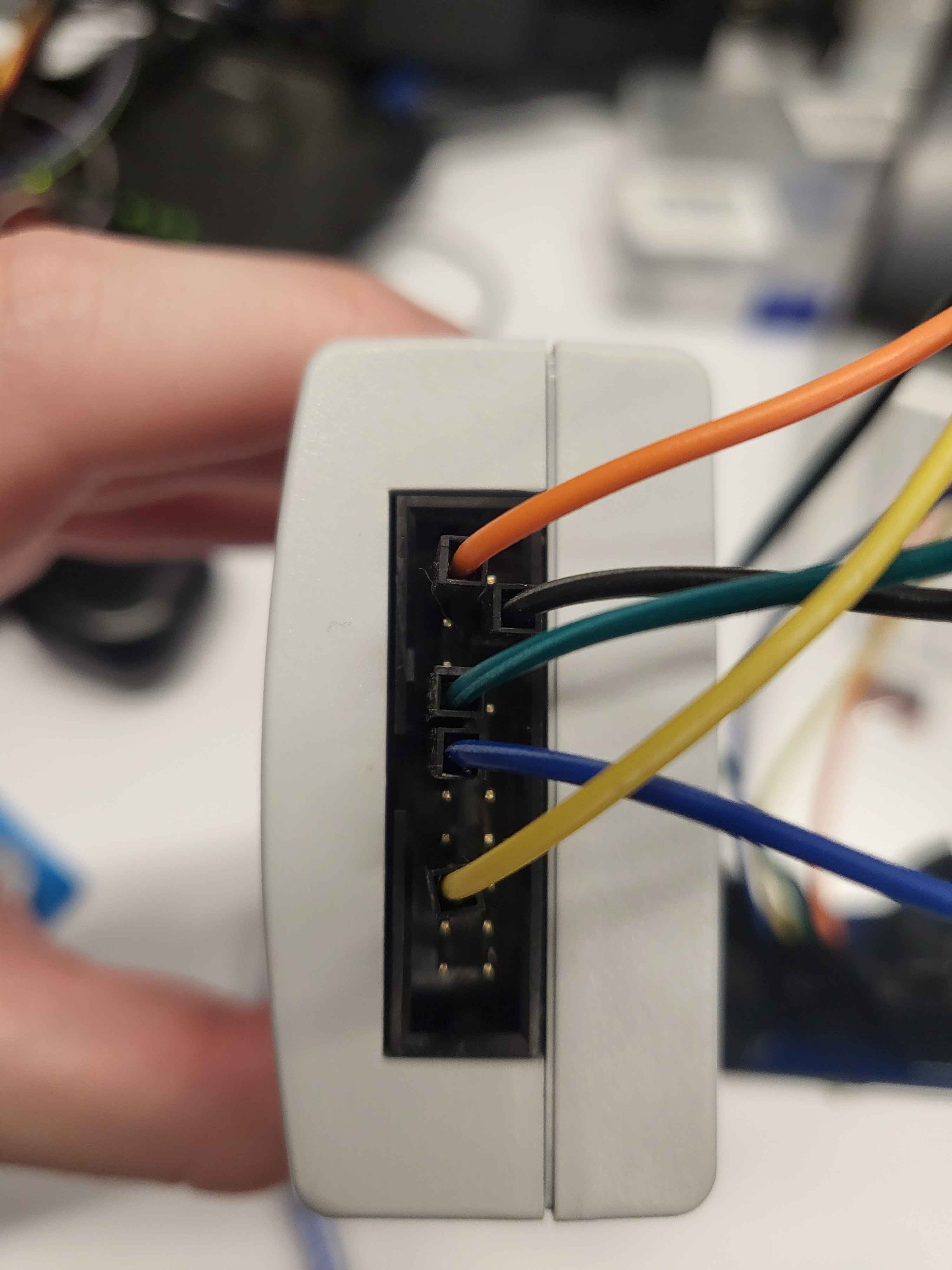
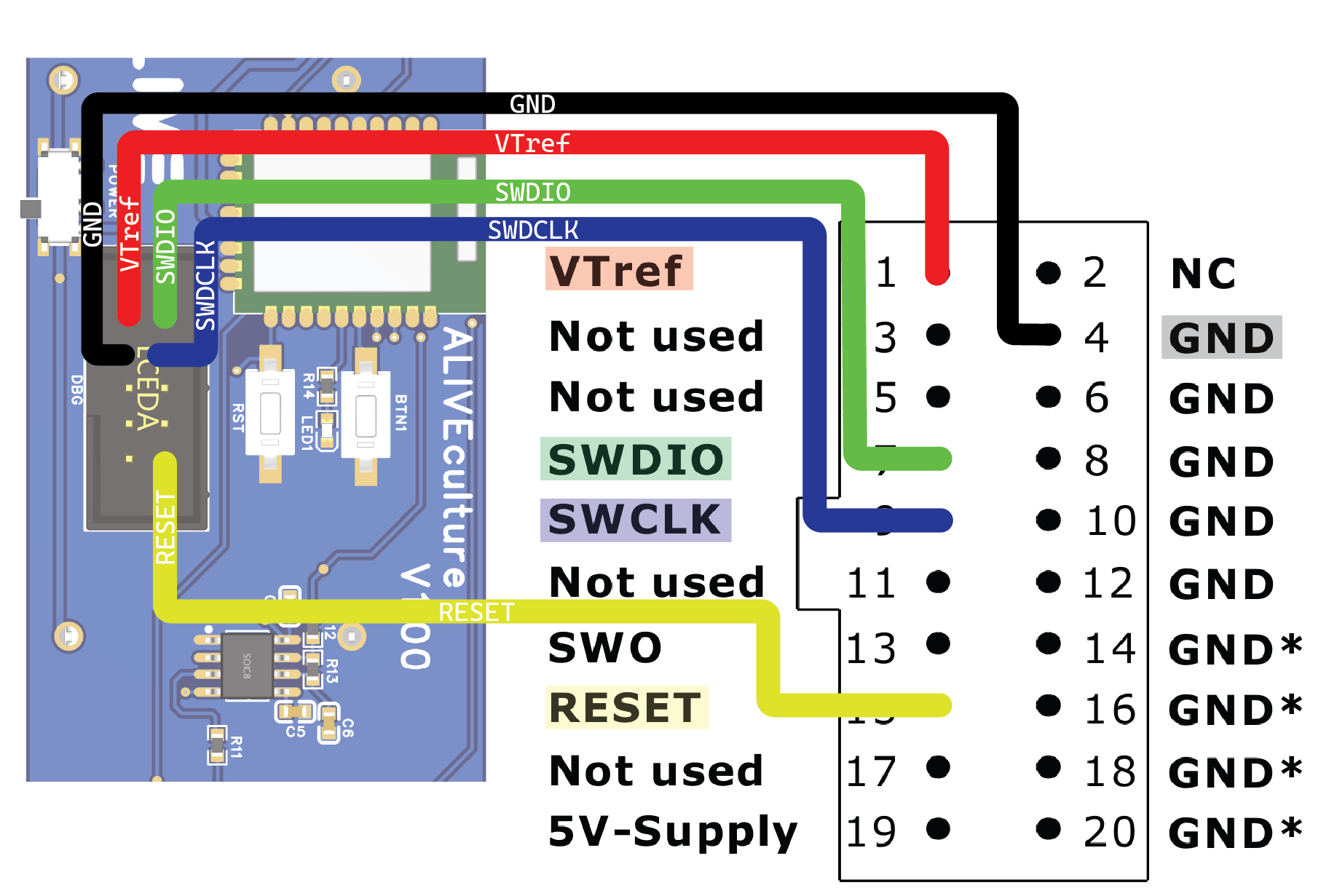
The board supports over-the-air firmware updates. To prepare an update:
build/broadcaster/zephyr/zephyr.signed.binCONFIG_BLE_DFU_ADV_DURATION_SEC) to start the updateCONFIG_BLE_USER_DEFINED_NAME)DFU tab and select zephyr.signed.binUpload and monitor the progress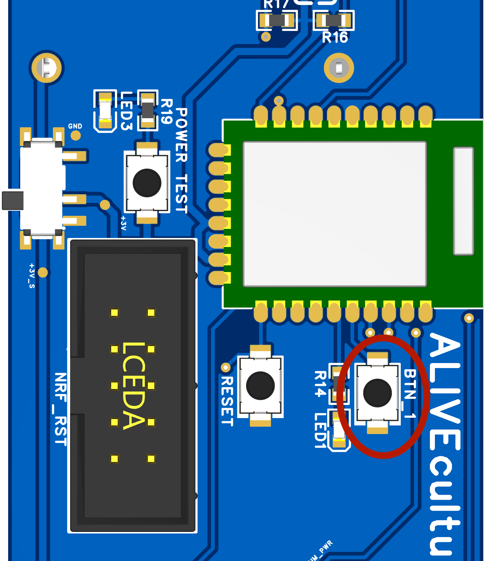
The broadcaster uses a single BLE advertising workflow. It sends sensor data uplink and then opens a short scan window to receive a downlink sleep update when needed. The user can wake up the device at any time by pressing button1. There is never a connection established, and all communication is done through advertisements and scan responses.
The broadcaster collects sensor data and transmits it BLE advertisements:
Supported sensors:
Transmission behavior:
CONFIG_SENSOR_SLEEP_DURATION_SECCONFIG_BLE_ADV_DURATION_SEC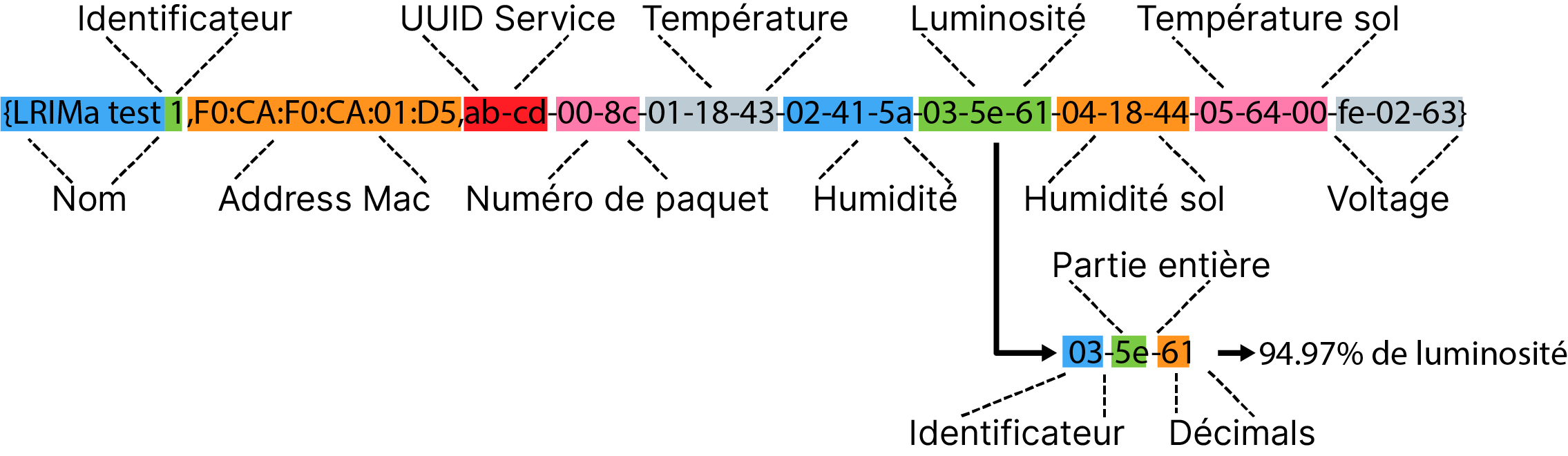
Note: The diagram above predates the latest payload format. See the broadcaster documentation for the full 29-byte layout and presence bitmap details.
The central-nrf firmware runs on the nRF52840 dongle to receive BLE broadcasts from the broadcaster.
Building:
nrf52840dongle_nrf52840 boardbuild/zephyr/zephyr.hex fileThe central application handles BLE scanning, data collection, and integration with ALIVEcode.
Core modules:
core/storage.py - Persistent data managementcore/payload.py - Sensor data parsing and validationcore/aliot_sync.py - ALIVEcode cloud integrationcore/downlink_advertiser.py - BlueZ D-Bus advertiser for sleep-time downlink framescore/health.py - System health monitoringcore/config.py - Configuration managementSetup and running:
Plug the Central-nrf dongle into a computer or Raspberry Pi
Configure the application:
config.ini.example to config.iniobject_id and auth_token from your ALIVEcode.ca IoT projectInstall dependencies:
# For Raspberry Pi 4
pip install -r requirements_pi4.txt

# For Raspberry Pi 5
pip install -r requirements_pi5.txt
(Using a Python virtual environment is recommended)
dbus-next is required because downlink sleep updates are emitted through BlueZ D-Bus advertising APIs.
Run the application:
python main.pyPower on the broadcaster devices
The application will automatically scan for broadcaster devices, collecting sensor data and synchronizing with ALIVEcode.
It publishes each node under /doc/<device_index> including /doc/<device_index>/sleep_duration_sec, and uses /doc/sleep_time as the desired target for downlink sleep updates.
| Qty | Value | Footprint | References |
|---|---|---|---|
| 4 | MountingHole | MountingHole:MountingHole_2.2mm_M2 | H1, H2, H3, H4 |
| 3 | 100n | Capacitor_SMD:C_0603_1608Metric_Pad1.08x0.95mm_HandSolder | C4, C5, C8 |
| 3 | TS-1101-C-W | Button_Switch_SMD:SW-SMD_L6.0-W3.3-LS8.0 | BTN, RST, SW4 |
| 2 | 10k | Resistor_SMD:R_0603_1608Metric_Pad0.98x0.95mm_HandSolder | R6, R7 |
| 2 | 12p | Capacitor_SMD:C_0603_1608Metric_Pad1.08x0.95mm_HandSolder | C10, C11 |
| 2 | 470Ω | Resistor_SMD:R_0603_1608Metric_Pad0.98x0.95mm_HandSolder | R4, R5 |
| 2 | BS-24-A1AJ008 | PCBLIB_BAT-TH_BS-24-A1AJ013_2026-01-08:BAT-TH_BS-24-A1AJ013 | BT1, BT2 |
| 2 | NCD0603R1 | LED_SMD:LED_0603_1608Metric_Pad1.05x0.95mm_HandSolder | LED1, LED2 |
| 2 | ~ | Jumper:SolderJumper-2_P1.3mm_Open_RoundedPad1.0x1.5mm | JP3, JP4 |
| 2 | ~ | Jumper:SolderJumper-2_P1.3mm_Bridged_RoundedPad1.0x1.5mm | JP1, JP2 |
| 1 | 1.6kΩ | Resistor_SMD:R_0603_1608Metric_Pad0.98x0.95mm_HandSolder | R3 |
| 1 | 100nF | Capacitor_SMD:C_0603_1608Metric_Pad1.08x0.95mm_HandSolder | C1 |
| 1 | 10kΩ | Resistor_SMD:R_0603_1608Metric_Pad0.98x0.95mm_HandSolder | R1 |
| 1 | 10nF | Capacitor_SMD:C_0603_1608Metric_Pad1.08x0.95mm_HandSolder | C2 |
| 1 | 10u | Capacitor_SMD:C_0603_1608Metric_Pad1.08x0.95mm_HandSolder | C9 |
| 1 | 10uH | Inductor_SMD:L_0603_1608Metric | L1 |
| 1 | 2.54-1*3P母 | Connector_PinHeader_2.54mm:PinHeader_1x03_P2.54mm_Horizontal | P1 |
| 1 | 32.768kHz | Crystal:Crystal_SMD_3215-2Pin_3.2x1.5mm | Y1 |
| 1 | 330Ω | Resistor_SMD:R_0603_1608Metric_Pad0.98x0.95mm_HandSolder | R2 |
| 1 | 470pF | Capacitor_SMD:C_0603_1608Metric_Pad1.08x0.95mm_HandSolder | C3 |
| 1 | 5-146277-5 | Connector_PinHeader_2.54mm:PinHeader_1x05_P2.54mm_Vertical | U4 |
| 1 | ER10BGFBK | Connector_PCBEdge:CONN-TH_10P-P2.54_WINGTAT_ER10BGFBK | U3 |
| 1 | MSK12C02 | Button_Switch_SMD:SW_SPDT_PCM12 | SW3 |
| 1 | NRF_RST | PCBLIB_SMD-43_L18.0-W13.0-P1.27-E73-2G4M08S1E_2026-01-13:SMD-43_L18.0-W13.0-P1.27-E73-2G4M08S1E | U2 |
| 1 | SHT4x | FootprintsLRIma:SHT4X | U5 |
| 1 | STCC4-D-R3 | Package_LGA:STCC4DR3 | IC1 |
| 1 | TLC555CD | Package_SO:SOIC-8_3.9x4.9mm_P1.27mm | U1 |
LRIMa-Qc/iot_obj-sicro-sensor
All in one smart IoT greenhouse monitoring and managing system

Liesegang/env_sensor
Outdoorの開発・検証はファームウェア、 Web受信アプリ、BLE仕様を参照。 Card firmwareはv2基板で毎分測定・BLE送信、 10分ごとのSD一括記録、1時間ごとの電子ペーパー更新を行う。 iPhoneアプリは共通BLEで受信し、バックグラウンド収集・端末内の履歴保存・JSON / CSV書き出しを行う。 資料の一覧はデータシートにある。


brown-studios/minuet
Minuet upgrades your MAXXAIR Maxxfan with a brushless DC motor, home automation features, and accessories.


Mathesar/14mhz-accelerator
14MHz 68000 accelerator with 1MB fast ram for amiga 500

niwa-yamaguchi/Contact-Monitor-Board
スキャン出力が H になると、その ch の LED 側と MOSFET 側が同時にアクティブになります。 外部接点が閉じていれば電流が流れて LED が点灯し、開いていれば経路が切れて消灯します。 出力が L の間はゲートも L なので MOSFET が OFF になり、その ch は完全に切り離されます。

SolderedElectronics/Capacitive-soil-sensor-hardware-design
Hardware design, BOM, gerbers and 3D files for Capacitive-soil-sensor designed by Soldered Electronics.

dolson14/k7arx
Circuit and PCB Designs, anything else related to radio and electronics
It measures 33.5 × 78.3 mm and has 2 copper layers, 1.6 mm thick.
41 parts, built around the STCC4-D-R3, ER10BGFBK, TLC555CD and TS-1101-C-W. The full list of its parts is on this page, with links to each part's symbol and footprint where PCBKit's library has them.
From the LRIMa-Qc/iot_obj-sicro-sensor repository on GitHub, at the commit this page was made from: the board is schematic/lrima-main/lrima-main.kicad_pcb and its schematic schematic/lrima-ground/lrima-ground.kicad_sch. PCBKit opens the board in the browser, with nothing to install.
Its repository publishes it under the CC-BY-4.0 licence: you may reuse it on that licence's terms (keep the author's notice, and for a copyleft licence share your changes alike).