8 layers75 × 75 mm

 mrbutterfly105/masters_thesis
This is my master’s thesis repo.
Mibico RU is an open-source printed circuit board by mrbutterfly105, from the mrbutterfly105/masters_thesis repository on GitHub. It is a 6-layer board of 75 × 75 mm with 257 parts on 204 nets, routed with 1,962 tracks and 385 vias.
It is built around the TLV9001IDCK, MAX3485ED and TCAN332D, with the BME280, LMT86DCK and MICS-4514 among its other parts. Its parts include 110 resistors, 56 capacitors, 30 ICs, 16 transistors and 8 diodes. It belongs with the STM32 boards of this library.


Název práce: Návrh řídicího modulu pro experiment MIBICO v rámci mise CIMER
Autor: Bc. Tomáš Paulysko
Vedoucí: Ing. Jiří Veverka
Rok odevzdání: 2026
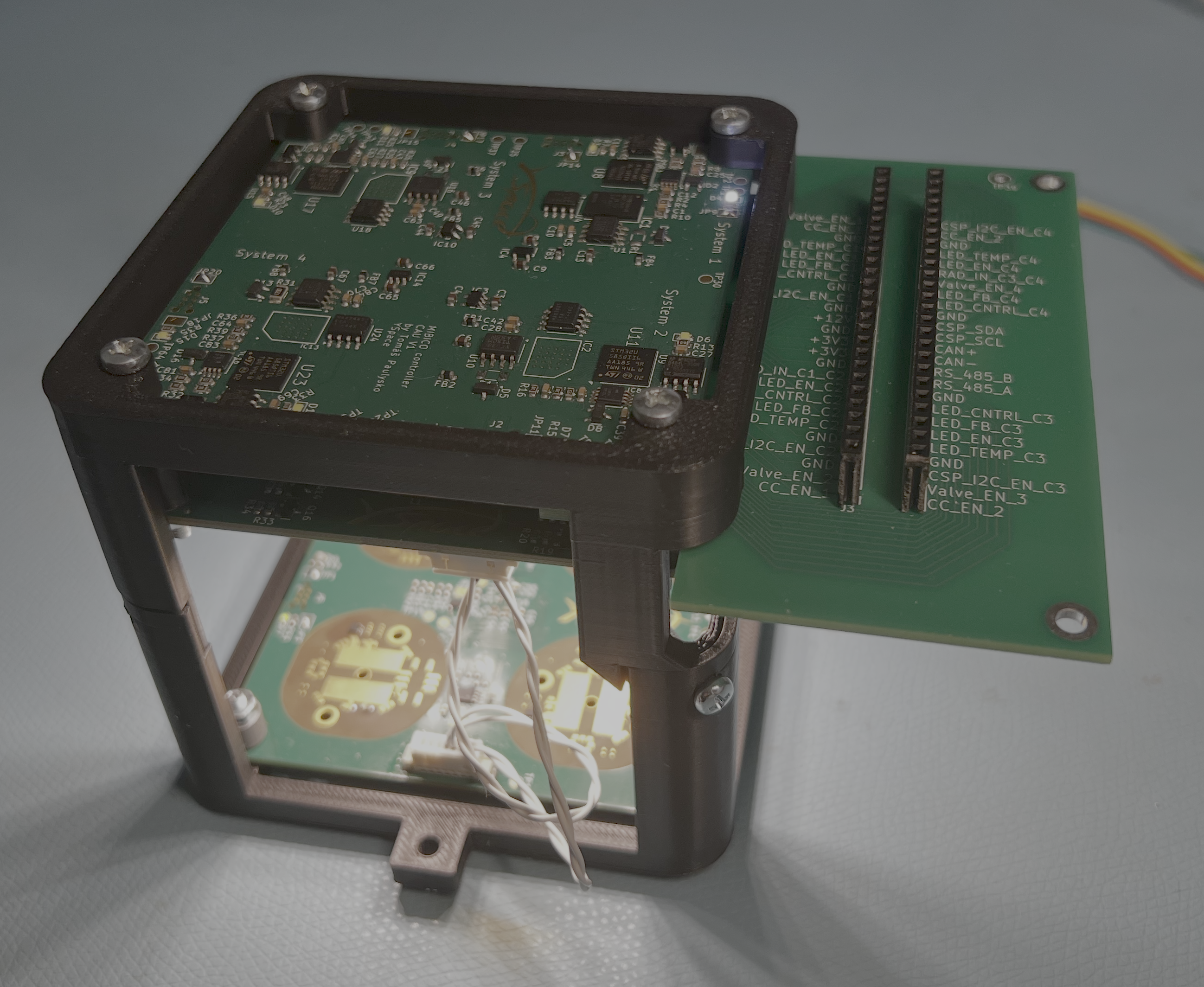
Tento repozitář slouží jako elektronická příloha diplomové práce. Neobsahuje text celé práce, ale podklady k návrhu první hardwarové revize řídicí elektroniky biologického payloadu MIBICO pro studentskou CubeSat misi CIMER. Payload MIBICO je zaměřen na ověření rehydratace vysušených sinic na oběžné dráze Země a na sledování jejich biologické aktivity v podmínkách kosmického prostředí.
Navržený systém zajišťuje autonomní řízení experimentu, aktivaci biologických vzorků, pořizování obrazových dat, měření vybraných veličin v okolí experimentu, řízení osvětlení, temperování a komunikaci s hlavním systémem družice. Řešení respektuje omezení CubeSat platformy, zejména dostupný prostor, energetický rozpočet a požadavky na spolehlivost.
Repozitář je rozdělen do dvou hlavních částí:
HW/ - KiCad projekty navržených desek plošných spojů.FW/ - Firmware projekty pro STM32CubeIDE.fotky/ - Fotografie modulůV adresáři HW/ jsou uloženy projekty jednotlivých elektronických modulů:
mibico_CAU - Camera Unit, hlavní řídicí a kamerový modul.mibico_PU - Power Unit, výkonový modul pro napájení, osvětlení a aktivaci experimentu.mibico_RU - Rehydratation Unit, modul pro měření u vzorku, zpětnou vazbu rehydratace a temperování.mibico_breakout - pomocný vývojový/připojovací modul.Adresář FW/ obsahuje firmware pro moduly CAU_FW a RU_FW. Projekty vycházejí ze STM32CubeIDE a jsou určeny pro mikrokontroléry řady STM32U5. Součástí jsou zdrojové soubory aplikační logiky, konfigurace periferií, HAL/CMSIS knihovny a ladicí výstupy z vývoje.
Hardwarové projekty lze otevřít v KiCadu. Firmware projekty jsou připraveny pro STM32CubeIDE; při práci s nimi je vhodné zkontrolovat konkrétní verzi STM32CubeIDE, konfiguraci toolchainu a cesty generované vývojovým prostředím. Ladicí adresáře Debug/ jsou ponechány jako součást vývojové přílohy a mohou obsahovat build artefakty.
| Qty | Value | Footprint | References |
|---|---|---|---|
| 29 | 100n/50V | Capacitor_SMD:C_0603_1608Metric | C10, C11, C12, C13, C19, C24, C25, C26, C27, C31, C32, C33, C34, C35, C36, C37 +13 |
| 24 | 1K8 | Resistor_SMD:R_0603_1608Metric | R6, R10, R11, R24, R25, R26, R27, R28, R29, R50, R51, R52, R53, R54, R55, R66 +8 |
| 14 | 1K | Resistor_SMD:R_0603_1608Metric | R1, R3, R5, R17, R19, R21, R32, R33, R43, R45, R47, R61, R63, R65 |
| 13 | 100R | Resistor_SMD:R_0603_1608Metric | R12, R13, R30, R31, R35, R56, R57, R72, R73, R109, R110, R111, R112 |
| 12 | 10K | Resistor_SMD:R_0603_1608Metric | R14, R23, R34, R36, R39, R40, R41, R42, R58, R74, R79, R80 |
| 12 | DMN3042L | Package_TO_SOT_SMD:SOT-23 | Q1, Q2, Q5, Q6, Q7, Q8, Q10, Q11, Q13, Q14, Q15, Q16 |
| 10 | 100n/50V | Capacitor_SMD:C_0402_1005Metric | C14, C15, C16, C17, C18, C52, C53, C54, C55, C56 |
| 8 | 0R | Resistor_SMD:R_0603_1608Metric | R15, R49, R60, R75, R82, R83, R86, R87 |
| 8 | 1u/50V | Capacitor_SMD:C_0603_1608Metric | C1, C2, C7, C8, C21, C22, C28, C29 |
| 8 | 82R | Resistor_SMD:R_0603_1608Metric | R93, R94, R95, R96, R101, R102, R103, R104 |
| 8 | DNP | Resistor_SMD:R_0603_1608Metric | R16, R48, R59, R76, R81, R84, R85, R88 |
| 6 | , , , , , | ||
| 4 | 100K | Resistor_SMD:R_0603_1608Metric | R2, R18, R44, R62 |
| 4 | 10u/50V | Capacitor_SMD:C_0603_1608Metric | C47, C48, C49, C50 |
| 4 | 1K5 | Resistor_SMD:R_0603_1608Metric | R4, R20, R46, R64 |
| 4 | 1n/50V | Capacitor_SMD:C_0603_1608Metric | C3, C9, C23, C30 |
| 4 | 22K | Resistor_SMD:R_0603_1608Metric | R97, R98, R99, R100 |
| 4 | 47K | Resistor_SMD:R_0603_1608Metric | R89, R90, R91, R92 |
| 4 | 51R | Resistor_SMD:R_0603_1608Metric | R105, R106, R107, R108 |
| 4 | BAT54J | Diode_SMD:D_SOD-323F | D13, D14, D15, D16 |
| 4 | BME280 | Package_LGA:Bosch_LGA-8_2.5x2.5mm_P0.65mm_ClockwisePinNumbering | U3, U10, U12, U15 |
| 4 | GND | TestPoint:TestPoint_Pad_D1.5mm | TP11, TP12, TP13, TP14 |
| 4 | IN-S63DTLS | LED_SMD:LED_0603_1608Metric | Q3, Q4, Q9, Q12 |
| 4 | LMT86DCK | Package_TO_SOT_SMD:SOT-353_SC-70-5 | U2, U7, U11, U14 |
| 4 | MICS-4514 | MiCS-4514:MICS_10-SMD | U16, U17, U18, U19 |
| 4 | SHT4x | Sensor_Humidity:Sensirion_DFN-4_1.5x1.5mm_P0.8mm_SHT4x_NoCentralPad | U20, U21, U22, U23 |
| 4 | STCC4-D-R3 | STCC4:STCC4DR3 | IC3, IC4, IC5, IC6 |
| 4 | TLV9001IDCK | Package_TO_SOT_SMD:SOT-353_SC-70-5 | U1, U4, U9, U13 |
| 4 | measure_pads | sponge_pad:Sponge_pads | J12, J13, J14, J15 |
| 2 | +12V | TestPoint:TestPoint_Pad_D1.5mm | TP9, TP10 |
| 2 | +3V3 | TestPoint:TestPoint_Pad_D1.5mm | TP1, TP2 |
| 2 | +5V | TestPoint:TestPoint_Pad_D1.5mm | TP7, TP8 |
| 2 | 4K7 | Resistor_SMD:R_0603_1608Metric | R77, R78 |
| 2 | LED | LED_SMD:LED_0603_1608Metric | D6, D7 |
| 2 | LOGO | LOGO | G***, G*** |
| 2 | NUP2105L | Package_TO_SOT_SMD:SOT-23 | D4, D12 |
| 1 | 120R | Resistor_SMD:R_1206_3216Metric | R22 |
| 1 | 4u7 | Capacitor_SMD:C_0603_1608Metric | C20 |
| 1 | 53398-0671 | Connector_Molex:Molex_PicoBlade_53398-0671_1x06-1MP_P1.25mm_Vertical | J7 |
| 1 | 53398-0771 | Connector_Molex:Molex_PicoBlade_53398-0771_1x07-1MP_P1.25mm_Vertical | J6 |
| 1 | Conn_ARM_SWD_TagConnect_TC2030-NL | Connector:Tag-Connect_TC2030-IDC-NL_2x03_P1.27mm_Vertical | J5 |
| 1 | MAX3485 | Package_SO:SOIC-8_3.9x4.9mm_P1.27mm | U6 |
| 1 | PH3_BOOT0 | TestPoint:TestPoint_Pad_D1.5mm | TP21 |
| 1 | PH3_GND | TestPoint:TestPoint_Pad_D1.5mm | TP19 |
| 1 | PH3_RST | TestPoint:TestPoint_Pad_D1.5mm | TP20 |
| 1 | SPX3819M5-L-5-0 | Package_TO_SOT_SMD:SOT-23-5 | U24 |
| 1 | STM32U575QIIx | Package_BGA:UFBGA-132_7x7mm_Layout12x12_P0.5mm | U25 |
| 1 | STM6822TWY6F | SOT95P280X145-5N:SOT95P280X145-5N | IC1 |
| 1 | SolderJumper_2_Open | Jumper:SolderJumper-2_P1.3mm_Open_Pad1.0x1.5mm | JP1 |
| 1 | TCA4307DGKR | Package_SO:Texas_S-PDSO-G8_3x3mm_P0.65mm | IC2 |
| 1 | TCAN332 | Package_SO:JEITA_SOIC-8_3.9x4.9mm_P1.27mm | U5 |
| 1 | WDG_EN | Jumper:SolderJumper-2_P1.3mm_Open_TrianglePad1.0x1.5mm | JP2 |
| 1 | pwr_led_EN | Jumper:SolderJumper-2_P1.3mm_Open_TrianglePad1.0x1.5mm | JP3 |
The 251 most common of 257 parts.


embeddedos-org/eCAD-Hardware-Products
Hardware designs + EE docs + Board datasheets of Multiple products


Liesegang/env_sensor
Outdoorの開発・検証はファームウェア、 Web受信アプリ、BLE仕様を参照。 Card firmwareはv2基板で毎分測定・BLE送信、 10分ごとのSD一括記録、1時間ごとの電子ペーパー更新を行う。 iPhoneアプリは共通BLEで受信し、バックグラウンド収集・端末内の履歴保存・JSON / CSV書き出しを行う。 資料の一覧はデータシートにある。

LRIMa-Qc/iot_obj-sicro-sensor
All in one smart IoT greenhouse monitoring and managing system

brown-studios/minuet
Minuet upgrades your MAXXAIR Maxxfan with a brushless DC motor, home automation features, and accessories.

r-map/rmap
rete monitoraggio ambientale partecipativo documentation at https://doc.rmap.cc


It measures 75 × 75 mm and has 6 copper layers, 1.6 mm thick.
257 parts, built around the TLV9001IDCK, MAX3485ED, TCAN332D and BME280. The full list of its parts is on this page, with links to each part's symbol and footprint where PCBKit's library has them.
From the mrbutterfly105/masters_thesis repository on GitHub, at the commit this page was made from: the board is HW/mibico_RU/mibico_RU.kicad_pcb and its schematic HW/mibico_CAU/CAN_transciver.kicad_sch. PCBKit opens the board in the browser, with nothing to install.
Its repository states no licence, so its author keeps all rights: ask mrbutterfly105 before reusing the design.